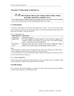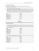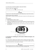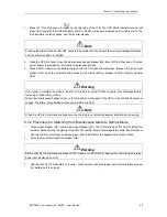
Chapter 6 Operating Instructions
40
MUST400_User manual_EN_REV02 User Manual
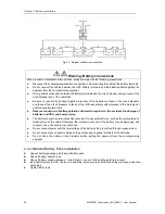
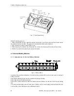
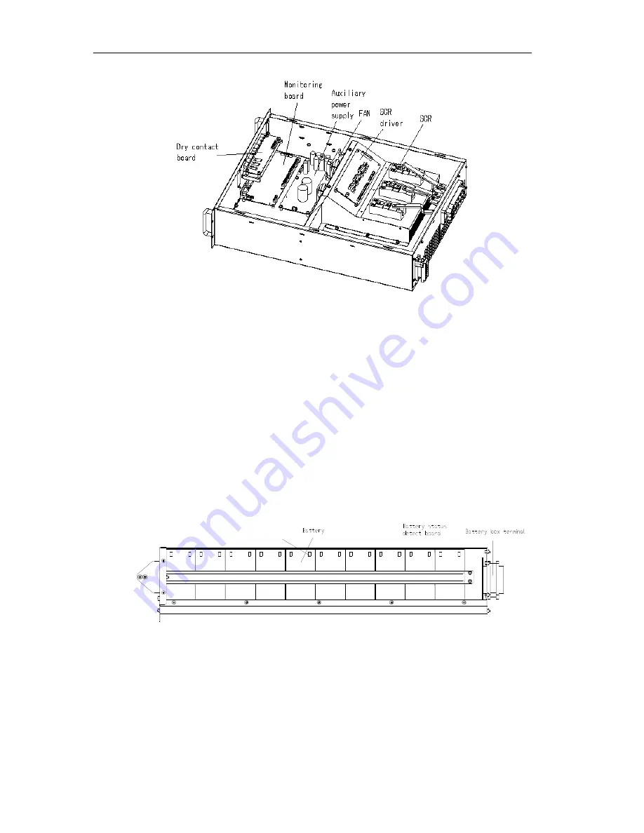
Fig.4- 11: Static Bypass Module
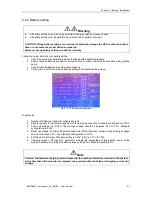
Notes for installing modules:
1. When installing the modules, install the modules from bottom to top. When removing the modules, remove
the modules from top to bottom. The purpose is to maintain the stable center of gravity.
2. After inserting the module, tighten all the screws.
3. When removing the modules, turn off modules first, remove the screws and then remove the modules.
4. Wait for 5 minutes before inserting the removed modules.
4.1 Internal Battery Module
4.1.1 Appearance of Internal Battery Module
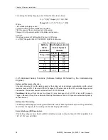
Fig.4- 12: Battery Module
According to the selected configuration, the built-in battery modular UPS can house from none to 4 strings of
battery in parallel.
Each Modular Battery Cabinet can house additional 8 strings of battery.
Each string is made of 4 battery modules.
Each battery module contains ten 9AH/12V batteries and each battery tray has one 50A DC current limiting
fuse.
The maximum discharging current of each layer of battery is 45A. Over charging current will break the fuse
and the LED on front of battery module will display the fault.

