Chapter 3 Installation of UPS Rack System and System
32
MUST400_User manual_EN_REV02 User Manual
3.2.6 Parallel Signal Board
Installation of parallel signal board
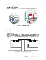
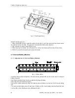
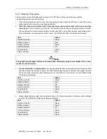
The parallel signal board BJ is installed at the rear of the static switch power module. Refer to fig.3-2,
(a) (b)
Fig.3- 2: Installation of Parallel Signal Board BJ
Remove cable W102 as fig.3-2(a)
Install parallel signal board BJ as fig.3-2(b)
Connect cable 1 and cable 2 as fig.3-2(b)
3.2.7 Control Cables
Parallel control cable
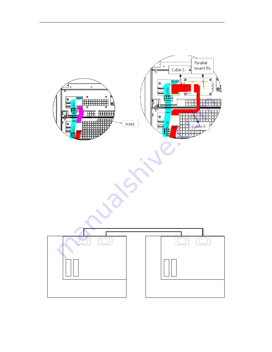
The parallel control cables are designed to be shielded and double insulated, and are connected between the
UPS systems to form a loop as shown below. The parallel signal board BJ is installed at the rear of the static
bypass module. In this case the loop connection ensures the reliability of the parallel system control. Refer to
fig. 3-3
Parallel Signal Board BJ
P1
P2
J1
J2
Rack Modular system UPS1
Parallel Signal Board BJ
P1
P2
J1
J2
Rack Modular system UPS2
Fig.3- 3
: Connection of Parallel Control Cables of “1+N” System

