


-6-
Model G0817 (Mfd. Since 05/16)
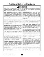
Table Tilt
S
T
U
V
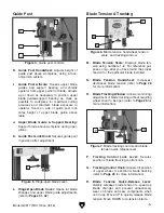
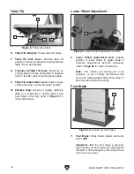
Figure 8. Table tilt controls.
S. Table Tilt Indicator: Shows table tilt angle.
T. Table Tilt Lock Lever: Secures table tilt
position on trunnion. Must be loosened before
table tilt can be adjusted.
U. Trunnion w/Table Tilt Scale: Functions as
a tilting base for table. Graduated in degrees
from 5° left–45° right for setting bevel angle.
V. Table Tilt Adjustment Lever: Adjusts angle
of table tilt using a rack-and-pinion system.
W. Positive Stop: Allows for quickly returning
table to a calibrated 0° setting after it has
been tilted to the right (refer to
Page 47 for
more information).
W
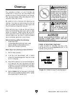
Lower Wheel Adjustment
X
Figure 9. Lower wheel adjustment controls.
X. Lower Wheel Adjustment Hub: Adjusts
position of lower wheel to upper wheel if
coplanar adjustments become necessary
(refer to
Page 68 for more information).
Note: The wheels are factory-set to be
coplanar, so we strongly recommend that
you avoid making adjustments here unless it
becomes absolutely necessary.
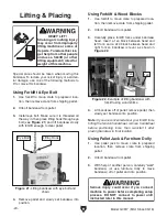
Y. Foot Brake: Stops blade wheels and turns
motor
OFF.
Important: After the foot brake is pressed,
the machine can be restarted by pressing the
ON button. The Emergency Stop button does
not have to be reset.
Foot Brake
Y
Figure 10. Location of foot brake.
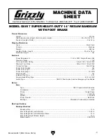
Summary of Contents for G0817
Page 88: ......