


Model G0817 (Mfd. Since 05/16)
-35-
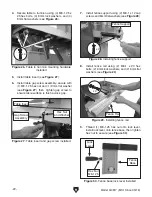
Roller-Disc
Blade
Gullets
Approximately
0.016"
Figure 56. Roller-disc positioned just behind
blade gullets.
Note: With wider blades, it may not be pos-
sible to bring the roller-discs just behind the
blade gullets. Position them as far forward as
possible without allowing the roller-disc hous-
ing to touch the back of the blade.
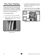
Blade teeth are angled out slightly, pro-
truding wider than the blade thickness;
this is known as blade "tooth set" (see
Figure 57). If angled out parts of the teeth
contact roller-discs during operation, they
will get bent inward, ruining the tooth set.
Therefore, the support bearing must be
set to prevent teeth from contacting roller-
discs during operation (refer to Page 31 for
details).
“Tooth Set”
Wider Than
Blade Thickness
BladeThickness
Figure 57. Illustration of blade "tooth set."
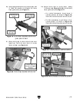
Figure 55. Location of guide block adjustment
cap screw (guide post cover removed for clarity).
Cap Screw
To adjust "Euro-style" roller-discs:
1. DISCONNECT MACHINE FROM POWER!
2. Loosen guide block adjustment cap screw
shown in
Figure 55, then position roller-discs
just behind blade gullets, as illustrated in
Figure 56. Retighten cap screw to secure
setting.
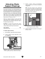
Note: The roller-discs should be positioned
behind the gullets at a distance equal to that
of the support bearing behind the blade (see
Figure 45 on Page 31).
Summary of Contents for G0817
Page 88: ......