


Model G0817 (Mfd. Since 05/16)
-63-
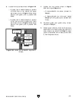
5. Rotate blade tension quick-release lever
counterclockwise to down position to apply
tension to blade.
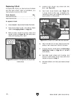
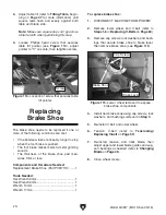
6. Tighten tension adjustment screw (see
Figure 98) until it contacts wheel block plate,
then back it off 1-2 turns.
7. Retighten jam nut.
Adjusting Guide
Post Parallelism
The guide post assembly should remain parallel
with the blade front to back and side to side along
its length of travel. If it does not, follow these
instructions to adjust it.
Important: Make sure the table is aligned with the
blade from side to side and front to back before
beginning these procedures (refer to
Aligning
Table on Page 36 for detailed instructions).
Tools Needed:
Machinist's Square ............................................ 1
Small Ruler ........................................................ 1
Hex Wrench 4mm .............................................. 1
Hex Wrench 5mm .............................................. 1
Hex Wrench 8mm .............................................. 1
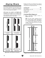
Checking/Adjusting Guide Post
Parallel with Blade Side to Side
1. DISCONNECT MACHINE FROM POWER!
2. Loosen guide post lock knob, lower guide
post to within 1" of table top, then tighten
knob.
Guide Post
(Front View)
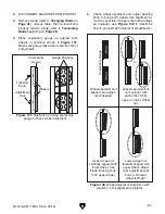
Figure 99. Example of checking guide post
squareness.
3. Place machinist's square on table next to
right-hand side of guide post, as shown in
Figure 99.
— If there is no gap between square and
guide post along its full length, no adjust-
ments need to be made. Proceed to next
procedure.
— If there is a gap between square and the
guide post, guide post is not parallel to
blade. Go to
Step 4.
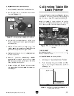
4. Loosen each of the four cap screws shown in
Figure 100
1
⁄
4
-turn
.
Figure 100. Guide post adjustment screws.
5. Gently tap lower part of guide post in appro-
priate direction until there is no gap between
square and guide post.
6. Tighten cap screws shown in Figure 100.
Summary of Contents for G0817
Page 88: ......