


-66-
G0605X/G0606X Extreme Series 12" Table Saw
���
���
���
���
���
���
���
���
���
���
���
���
���
���
���
���
���
���
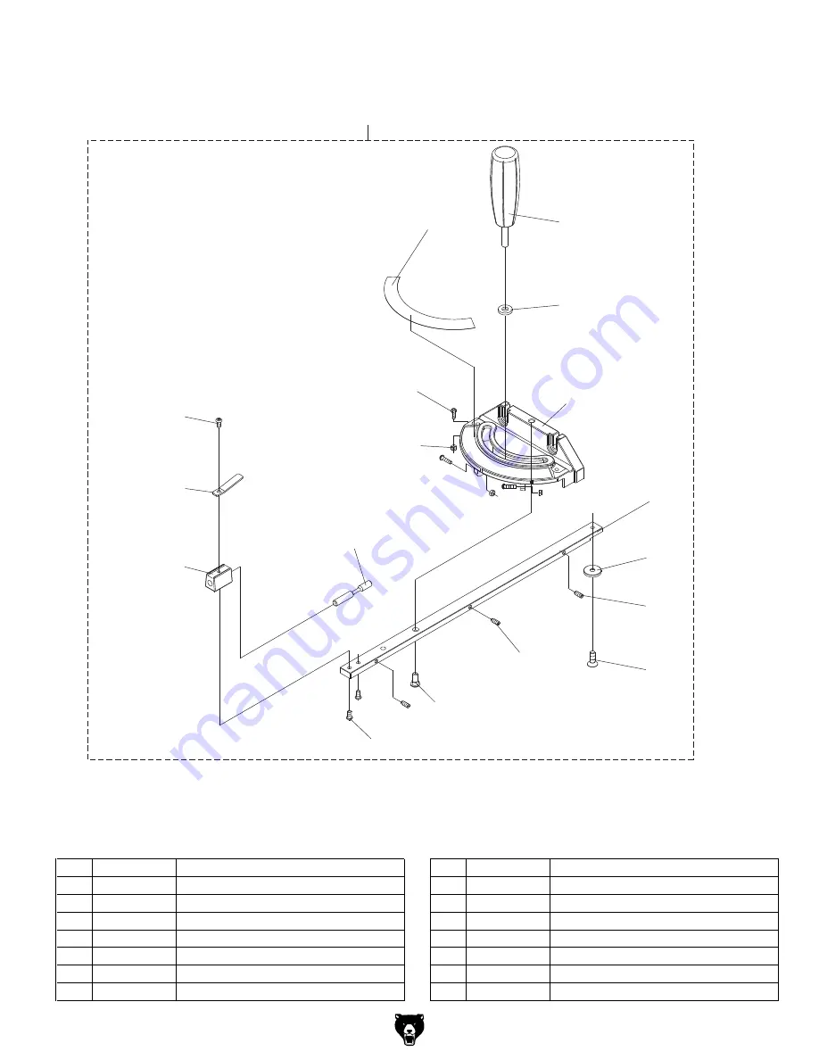
Miter Gauge Assembly Breakdown
REF PART #
DESCRIPTION
REF PART #
DESCRIPTION
400
P0605X400
MITER GAUGE
408
PS04
PHLP HD SCR 1/4-20 X 1/2
401
PS06
PHLP HD SCR 10-24 X 3/8
409
PSS53M
SET SCREW M5-.8 X 12
402
P0605X402
POINTER
410
P0605X410
MITER GAUGE HANDLE
403
P0605X403
BLOCK
411
PW01M
FLAT WASHER 8MM
404
P0605X404
SHAFT
412
P0605X412
MITER GAUGE
405
P0605X405
MITER GAUGE SCALE
413
P0605X413
PLATE
406
P0605X406
PHLP HD SCR 5/32-32 X 5/8
414
P0605X414
GUIDE PLATE
407
P0605X407
HEX NUT 5/32-32
415
PFH9M
FLAT HD SCR M6-1 X 6
Miter Gauge Parts List
Summary of Contents for EXTREME G0605X
Page 2: ... ...
Page 19: ...G0605X G0606X Extreme Series 12 Table Saw 17 Hardware Recognition Chart ...
Page 59: ...G0605X G0606X Extreme Series 12 Table Saw 57 G0605X Wiring Diagram ...
Page 61: ...G0605X G0606X Extreme Series 12 Table Saw 59 G0606X Wiring Diagram 220V 440V WIRING ...
Page 62: ... 60 G0605X G0606X Extreme Series 12 Table Saw G0606X Wiring Diagram 440V ...
Page 63: ...G0605X G0606X Extreme Series 12 Table Saw 61 Cabinet Motor Main Table Breakdown ...
Page 73: ... ...
Page 74: ... ...
Page 75: ......
Page 76: ... ...


