❏
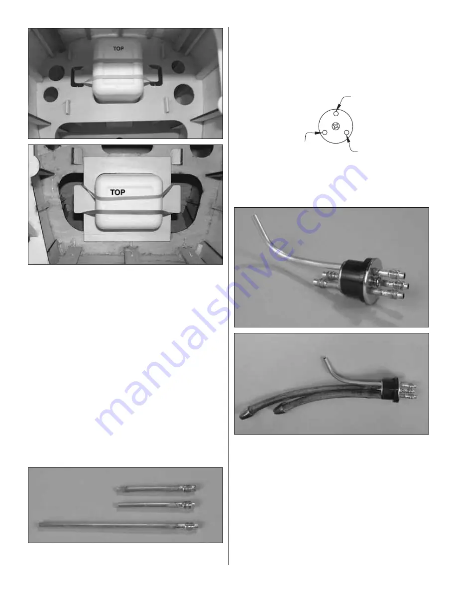
2. Note that there is an upper and a lower mounting
location for the fuel tank. Determine the mounting location for
the engine you will be using. The upper location will be used
for glow engines and most other engines. However, if using a
Fuji 50 engine or another type of engine that interferes with
the front of the fuel tank, mount the tank in the lower location
using the separate plywood fuel tank former. The lower fuel
tank location is also recommended if using the O.S. MAX
FT300 Twin due to the low placement of the carburetor. Notice
that, if using the lower location, the fuel tank will lie flat.
❏
3. Determine the type of fuel tank setup you will be using
and how many metal fuel tubes will be used in the stopper. The
suggested method is to use a three-line system—one line for
filling/emptying the tank, one line for the vent (or pressure if
using a glow engine) and one line for fuel pickup. This setup is
great for modelers who prefer not to use a fueling valve. It also
allows defueling with the model upright (as opposed to
defueling through the vent, which would require that the model
be turned upside-down to pump out all the fuel). If using a
fueling valve, a two-line system will be used.
❏
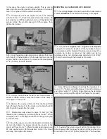
4. If using fuel line barbs (as recommended for gas
engines), replace the aluminum fuel tubes with 1/8" [3.2mm]
brass tubing (not included). Cut the brass tubes to the
correct length, then solder the barbs onto one end of the
tubes. The long brass tube will be bent upward for the vent
inside the tank.
❏
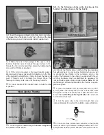
5. Assemble the rubber stopper with the metal plates,
screw and metal fuel tubes as shown in the sketch. (Refer to
this sketch when connecting the fuel lines later on.)
❏
6. Bend the vent tube upward. Solder on the remaining two
fuel line barbs—if used. Connect the pickup and fueling/de
fueling lines to the respective tubes on the back of the
stopper. Be certain to use the correct type of fuel tubing for the
type of engine (gas or glow) you are using. (Remember, Du-
Bro medium neoprene tubing is recommended for gas
engines because it fits tightly. Most types of gas-compatible
tubing expand when immersed in gas, so if the tubing does
not initially fit very tightly, it may loosen its hold and possibly
become disconnected from the clunk or the tubes in the
stopper). Connect a fuel line weight (“clunk”) to both lines. Be
certain the clunk on the end of the pickup line will not contact
the rear of the tank. Make the fueling/defueling line shorter
than the pickup line so they do not become entangled.
RIGHT SIDE
OF PLANE
FRONT VIEW
VENT
FUELING/
DEFUELING
PICKUP
LEFT SIDE
OF PLANE
30


