❏
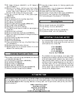
8. IMPORTANT! The same as was done with the servo
mounting screws, remove the screws holding the control
horn to the aileron and add a few drops of thin CA to harden
the “threads” in the aileron. Allow the CA to fully harden,
then remount the horn.
❏
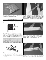
9. Center the aileron and servo arm. Cut the pushrod to
the correct length, then solder it to a large, non-threaded
metal clevis using the techniques described in the following
Expert Tip.
How to Solder
❏
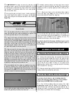
1. Use denatured alcohol or other solvent to thoroughly
clean the pushrod. Use coarse sandpaper to roughen the
end of the pushrod where it is to be soldered.
❏
2. Apply a few drops of soldering flux to the end of the
pushrod, then use a soldering iron or a torch to heat it. “Tin”
the heated area with silver solder (GPMR8070) by applying
the solder to the end. The heat of the pushrod should melt
the solder—not the flame of the torch or soldering iron—
thus allowing the solder to flow. The end of the wire should
be coated with solder all the way around.
❏
3. Place the clevis on the end of the pushrod. Add another
drop of flux, then simultaneously heat the clevis and pushrod.
Slide the clevis the rest of the way onto the pushrod as the
solder melts. Apply another small amount of solder while the
pushrod and clevis are still hot. The same as before, the heat
of the parts being soldered should melt the solder, thus
allowing it to flow. Allow the joint to cool naturally without
disturbing. Avoid excess blobs, but make certain the joint is
thoroughly soldered. The solder should be shiny, not rough. If
necessary, reheat the joint and allow to cool.
❏
4. Immediately after the solder has solidified, but while it
is still hot, carefully use a cloth to quickly wipe off the flux
before it hardens. Important: After the joint cools, coat with
oil to prevent rust. Note: Do not use the acid flux that comes
with silver solder for electrical soldering.
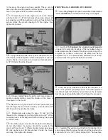
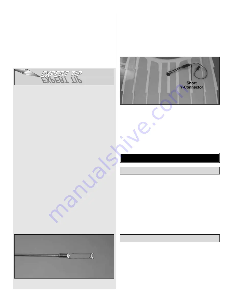
This is what a properly soldered clevis looks like; shiny
solder with good flow, no blobs, flux removed.
❏
10. Slide a silicone retainer over the clevis, then connect
the aileron to the servo with the pushrod. The clevis will be
adjusted and the nut will be tightened when setting up the
radio later.
❏
11. Mount and hook up the remaining three aileron
servos the same way. Note: The servo arms on all four
servos should “point” toward the wing tips.
❏
12. Connect the aileron servo wires in the wings to a
short Y-connector such as the Futaba AEC-13 J-series dual
extension cord (FUTM4130 for Futaba). Secure the
connection with tape or heat shrink tubing.
Hey, that’s about it for the wings. Set the wings in a safe
place (but not too far away!) and get ready to start on
the fuselage.
❏
1. Remove the masking tape and separate the elevators
from the stab and the rudder from the fin. The same as was
done with the ailerons, use a pin to poke several holes in the
covering on the bottom of the stab and elevators and in one
side of the fin and rudder to allow air to escape while
tightening the covering. Use a covering iron with a covering
sock to tighten the covering.
❏
2. Prepare all the hinge slots by test fitting the hinges and
cutting a strip of covering from each slot.
If you haven’t yet done so, get a building stand to
support the fuselage while working on it. The Robart
Super Stand II (ROBP1402) is recommended.
❏
1. Peel off the masking tape and remove the balsa
landing gear cover from the bottom of the fuselage. The
same as was done with the wings and tail surfaces, use a
covering iron with a covering sock to tighten the covering
and remove any wrinkles from the fuselage.
Join the Stab and Fin to the Fuselage
Prepare the Tail Surfaces for Hinging
ASSEMBLE THE FUSELAGE
14


