208
Zodiak Installation and Service Manual
Section 5 — Troubleshooting and Diagnostics
Video Processor Frame Troubleshooting
This section focuses primarily on problems with power to the Video Pro-
cessor frame, vide path troubleshooting, and communication with other
devices.
Basic Frame Functionality Checks
1.
Open the front door of the Video Processor frame and check all frame
modules for any illuminated red fault LEDs. If a red fault LED is
illuminated, reset the Video Processor frame by pressing the
Reset
button on the Control Processor/DSK/Still Store module in the top slot
of the frame and note if any fault lights return.
If any of the fault LEDs remain lit, refer to
for information on
the indicator meaning.
2.
If the frame is not communicating with the Menu panel, source names
will not appear in the Eng Setup – Sources menu. If there is no
communication between the frame and the Main panel, selecting
crosspoints will not change video. To verify that the frame is
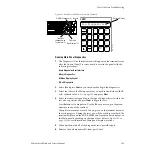
communicating over the Menu and Panel LAN check for blinking
green TX and RX MENU and PANEL LEDs on the Control Proc/Still
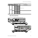
Store/DSK module (
For a more detailed communication troubleshooting procedure, refer to
No Communication Between Main Panel and Frame or System Lockup on
page 166
.
3.
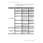
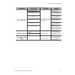
Check the frame module status indicators listed in
to make
sure each module in the frame has correct power and other status.
Modules are listed as they reside in the frame from top to bottom;
indicators are listed as they appear on the front of each module from
left to right.
4.
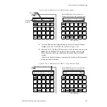
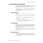
Verify that there is at least one power supply for the 2.5-M/E and two
power supplies for the 3-M/E functioning in the Video Processor frame
at all times, each with the following indicators found at the lower front
of the frame (
•
V AC green LED on (AC line voltage is present).
•
V DC green LED on (DC output to Video Processor frame is
present).
Note
Earlier version power supplies have only one LED which indicates AC power
status.


