150
Zodiak Installation and Service Manual
Section 4 — Maintenance
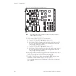
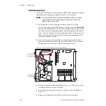
Figure 101. Dual Mix Effects Module Component Layout
Note
For 2.5-M/E systems there will be four extra heat sinks as there is no M/E 3
module. Keep these for spares.
5.
On the module from Slot 3 (3-M/E systems only):
a.
Locate ICs U13 and U46 highlighted in
b.
Install one of the four larger sized heat sinks on the top of each of
these ICs by removing the protective backing from the heat sink
and pressing it firmly onto the IC.
c.
Locate ICs U55 and U67 highlighted in
d.
Install one of the four smaller sized heat sinks on the top of each of
these ICs by removing the protective backing from the heat sink
and pressing it firmly onto the IC.
6.
Plug each module back into its original location in the Video Processor
frame. This can be done while the frame is powered up.
7.
Reset the Video Processor frame by pushing the
RESET
button on the
front of the Control module (
This completes the necessary modifications. You may now install the
new software.
U12
(-00)
U45
(-00)
U13
U46
U54
(-00)
U66
(-00)
U67
U55
069300_01_6347

