background image

8

Installation

Mounting a microphone

Mounting a microphone

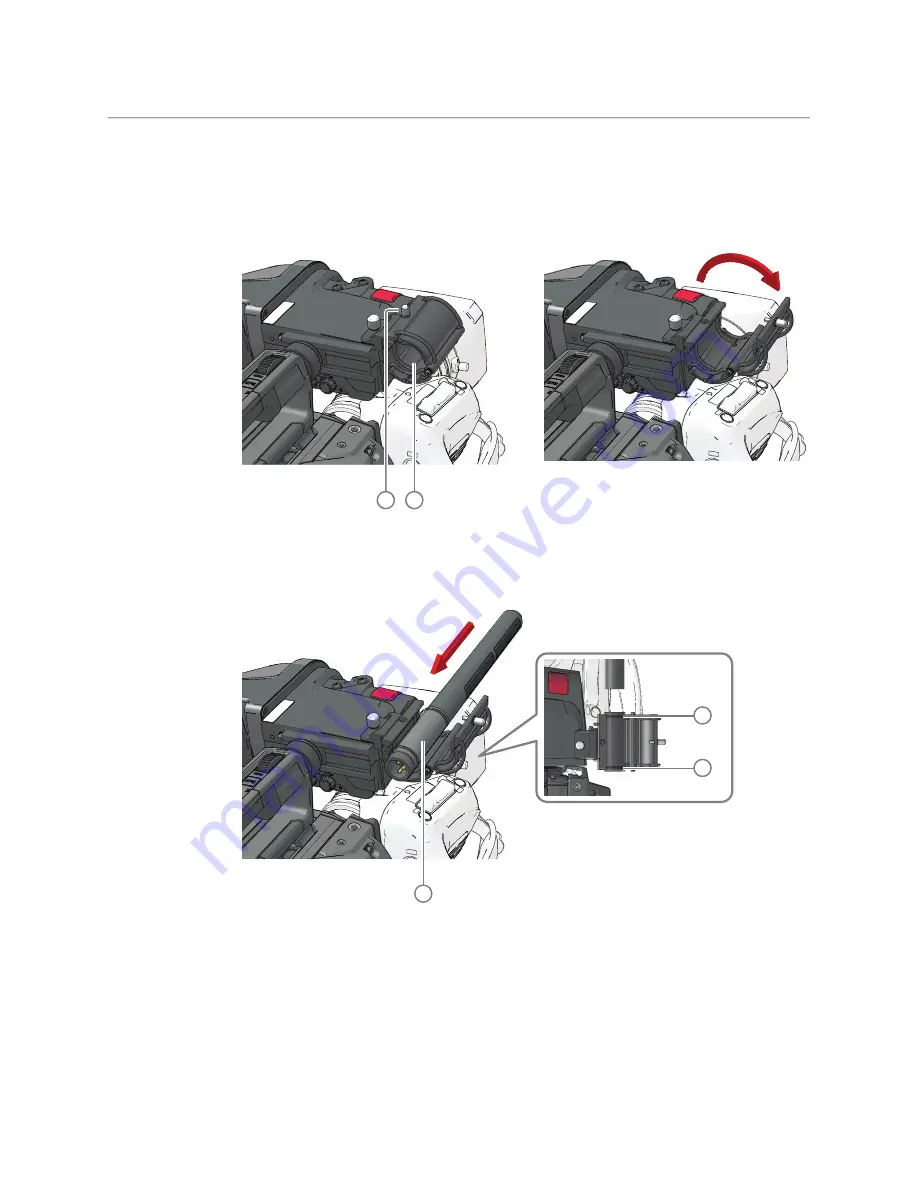
To attach a microphone to the camera proceed as follows:

• Open the microphone holder by unscrewing the knurled screw 

(1)

 of the microphone 

support bracket 

(2) 

on the viewfinder and open the bracket:

• Slide the microphone into the split tube 

(3)

 (included with the bracket) until the back 

end (connector sied) of the microphone becomes visible.

• Place the tube with the microphone into the holder with the split facing upwards. 

Mount the microphone as straight as possible.

• Ensure that the rubber supports at the back and front of the holder fit into the rims 

(4)


around the tube.

• Close the holder and tighten the knurled screw at the top. Do not allow a wind hood 

(when present) to touch the holder as this reduces the damping effect:

2

1

top view

3

4

4

Summary of Contents for LDX 150

Page 1: ...www grassvalley com LDX 150 Live Production Camera User Guide 13 00126 000 v1 0 2022 11 15 ...

Page 2: ...e without notice Terms and Conditions Please read the following terms and conditions carefully By using LDX 150 Series documentation you agree to the following terms and conditions Grass Valley hereby grants permission and license to owners of LDX 150 Series to use their product manuals for their own internal business use Manuals for Grass Valley products may not be reproduced or transmitted in an...

Page 3: ...f this symbol in or on Grass Valley equipment means that it has been tested and certified as complying with applicable Underwriters Laboratory UL regulations and recommendations for USA The presence of this symbol in or on Grass Valley equipment means that it has been tested and certified as complying with applicable Canadian Standard Association CSA regulations and recommendations for USA Canada ...

Page 4: ... atmosphere Have qualified service personnel perform safety checks after any service Cautions A caution indicates a possible hazard to equipment that could result in equipment damage Observe the following cautions when operating or working on this equipment Products that have no on off switch and use an external power supply must be installed in proximity to a main power outlet that is easily acce...

Page 5: ...amage the imagers Avoid extreme highlights as these can cause various kinds of optical reflections Be careful when connecting and disconnecting fiber cables Do not connect Grass Valley camera systems with other manufacturer s camera system parts Make connections swiftly and firmly to avoid false error messages Electrostatic Discharge ESD Protection Electrostatic discharge occurs when electronic co...

Page 6: ...n earth grounded metal frame or casing do not require any special ESD protection Environmental Information European CE WEEE directive This symbol on the product s means that at the end of life disposal it should not be mixed with general waste Visit www grassvalley com for recycling information Grass Valley believes this environmental information to be correct but cannot guarantee its completeness...

Page 7: ... Laser radiation can cause irreversible and permanent damage of eyesight Please read the following guidelines carefully Make sure that a fiber is connected to the board s fiber outputs before power is applied If a fiber cable e g patchcord is already connected to an output make sure that the cable s other end is connected too before powering up the board Do not look in the end of a fiber to see if...

Page 8: ...ble for compliance could void the user s authority to operate the equipment This device complies with part 15 of the FCC Rules Operation is subject to the following two conditions 1 this device may not cause harmful interference and 2 this device must accept any interference received including interference that may cause undesired operation Note Note This equipment has been tested and found to com...

Page 9: ...eption which can be determined by turning the equipment off and on the user is encouraged to try to correct the interference by one or more of the following measures Reorient or relocate the receiving antenna Increase the separation between the equipment and receiver Connect the equipment into an outlet on a circuit different from that to which the receiver is connected Consult the dealer or an ex...

Page 10: ... is in conformity with the relevant Union harmonization legislation and the requirements of the following directive standards RED 2014 53 EU EMC testing EN 301 489 1 V2 2 3 EN 301 489 3 V2 1 1 and EN 301 489 19 V2 1 1 EN 62311 2020 Radio testing EN 303 413 v1 1 1 GPS Radio testing EN 300 330 v2 1 1 NFC Notified body Telefication BV 0560 performed B C assessment and issued an EU type examination ce...

Page 11: ...en shall have a large area contact with the metal shell SIGNAL DATA PORTS For unconnected signal data ports on the unit fit shielding covers For example fit EMI blanking covers to SFP type ports and fit 75 Ώ RF terminators to BNC type ports COAXIAL CABLES Coaxial cables connections particularly serial digital video connections shall be made with high quality double screened coaxial cables such as ...

Page 12: ...xii Notices ...

Page 13: ...ositioning the viewfinder 9 Distance viewing 11 LDK 5301 10 Tripod adapter plate 11 Adjusting the shoulder pad 13 Adjusting the handgrip position 14 3 Configuration 15 Camera system configurations 15 NativeIP mode 15 XCU mode 16 DirectIP IP with hybrid power extender 16 Local mode 16 Control network 17 Locking 17 PTP locking 17 PTP setup 18 Local reference 18 Free running 19 Main video workflows 2...

Page 14: ... 42 Camera front panel 42 Camera left panel 44 Camera back panel 45 Controlling the camera 48 Navigating the camera menu 48 Entering the camera menu 49 Finding your way 49 Leaving the camera menu 50 Making value changes 50 Undoing changes 51 Assigning user buttons 51 Left side and lens buttons 52 Handgrip button 53 Viewfinder controls 54 Front 54 Back 55 Viewfinder information 56 Indicators 56 On ...

Page 15: ...unication 70 Managing files 70 Scene files 70 Operator files 71 Lens files 71 Media files 71 Standard files 71 6 Video setup 73 Video settings 73 Standard settings 73 Video mode 73 Sensitivity mode 73 Color bar 74 Gain 74 Optical filters 76 Exposure 76 Exposure time 76 Lighting correction 77 V Shift vertical acquisition shift 77 LED Wall Filter 78 Color 78 Color Temperature 78 Color Tint 78 Color ...

Page 16: ...r 136 Viewfinder connector 136 Right side connector panel 137 Ethernet Trunk IP connector 137 REF AES connector 138 BNC A to E connectors 138 HDMI connector 138 Back panel 139 Hybrid fiber transmission connector 139 USB connector 140 Intercom headset connector 140 Audio 1 2 input connectors 140 DC Power input connector 141 DC Power output connector 141 Auxiliary connector 142 RS 232 connector 143 ...

Page 17: ...procedure 151 Calibrations 153 Black Calibration 153 Full Black 155 Formatting the SD Card 155 Updating camera software 155 Appendix E Installation of Q SFP modules 157 Q SFP modules configurations 157 Changing Q SFP modules 157 List of Q SFP modules 160 Appendix F Specifications 163 General 163 Camera 163 Video 163 Connectivity 164 Dimensions 165 Contact Us 167 ...

Page 18: ...xviii Table of Contents ...

Page 19: ...ding check the Grass Valley website at www grassvalley com for the latest version of this user s guide and additional information User s guide updates data sheets brochures and application notes Camera software package updates release notes and installation instructions Technology Work Field The LDX 150 is designed for flexibility with the ability to be used for both dramatic productions and live ...

Page 20: ...xture a unique feature to preserve texture throughout all processing parameters Chromatic lens aberration correction CLASS offers impressive sharpness improvements on the outer regions of the image by canceling out shifts in color registration This algorithm works in conjunction with lens data using industry standard lens interface protocols Video contrast adjustment offers unmatched creative cont...

Page 21: ...ons XCU Universe UXF XF Transmission Fiber Base Station HPE 300 300 W Hybrid Power Extender with single AC mains input HPE 300 2AC 300 W Hybrid Power Extender with dual AC mains input LDK 4425 3G Fiber Power Converter unit SHED BS SMPTE Hybrid Elimination Device Base Station Camera Control components CGP 500 Creative Grading Control Panel CCS One Cameras Control Server CGA Creative Grading Applica...

Page 22: ...4 Introduction System components and accessories ...

Page 23: ... a lens To attach a lens to the camera head proceed as follows Ensure that the lens locking ring 1 is in the unlocked position turned counterclockwise If present remove the dust protection cap Slot the lens into the lens mount and make sure that lens and camera are accurately aligned Turn the lens locking ring 1 clockwise until the lens locks firmly into place Connect the lens cable 2 to the lens ...

Page 24: ...he camera menu go to the Configuration Lens Lens Settings menu and use the Lens IF Type Always place the dust protection cap when the lens is not connected to the camera EC 2 100 viewfinder Mounting the viewfinder To mount the viewfinder on top of the camera proceed as follows Loosen locking ring 2 of viewfinder support bracket 1 at the front of the camera handgrip As seen from the rear of the cam...

Page 25: ...r connector socket 4 under the recess at the right side of the camera Guide the cable through the upper cable clip 4a and down along the cable holder 4b Attach the microphone holder 5 onto the viewfinder and secure it with the knurled screw 6 on top 3 1 2 6 5 4a 4 4b ...

Page 26: ... included with the bracket until the back end connector sied of the microphone becomes visible Place the tube with the microphone into the holder with the split facing upwards Mount the microphone as straight as possible Ensure that the rubber supports at the back and front of the holder fit into the rims 4 around the tube Close the holder and tighten the knurled screw at the top Do not allow a wi...

Page 27: ...Note Note When a longer microphone is used it may not be necessary to place it in the split tube Phantom power can be switched on or off for the front microphone socket in the audio section of the camera Configuration menu Positioning the viewfinder Horizontally The horizontal position of the viewfinder can be adjusted as follows to suit your preferences Loosen the locking ring 1 As seen from the ...

Page 28: ... turning it counterclockwise using your thumb and index finger Press both sides of the handgrip clip 2 using your thumb and index finger and with the lever pressed in move the handgrip with viewfinder back or forth When the desired position is reached release the clip Note the rail on the camera body has indents so make sure to place the handgrip is placed at a fixed position Tighten the locking d...

Page 29: ...ripod the tripod plate must first be attached to the tripod Follow the tripod manufacturer s instructions to mount the wedge plate supplied with the tripod and the tripod adapter plate firmly onto the tripod Attach the camera to the tripod adapter plate as follows Slide the camera horizontally along the tripod adapter plate from back to front ensuring that the front of the camera engages the V slo...

Page 30: ...amera Ensure that the rear stud 2 is engaged and that the camera clicks into place Remove the camera from the tripod as follows Open the locking lever 5 to free the rear stud 2 Press and hold the red locking lever 3 against the release handle 4 Ensure that you have a firm hold of the camera Pull the release handle 4 forward Move the camera backwards and up 2 3 4 1 5 ...

Page 31: ...lever at the bottom left of the camera body just behind the handgrip The shoulder pad can now be moved backwards and forwards along the axis of the camera Tip Adjust the shoulder pad after all other units viewfinder lens cables have been mounted to get the best balanced shoulder position Push lever to adjust BOTTOM VIEW ...

Page 32: ...nterclockwise using your thumb and index finger Press both sides of the handgrip clip using your thumb and index finger and with the lever pressed in move the handgrip back or forth When the desired position is reached release the clip Note the rail on the camera body has indents so make sure to place the handgrip is placed at a fixed position Tighten the locking disc by turning it clockwise ...

Page 33: ...ted camera mode and system configuration An HPE 300 HPE 300 2AC Hybrid Fiber Extender An XCU UXF Series Base Station A local Power Supply Unit 300 W NativeIP mode Using a hybrid power extender Power is supplied by the HPE 300 HPE 300 2AC while optical transmission is put through from the hybrid fiber cable to single mode fiber Using a power supply unit and fiber converter Power is delivered by a p...

Page 34: ... delivered by a local power supply unit and all signals are available as local baseband connections on the camera s side and back panels LDX 150 hybrid fiber 2x single mode fiber Network Switch Hybrid to SM fiber converter or SHED C power supply unit XCU UXF hybrid fiber LDX 150 46 HPE 300 Switch SHED BS HPE hybrid fiber hybrid fiber 2x single mode fiber XCU UXF LDX 150 46 power supply unit baseba...

Page 35: ...urces a network clock using PTP typically a PTP Grandmaster over the IP Media Network a local reference source a camera or signal generator using an SDI input HD Tri Level or Composite video an XCU via the XF transmission in XCU camera mode or it can be in FreeRun mode not locked The LDX 150 can also act as a reference source to synchronize other cameras PTP locking PTP in NativeIP mode The camera...

Page 36: ...The parameters Domain Nr Delay Req Interval and Receipt Timeout must be set For more information about these paramenters refer to the IEEE1588 PTP Precision Time Protocol specification Local reference Camera The locking source is connected directly to the camera s Reference Input BNC connector see REF AES connector on page 138 1 Select the reference signal Go to the Configuration Reference functio...

Page 37: ...g diagnostics can be monitored in the Diagnostics Reference menu XCU only valid when camera is in XCU mode The locking source is directly connected to the Reference Input BNC connector on the XCU backpanel it can be either a HD Tri Level sync or Composite SD Black Burst signal In the XCU menu go to the Install Reference Source Source function and select RefVideoIn The XCU accepts and detects both ...

Page 38: ... M M M M M M M M M M M M M M M M M M M M M M M M M M M M M M M M M M M M M M M M M M M M M M M M M M M M M M M M M M M M M M M M M M M M M M M M M M M M Ma a a a a a a a a a a a a a a ai i i i i i i i i i i in n n n n n n n n n n n n n n n n n n n n n n n n n n n U U U U U U U U U U UH HD D L L L L L L L L L L L L L L L L L L L L L L L L L L L L L L L L L L L L LI I IV V V V V V V V V V VE E E E E...

Page 39: ... Main1 UHD HDR 11 1 2160p Main 2 UHD HDR 11 1 2160p Main 3 UHD HDR 11 1 2160p LIVE UHD HDR 11 1 1080p LIVE 3G HDR 2 8 Total 47 2 100G Capacity 47 Video Format Bandwidth 2110 20 1080p SDQS 2SI Main 4K 1 2 8 1080p SDQS 2SI Main 4K 2 2 8 1080p SDQS 2SI Main 4K 3 2 8 1080p SDQS 2SI Main 4K 4 2 8 1080p LIVE 3G 2 8 1080i Mon 1 4 Total 15 4 2x10G Capacity 77 IP streams from XCU to IP switch 1x speed UHD ...

Page 40: ...22 Configuration XCU mode 1X speed UHD with XCU Universe UXF ...

Page 41: ...and enter one of the following links http 10 127 44 32 camconnect http 169 254 0 201 camconnect The Camera Connect login window is shown Enter user name and password The default login name is admin and the password admin these can be changed after login Click or tap Login The Camera Connect user interface is shown Note Note All user entries in the Camera Connect application are case sensitive Clic...

Page 42: ... shown sorted by camera number Click the IP Media Port A tab here you can configure local IP addresses subnet mask and default gateway for Port A The indicator s in front of the IP addresses for port A1 and port A2 show the status of the physical IP network connection Off port is not in use indicates a connection between the port and a 10 G IP device e g a switch no connection ...

Page 43: ... IP address of Port A2 in the IP Media Network It is recommended to use an IP address in the 10 11 5 xxx range Subnet mask for most situations the subnet mask is set to 255 255 0 0 This is also the default value Default gateway for most situations the default gateway is set to 10 11 5 1 This is also the default value Note Note Do not use IP address 10 11 5 1 as it is already in use for the Default...

Page 44: ... sent as a single IP stream but with uncompressed 4K the signal is split into four sub streams Click the camera system you want to configure A popup window appears in which you can set the following parameters Main Video Enabled selects whether the Main video is included in the IP Media Network stream and to which port the stream is sent Port A Main video is routed to Port A default setting Off Su...

Page 45: ...stream Note Note When the same IP address is used for the Main video Monitoring video and or Live video streams the port numbers for each stream MUST be set to different values Main video in 4K uncompressed mode In the IP Main A tab you can set up IP addresses and port numbers for the four sub streams of the 4K uncompressed Main video outgoing stream The transport standard for Main video is also s...

Page 46: ...to which port the stream is sent Port A Main video is routed to Port A default setting Port A B Main video is routed to both Port A and B to enable redundant network operation Off Main video is NOT inserted into the IP Media Network stream this is also indicated with the indication off in front of stream 1 Standard this is the transport standard for IP Main Video Select either ST2022 6 embedded SD...

Page 47: ...ream is entered and the port number for the subsequent streams is increased by 1 Note Note This is not applicable for receivers with two 10G ports A single IP destination address causes the Ethernet switch to flood both ports with all four streams This can only be used for 25G and 40G port receivers When Manual default setting is selected you can enter the IP addresses and port numbers manually fo...

Page 48: ...er In this tab Monitoring video and or Live video outputs can be set up Note Note Live video is available as a selectable stream In HD SDR operation the video mode is the same as Main video Click the camera system you want to set up The edit popup window appears in which you can edit the following parameters ...

Page 49: ...B output Note Note Port B is only used when redundant operation is enabled Dest IP address the destination IP address for port B to which Monitoring video is sent Dest Port the destination port number for Port A for Monitoring video Live video Note Note Live video is only present when HDR is enabled and or when the XCU is running in a 4K video mode Enabled selects whether the Live video is include...

Page 50: ...nt Dest Port the destination port number for Port B for Live video IP Video In tab The list of camera systems is shown sorted by camera number In this tab the incoming External 1 External 2 and Teleprompter video inputs can be set up The Extern 1 Extern 2 and Teleprompter columns show the present indicator transport standard port number and Multicast IP address for each incoming video stream ...

Page 51: ...he incoming video stream Select either ST2022 6 or ST2110 20 Port the receiving port number for the video stream Multicast Yes or No Select whether you want to use multicast or not Multicast IP the receiving multicast IP address when Multicast Yes Tip It is recommended to use port numbers in the 1000 49152 range no indication Steam is not present or not available Yes Steam is present Unsupported f...

Page 52: ... A and B and incoming streams Click the camera system you want to set up The edit popup window appears in which you can edit the following parameters AES67 Audio Out Enabled selects whether AES67 Audio output is included in the IP Media Network stream and to which Port the stream is sent Port A AES67 Audio is routed to Port A default setting Port A B AES67 Audio is routed to both Port A and B to e...

Page 53: ...67 Audio output AES67 Audio In Present indicates whether an AES67 Audio input is present on the IP Media Network It can have the following status indications Multicast Yes or No Select whether you want to use multicast or not Multicast IP the receiving multicast IP address when Multicast Yes Channels Number of audio channels that is inserted into AES67 Audio input Can be 2 4 6 8 or 16 channels Buf...

Page 54: ...the camera system you want to set up The edit popup window appears in which you can edit the following parameters Source Selects input source for intercom Eng and Prod channels Analog from intercom subD connector at backpanel of XCU Cradle Ext1 from embedded SDI audio of external video input 1 EXT1 AES67 from AES67 Intercom stream on the IP Media Network Program source Intercom or Audio ...

Page 55: ...tput is sent Dest Port the destination port number for Port A for AES67 intercom output Port B output Note Note Port B is only used when redundant operation is enabled Dest IP address the destination IP address for port B to which AES67 intercom output is sent Dest Port the destination port number for Port B for AES67 intercom output AES67 Intercom In Present indicates whether AES67 intercom input...

Page 56: ...cated in the first group of tabs The list of camera systems is shown sorted by camera number In this tab you can set up synchronization to a PTP grandmaster Click the camera system you want to set up The edit popup window appears in which you can edit the following parameters Ch 1 Ch 2 Ch 3 Ch 4 Ch 5 to 8 16 Output stream Audio A1 Cam Audio 1 Cam Audio 2 Cam AES1 Cam AES2 digital silence Intercom ...

Page 57: ...randmaster either SMPTE2059 AES67 AES SMPTE or User When User is selected the parameters Domain Nr Delay Req Interval and Receipt Timeout must be set For more information about these paramenters refer to the IEEE1588 PTP Precision Time Protocol specification Tip Check the Apply settings to all camera systems box and press OK to apply the changed settings in this window to all camera systems where ...

Page 58: ...40 IP Media setup PTP tab ...

Page 59: ...d and the camera power switch is set to the on position When power is supplied via the hybrid fiber cable an output power socket supplies 12V 4 0 A maximum for powering accessories The power overload indicator lights up when maximum power is exceeded If excessive current flows into the camera the internal safety circuit shuts off power to all the units If this happens shut off power and check the ...

Page 60: ...when the camera is On Air 2 White Balance button Press and hold two seconds to start the Auto White Balance procedure 3 Menu Rotary and Select Turn the rotary to navigate the camera menu and push to select items 4 Back Info button Back Used when navigating the menu Info Press and hold to view information on the viewfinder screen 9 8 2 1 3 5 4 7 6 ...

Page 61: ...6 Headset volume Adjusts the overall audio volume of the intercom headset 7 Intercom Eng This button is used to activate the intercom Engineering channel talk 8 Return A This button can be assigned to an External Return Video channel 9 Return B This button can be assigned to an External Return Video channel ...

Page 62: ...s to select a color temperature preset or hold the plus to vary 3 Exposure time up down switch Press plus or minus to select an exposure time or hold the plus to set a variable exposure time Note exposure can only be changed in single speed video modes 4 Filter button Press to enter the filters selection menu and select neutral density ND and or effects FX optical filters GAIN COLOR TEMP FILTER BA...

Page 63: ...tton SW1 Assignable user button SW1 8 User button SW2 Assignable user button SW2 9 PickMe button This button can be configured to send an attention signal to the studio Camera back panel 1 Intercom Prod button This button is used to activate the intercom Production channel talk DC IN 12 17V AUDIO 2 TX LOCK CTRL CABLE IP RX DC OUT 12V 4A AUX RS 232 C2 IP AUDIO 1 2 3 5 17 16 15 14 13 11 12 10 6 7 8 ...

Page 64: ...hed on 8 Audio 2 indicator This LED lights green when the audio input is set to mic sensitivity level it lights blue when phantom power is switched on 9 Power switch Main camera power switch 10 Power out indicator This LED lights green when Power Out is available it lights red when too much power is drawn from the Power output connector overload indicator 11 Local power indicator This LED lights g...

Page 65: ...w the IP info page with more detailed info about the IP link The IP diagnose indicators stay active IP Off No Q SFP module present Red Q SFP module mismatch Yellow Q SFP module is present but no network link Green Q SFP module is present and the network link is OK RX Red Camera is not receiving IP Media data Yellow Camera is receiving errors Green Incoming IP Media data is valid TX Green Outgoing ...

Page 66: ...te Note If you cannot access some camera functions or you wish to restrict access refer to Access and security Navigating the camera menu The camera menu can be viewed in the viewfinder a connected monitor or remotely on the CGA The camera menu can be navigated by means of the menu rotary push button and back button which are located at the front of the camera The functions of the camera are group...

Page 67: ...ly five items are visible in each menu Scroll up or down to see any additional items When you first enter a menu other than the Main menu the cursor is positioned next to the first item Press the back button to go back to the menu that you were in before the current one The cursor is positioned next to the last menu You can also use the Top and Previous items to navigate These items are not immedi...

Page 68: ...t the last position of the cursor and not at the top of Main menu To prevent confusion the next time you enter the camera menu it is advisable to leave the menu by using the back button or by returning to the Main menu and selecting Menu Off Making value changes To find out where you have to go to change a function consult the camera menu reference to discover under which menu group or sub group t...

Page 69: ...utton places the cursor in front of the value and the rotary control is used to change the analog value Press the select button to return the cursor to the function list Undoing changes If you make changes to the video settings in the camera menu and you decide not to keep them use the green standard button at the side of the camera to recall a standard set of values for the video parameters Assig...

Page 70: ...m function Zoom Focus Assist FocAst Switch to Return Video A Ret A Switch to Return Video B Ret B default Production intercom Prod Engineering intercom Eng ND ND filter selection down Intercom Call Call Back for menu navigation Select for menu navigation The VTR Lens button can be assigned to Production intercom Prod default Engineering intercom Eng Viewing zoom function Zoom Switch to Return Vide...

Page 71: ...andgrip button is assigned to Switch to Return Video A Ret A default Switch to Return Video B Ret B Viewing zoom function Zoom Focus Assist FocAst The left handgrip button can be assigned to Production intercom Prod default Engineering intercom Eng 1 ...

Page 72: ...ed in the viewfinder menu 3 Front tally indicator This indicator and the one at the rear of the handgrip of the camera lights to indicate that the camera is On Air 4 Diopter adjustment ring The diopter of the viewfinder can be adjusted to suit your eyesight by turning the diopter adjustment ring Turn to the right for negative diopter values turn to the left for positive values A B 1 2 4 3 ...

Page 73: ... the tally indicators do not light even when the camera is On Air 3 User switch C underscan Set this toggle switch to On to see a scaled down to about 85 of the area picture in the viewfinder This allows for a greater viewing distance from the eyepiece A blue border around the picture and the message underscan appear Set the switch to Off to return to the original picture 4 Peaking Menu control Wi...

Page 74: ...creen indicators you want to display in the viewfinder screen The following indicators can be set up 1 Zoom indicator Shows the percentage to which the lens has been zoomed out or in ranging from 0 wide angle to 99 telezoom It shows 50 if the lens does not support this feature 2a Iris indicator Shows the iris opening or F value of the lens Typical range is from F1 4 to F25 The indicator shows Clos...

Page 75: ...icator 4a is switched on the Depth of Field indicator 4b is automatically switched off and vice versa On screen marker indicators Navigate to the Operator Toolbox Indicators menu and select the marker indicators you want to display in the viewfinder screen The following marker indicators can be set up 1 Safe Area Shows the minimum area that can be seen on a television screen Different aspect ratio...

Page 76: ...al or green tally is active 4 12 ISO indicators yellow Lights if ISO signal or Yellow On Air is active 5 13 On Air indicators red Lights if On Air is active 6 14 PickMe indicators green Lights if PickMe is active 7 Zoom indicator Lights when viewfinder zoom is active 8 Focus Assistant indicator Lights when focus assistant is active 9 ND Filter indicator Lights when a Neutral Density ND filter is u...

Page 77: ... the info button at the front or at the back panel of the camera to view information on the viewfinder screen The first info page appears in the viewfinder or monitoring channel Press the info button again to scroll through 4 pages Release the button and after a few seconds the info page disappears Page 1 IP connection page Page 2 Video and camera modes page Page 3 Basic video settings and buttons...

Page 78: ...urrent user level ULvl the last recalled operator file OpFl and the standard recall file STDOper Page 4 BNC outputs on the camera C A M 1 7 M i d f i e l d C 1 0 8 0 p 5 9 S I N o m 2 7 d B N D 1 6 4 C l e a r C T e m p 3 4 0 0 K G a m m a L i n M B l k 4 5 S W 1 C a l l S W 2 P r o d H G r i p E n g V T R L F o c A s t R E T L Z o o m R E T 2 C a l l U L v l U s e r 1 O p F l S t a n d a r d S T ...

Page 79: ...to find out how to do this The Lens menu allows you to choose and if necessary adjust other parameters to suit your lens type and your personal preferences CLASS The Chromatic Lens Aberration and Sharpness Solution CLASS compensates for chromatic aberration by using lens data Most major lens manufacturers support this feature Make sure that the lens interface is set to Digital in the Configuration...

Page 80: ... access this function Select the Auto Iris measurement area using the Area function in the Auto IRIS menu The following areas can be selected Top covers the top half of the screen or 50 of the total surface This is the default setting Spot S small center spot covers 5 Spot M medium center spot covers 10 Spot L large center spot covers 25 Full full screen measurement covers 100 Bottom covers the lo...

Page 81: ...point sets the target exposure level for Momentary Iris not a relevant setting for Auto Iris Auto Iris Gain sets the speed at which the Auto Iris reacts to changing lighting conditions 5 slow default 10 fast Extended Iris The Extended Iris function automatically adjusts the video signal level by adjusting the iris opening the gain level and the exposure time to suit the ambient lighting conditions...

Page 82: ...hen precision focus is enabled on the lens the focus frame is superimposed on the viewfinder image The frame can be moved and resized by the controls on the lens or on the focus handle An indicator in the bottom left corner of the viewfinder screen shows the current focus information Refer to the documentation of the lens manufacturer for more information about the precision focus feature Lens ind...

Page 83: ...s menu Also a delay up to 170 ms can be set The channel 1 input socket selection switch selects either the Mic connector at the front right Front of the camera or the Audio 1 connector at the rear of the camera Rear as the input for audio channel 1 Note Note A phantom power 48 VDC for the front mic socket can be set with the Configuration Audio Front Mic FrontMic Source function The audio channel ...

Page 84: ... signals are available at the XCUs intercom connector on the back panel To use the intercom system connect a headset to the XLR5 connector on the back panel of the camera An additional Tracker headset can be connected to the auxiliary connector Selection buttons and volume controls for the intercom channels can be found on the front and the back of the camera Selecting intercom channels Push the e...

Page 85: ...ght of the camera headset The routing of the intercom channels can be changed to personal preference Go to the Configuration Intercom menu to set up the routing Cam Prod selects to which ear muff s of the camera headset the production intercom channel is routed Cam Eng selects to which ear muff s of the camera headset the engineering intercom channel is routed Cam Prog selects to which ear muff s ...

Page 86: ...derneath the camera handgrip Prod Eng Eng Mode selects switching mode for the engineering channel selection button at the back panel of the camera momentary push or alternating toggle Setting up the Tracker headset Go to the Configuration Intercom Tracker menu to change settings for the Tracker headset Call button Press the Call button on the back panel to send a signal to the camera control panel...

Page 87: ...ns can be programmed as momentary default or alternating switches in the Operator Toolbox Buttons menu The indicators in the Return A and B buttons light when the video channel the respective button is assigned to is switched on PickMe button Press the yellow PickMe button on the left side of the camera or on the back panel to send an attention signal directly to the program director This function...

Page 88: ...l On Air lamp to be used For more detail and an application schematic refer to Auxiliary connector on page 142 Managing files You have access to many different files The Configuration Files menu is used to recall and store these files There are four types of files Scene files Operator files Lens files Media files A scene file contains values related to the picture performance The operator file con...

Page 89: ... on aMedia USB flash drive These files contain information for setting up the non video configuration of the camera A Standard operator file factory or customer defined is stored in the camera Note Note The standard Customer operator file is stored via the Security menu not the Files menu The decision to use the factory defined file or the customer defined file as the standard file is also made in...

Page 90: ...r the standard Operator file The contents of the customer files for both these standard files is stored via the Configuration Security menu The selection of a factory defined or a customer defined file for use as a standard file is also made in this menu You can only access the functions of the Security menu with the PIN code of the camera ...

Page 91: ...ode is used Non standard indicator The non standard indicator in the ocular viewfinder lights when one of the following conditions occur refer to the user s guide of the viewfinder for more details Extended Auto Iris is switched on AWC or FL50 FL60 color temperature is selected Video mode In the Main video menu go to Setup Video Tap the VideoMode item to select the video mode you wish to use for y...

Page 92: ...a before shooting When the color bar is selected the following functions are temporarily switched off Black Stretch White Limiter Zebra and the Safe Area and cadre indicators The lens iris closes automatically when the color bar is switched on Press the TEST button on the left side of the panel to switch on the color bar Initially the standard color bar is switched on and the button lights Press i...

Page 93: ...ly for ocular viewfinder The Gain switch can also be used to vary the Gain continuously between its minimum and maximum value Hold the plus or minus position continuously until you see the value in the viewfinder change in steps of 0 1 dB Release the switch when you reached the value you want This exits the value selection mode Using the switch momentarily again sets the Gain to the nearest preset...

Page 94: ...l path ND1 4 2 stops light reduction neutral density filter ND1 16 4 stops light reduction neutral density filter ND1 64 6 stops light reduction neutral density filter Note Note When a Neutral Density filter is selected the ND indicator in the viewfinder lights only for ocular viewfinders Four Effects FX filter positions are available Clear no filter is placed in the optical path Star 4P 4 Point S...

Page 95: ...ing that is operating at a different frequency to the camera There are two positions 50 Hz and 60 Hz Each of these positions can be varied further in a range from 10 to 10 Hz To reduce flicker select the frequency closest to the frequency of the lights and then vary the lighting control in the Production Setup Exposure Lighting menu to obtain the best result V Shift vertical acquisition shift When...

Page 96: ...the auto white measurement process The memory positions store measured values using the automatic white balance switch at the front The FL positions are recommended for shooting with fluorescent light A continuous automatic white balance position AWC is also available This function continuously measures the white balance and adjusts it accordingly It can be used when a constant color balance is re...

Page 97: ...nt light matrix is set to CoolFL and exposure to 50 Hz FL60 memory position for 60 Hz fluorescent light matrix is set to CoolFL and exposure to 60 Hz AW1 Auto White memory position 1 AW2 Auto White memory position 2 and one automatic continuous white position AWC Auto White Continuous measurement from 2000 K to 21000 K Note Note If AWC is selected the non standard indicator in the viewfinder light...

Page 98: ...te Balance If the reference color temperatures does not match your lighting conditions carry out the Auto White Balance procedure as follows 1 On the CGA go to the Color menu Color Temperature and select one of the memory positions FL50 FL60 AW1 or AW2 in which to store the measured color temperature value On the camera use the color temperature switch to select one of the memory positions FL50 FL...

Page 99: ...es 5 On the CGA tap the WHITE BALANCE button again On the camera press the WHITE BALANCE button on the front panel again to start the measurement procedure 6 A message indicating that the process is running appears Note Note If there is insufficient light the light level too low message appears in the viewfinder 7 When the process is completed within a few seconds the OK message and the measured c...

Page 100: ...uction Setup Color Color Gamut item and select REC709 for default HDTV color gamut or REC2020 for extended color gamut In HDR operation LMS is supported in addition to REC709 and REC2020 Color Protect When very bright and saturated colored lights are used predominant colors may clip This results in fully saturated areas with no detail This phenomenon occurs especially in blue and magenta color ran...

Page 101: ...e camera menu go to the Creative Control Sharpness Detail Advanced menu to find the lens related detail functions Skin Detail Skin Detail is set up to select a particular color range The Detail level within this color range can then be set independently of the rest of the picture Skin detail is mainly used to reduce the level of Detail in a person s skin tone to produce a more attractive picture D...

Page 102: ...e the iris is automatically set to auto by the camera The process running message appears 6 When the process is completed within a few seconds the OK message appears in the viewfinder 7 Now adjust the Skin Detail level with the Skin Level item Decrease the value below 50 to soften the selected area Increase the value above 50 to add extra detail Note Note In XS 6X 1080p video modes the view and th...

Page 103: ...video mode and running Auto White Balance is prohibited in Freeze Frame mode In the camera menu navigate to the Production Setup Image Control Freeze frame menu to switch Freeze Frame on or off Reverse Scan Note Note Reverse Scan is not available in high speed video modes When the camera is used at a rotated angle use the reverse scan function to rotate the camera s image to compensate In the came...

Page 104: ...86 Video setup Reverse Scan ...

Page 105: ... menu contains the functions that are used to set up the general configuration of the camera such as intercom lens settings and interfaces Diagnostics menu provides information on the current status and of the camera Service menu contains service items for advanced camera configuration The columns in the tables provide reference information about the functions in the camera menu Menu item camera f...

Page 106: ...P Settings submenu below PTP Settings available when PTP profile User GM Select Auto GM 1 GM 2 0 PTP Grandmaster selection Domain Nr 0 255 0 0 PTP Domain Number refer to IEEE 1588 for more information DelayReqInterval 4 1 3 0 PTP DelayRequestInterval refer to IEEE 1588 for more information ReceiptTimeout 2 10 2 0 PTP DelayRequestInterval refer to IEEE 1588 for more information Timing Main Video 50...

Page 107: ... Media 0 M NMOS over C2IP connector or via the IP Media Network NMOS server IP IP addr 192 168 1 2 0 M IP address for NMOS server Port Port No 6000 0 M IP port number for NMOS server IS04 ver v1 0 v1 1 v1 2 v1 3 0 M NMOS IS 04 protocol version for NMOS server ARPreq to DefGw Off On 0 M Switches ARPreq to DefGw on or off The Address Resolution Protocol ARP is used for mapping a network address to a...

Page 108: ...number for High Speed Video phase 1 Enabled No Yes 0 Enable disable High Speed Video phase 1 Phase 2 IP IP addr 224 11 5 4 0 M IP address for High Speed Video phase 2 Port Port No 20004 0 M IP port number for High Speed Video phase 2 Enabled No Yes 0 Enable disable High Speed Video phase 2 Phase 3 IP IP addr 224 11 5 5 0 M IP address for High Speed Video phase 3 Port Port No 20005 0 M IP port numb...

Page 109: ...r 10 11 8 1 0 M Source IP address for Video RX 1 Video RX 2 Enabled No Yes 0 M Enable disable Video RX 2 Multicast No Yes 0 M Enable disable Multicast for Video RX 2 IP IP addr 224 11 5 13 0 M IP address for Video RX 2 Port Port No 20013 0 M IP port number for Video RX 2 PayloadID 96 127 96 0 M Payload ID for Video RX 2 Protocol 2022 6 2110 20 0 M IP Transport Protocol for Video RX 2 Src IP IP add...

Page 110: ...ize for Intercom PayloadID 96 127 97 0 M Payload ID for Intercom Number of Ch 2 4 8 16 0 M Number of audio channels for Intercom Src IP IP addr 10 11 8 5 0 M Source IP address for Intercom Redundancy Outgoing streams Main IP IP addr 224 11 6 9 0 M IP address for Main IP Port Port No 20009 0 M IP port number for Main IP Ena No Yes 0 M Enable disable Main IP Live IP IP addr 224 11 6 10 0 M IP addres...

Page 111: ...Port Port No 20012 0 M IP port number for Video RX 2 Ena No Yes 0 M Enable disable Video RX 2 Mcast Yes No 0 M Enable disable Multicast for Video RX 2 Src IP addr 10 11 9 1 0 M Source IP address for Video RX 2 RX3 IP IP addr 224 11 6 12 0 M IP address for Video RX 3 Port Port No 20012 0 M IP port number for Video RX 3 Ena No Yes 0 M Enable disable Video RX 3 Mcast Yes No 0 M Enable disable Multica...

Page 112: ... or off Marker Type 15 9 14 9 4 3 0 O Aspect ratio of Marker Marker Style Dot Shad Both 0 O Marker style Dot dotted lines Shad shaded areas Both dotted lines and shaded areas Marker Shading Shad Black 0 O Marker Shading when marker style Shad or Both Shad transparent area Black black area Box Box 1 Box Off On 0 O Switch Box 1 on or off Type Box Line Full 0 O Box type Color White Red Green Blue Yel...

Page 113: ...y Off Top Bottom 2 O On Screen Tally signalling indicators to be displayed at the top or at the bottom of the viewfinder screen Select Off to turn the indicators off Assignments Show Hide 2 O Button Leds Off Low Medium High 2 O Brightness level of the viewfinder menu buttons Backpanel Info Leds Low High 2 Brightness level of the IP diagnose indicators on the back panel Button Illum 0 99 75 2 Brigh...

Page 114: ...limit level for Soft Detail VF Mode Combined 1 Phase 2 Phases 3 Phases 2 only for high speed video modes Method of combining high speed phases for the viewfinder output Combined all phases are combined to obtain the highest signal level for live viewing Some blurring may occur when panning or tilting 1 Phase only 1 phase is used to obtain highest sharpness but lower video levels 2 Phases same as a...

Page 115: ...ra momentary push or alternating toggle Ret A Mode Mom Alt 0 O Switching mode for the Ret A button at the front panel of the camera momentary push or alternating toggle Ret B Mode Mom Alt 0 O Switching mode for the Ret B button at the front panel of the camera momentary push or alternating toggle Back Panel Eng Mode Mom Alt 0 O Switching mode for the Eng button at the back panel of the camera mome...

Page 116: ...RetB 1 O Assigns a function to the RET 2 Lens button RET2 Mode Mom Alt 1 O Switching mode for the RET 2 Lens button momentary push or alternating toggle Viewfinder Btn 1 None Call Box1 Box2 Mono Ret A Ret B Zoom Text Tally 1 O Assigns a function to button 1 of the VF 7 100 viewfinder Btn 1 Mode Mom Alt 1 O Switching mode for button 1 momentary push or alternating toggle Btn 2 None Call Box1 Box2 M...

Page 117: ...ck Me 1 O Assigns a function to the F2 user button on the SuperXpander when present SXP F3 None ND FX Bars Prog Back Info Pick Me 1 O Assigns a function to the F3 user button on the SuperXpander when present PickMe Mode Mom Alt 1 O Selects switching mode for the PickMe buttons momentary push or alternating toggle Zoom Settings Handgrip Zoom Off On 0 O Enable disable Zoom control on top of camera h...

Page 118: ...18 dB 12 dB 2 O Gain value for preset Note Available preset values depend on the selected sensitivity mode Black Full Black Off On 3 Select to run Full Black calibration Note this takes up to 15 seconds to complete Master Black 0 99 50 2 S Master Black level this is the video level that is considered as pure black Advanced Master Black 0 99 50 3 S Master Black level this is the video level that is...

Page 119: ...surement when Area Custom Bottom 0 99 86 3 Left 0 99 24 3 Right 0 99 76 3 Average Top 0 99 27 3 Sets a custom measurement area for Auto Iris Average measurement when Area Custom Bottom 0 99 57 3 Left 0 99 5 3 Right 0 99 95 3 Peak Average 0 99 64 3 S Sets the Auto Iris measurement balance between peak and average video level Auto Iris SP 0 99 35 3 S Sets Auto Iris Setpoint Mom Iris SP 0 99 50 3 Set...

Page 120: ...acquisition timing shift on or off V ShiftTime 0 99 0 1 S Selects V Shift acquisition timing shift time ExpTime not available for high speed video modes Exp Time Sel 1 200 50 50 Hz 60 Hz Nom Var 1 Selects camera exposure time Var Exp Time 50 Hz 1000 Hz 1 Sets variable exposure time when Exp Time Sel Var in Hz or ms see below Units Hz ms 1 Selects units to use for variable exposure time LED Wall fi...

Page 121: ...ain Blue level Range 3dB 6dB 2 S Selects Gain control Painting range x 0 2 0 55 0 423 3 Displays the chromacity x value Note this is only an approximation y 0 2 0 55 0 399 3 Displays the chromacity y value Note this is only an approximation Saturation Saturation 0 200 100 2 S Sets color saturation level 0 fully desaturated black white 100 normal saturation 200 maximum saturation HDR Saturation 0 2...

Page 122: ...0 S S Sets Red into Blue coefficient when Matrix is set to variable G B 0 99 50 S S Sets Green into Blue coefficient when Matrix is set to variable Image Control Freeze Off On 2 Switches image freeze on or off Use to assist off line setup and configuration Reverse Scan Reverse Scan Off On 0 S Switches Reverse Scan on or off Mode Horiz Vert Both 0 S Selects Reverse Scan mode Horiz the image is flip...

Page 123: ...0 User Guide Sensitivity Nom HiQ HiSens 3 S Sensitivity mode HiQ High quality Nom Nominal HiSens High sensitivity Note Sensitivity mode is not available for high speed video modes Function Values U F Description ...

Page 124: ...w Off On 3 Switch on to view the selected color area in the main signal VF View Off On 3 O Switch on to view the selected color area in the viewfinder Set 1 2 3 4 5 6 3 Selects a color correction set Set On Off Off On 3 Switches the selected color corrector set on or off Note when off settings can not be changed Color 0 359 99 0 3 Sets the color area by hue in steps of 22 5 degrees Width 22 5 360 ...

Page 125: ... Detail Level above Level Dep 0 99 30 3 S Sets the detail reduction level for shadow areas Noise Slicer 0 99 10 3 S Sets the level of the noise slicer for Detail Dtl Flw Gain Off On 3 S When switched on Detail level follows Gain level Dtl Flw Zoom Off On 3 S When switched on Detail level follows Zoom factor HDR Detail Detail Off On 3 S Switches HDR Detail on or off Detail Level 0 99 50 2 S Sets th...

Page 126: ...tail Source R G R G Y 3 Selects the video component that is used to generate HD Detail signal Soft Detail Off On 3 Switches Soft Detail on or off Soft Detail Lvl 0 99 50 2 Sets the level of Soft Detail added to the video signal Advanced Vert Detail Lvl 0 99 25 3 Sets the level of the vertical component in the Detail signal Coarse Fine 0 99 90 3 Sets detail balance between coarse and fine structure...

Page 127: ...l Blue for Skin Gate 1 Color1 Red 0 99 37 3 S Sets color level Red for Skin Gate 1 Color1 Blue 0 99 6 3 S Sets color level Blue for Skin Gate 1 Width2 Red 0 99 29 3 S Sets width level Red for Skin Gate 2 Width2 Blue 0 99 40 3 S Sets width level Blue for Skin Gate 2 Color2 Red 0 99 37 3 S Sets color level Red for Skin Gate 2 Color2 Blue 0 99 6 3 S Sets color level Blue for Skin Gate 2 Width3 Red 0 ...

Page 128: ...hen the STD File Green button is pressed Fact Factory default Scene file Cust Customer Scene file Std Oper File Fact Cust S Selects the Operator file to be recalled when the STD File Green button is pressed Fact Factory default Operator file Cust Customer Operator file Scene File Yes No S Determines if the Scene file should be recalled when the STD File Green button is pressed Oper File Yes No S D...

Page 129: ... the selected Scene file Recall File Select MCam1 MCam2 MCam3 MCam4 S Selects a Media File for recall Recall Exec S Recalls the selected Media file to the camera This overwrites current Media settings Operator FIles Store File Select Standard OCam1 OCam2 OCam3 OCam4 2 Selects a Operator File for storing Store Exec 2 Stores the Operator settings in the selected Scene file Recall File Select Standar...

Page 130: ...CU mode ConnectType Cable DirectIP DirectIP 2 Select Connect Type Cable XCU mode DirectIP or DirectIP Note the DirectIP license is required 2ry Stream 3 XCU Name name 2 In DirectIP DirectIP mode this is the name of the XCU that the camera connects to Note the DirectIP license is required Disable Camera Off On 0 Locks all camera buttons to prevent operational mistakes Lens Lens Settings Lens Connec...

Page 131: ...ration data from lens No Info lens does not support Unsup CLASS cannot be activated I F NOK Lens interface not OK no lens found connected or analog lens interface in use Off CLASS is switched off Progress 0 100 0 0 Shows progress of the lens CLASS data reading process Shading Shading Off On S Switches lens shading compensation on or off R Saw H 0 99 50 S Sawtooth Horizontal for Red channel R Par H...

Page 132: ...d 1 Selects the camera operator s microphone routing Off no routing Switch Track route signal to Tracker channel Prod route signal to Production channel Cam Mic Level 22dB 28dB 34dB 40dB 46dB 52dB 58dB 64dB 1 Selects Mic level of camera operator s intercom microphone Cam Mic Power Off On 1 Switches bias tee power 12 VDC to camera operator s intercom microphone on or off Cam Prod Off Left Right Bot...

Page 133: ...et the program intercom is routed Tracker ProgExt Off Left Right Both 1 Tracker Cam Off Left Right Both 1 Selects to which ear muff s of the Tracker headset the camera headset microphone signal is routed Tracker Lvl 0 99 75 1 Sets Tracker headset level Tracker Boost Off On 1 Audio Audio Gain Mode Local Extern 1 Loc local audio gain level is controlled by the settings in this menu Extern external a...

Page 134: ...c Mic48V 1 Selects source input sensitivity for the Audio 2 either Line or Mic level or Mic level with phantom power Audio 2 Level 22dB 28dB 34dB 40dB 46dB 52dB 58dB 64dB 1 Selects input gain level for Audio channel 2 when Audio Gain Mode is set to Local Note when Audio Gain Mode is set to Extern al Audio 2 Level is set by the XCU Audio 2 HPF Off On 1 Switches High Pass Filter for Audio channel 2 ...

Page 135: ...ber 1 99 1 0 Selects logical camera number IP Settings IP Mode DHCP Auto Manual 0 Selects automatic manual or DHCP IP mode for C2IP network Subnet Mask 0 31 0 0 Selects the subnet mask when IP mode is set to manual IP IP address 0 Sets camera IP address in the C2IP network when IP mode is set to manual Def GW GW address 0 Selects camera head default gateway IP address in the C2IP network when IP m...

Page 136: ...ses 0 In high speed video modes this selects the BNC Outputs Profile for the signals on BNC A to BNC D default Live Live2K are output Ext and SDI phases Live Combined plus Phases are output BNC A Preset Live4K Live2K 0 In high speed video modes and when the BNC Outputs Profile is set to Phases this selects which Live signal is output on BNC A BNC C Preset Off Ext1 Ext2 Ext3 TP 0 External video or ...

Page 137: ...able 2 Shows status of the Native IP license Time Left 0 sec 65535 sec 0 sec 2 Shows time left in seconds for the Native IP license Direct IP Unknown Not Applicable 2 Shows status of the Direct IP license Time Left 0 sec 65535 sec 0 sec 2 Shows time left in seconds for the Direct IP license GPS Unknown Not Applicable 2 Shows status of the GPS license Time Left 0 sec 65535 sec 0 sec 2 Shows time le...

Page 138: ...o Yes 2 Find licenses Search Next Exec 2 Add License Exec 2 Type None GPS NativeIP UHD 1x UHD 3x UHD FilmC UHD FilmB DirectIP 2 Start 2 Time Zone UTC 12 00 UTC 11 00 UTC 01 00 2 Duration 0 65535 day 0 day 2 Trial license SelectType None GPS NativeIP UHD UHD_3X DirectIP 2 Activate Exec 2 Time left 0 sec 65535 sec 0 2 Function Values U F Description ...

Page 139: ...address 192 168 1 1 2 Domain IP address 2 Hostname name 2 Ethernet MAC Address 00 00 00 FF FF FF 2 Shows hardware MAC address of the camera Link State Connected Disconn 2 Shows link status of the Ethernet connection Link type Unknown 10Mb Half 10Mb Full 100Mb Half 100Mb Full Negotiate 2 Show link type speed of the Ethernet connection Loopback test Loopback test Off On S Data count nnn S Date error...

Page 140: ...s No 1 TX Mb s nnn 1 RX Mb s nnn 1 RX Error nnnn 1 RX Error sec nnnn 1 FEC Corrected nnnn 1 FEC Ok nnnn 1 SFP1 present Yes No 1 Type Unavail Unknown 100G 10G 40G Act_40G 1 Los Ok NotOk 1 Link Yes No 1 Speed Unsup 10G 25G 1 TX Mb s nnn 1 RX Mb s nnn 1 RX Error nnnn 1 RX Error sec nnnn 1 FEC Corrected nnnn 1 FEC Ok nnnn 1 SFP2 present Yes No 1 Type Unavail Unknown 100G 10G 40G Act_40G 1 Los Ok NotOk...

Page 141: ...ink RX1 RX2 RX3 RX4 1 TxPower 100dBm 100dBm 0 dBm 1 RxPower 100dBm 100dBm 0 dBm 1 Los Yes No 1 Rx Cdr Lock Yes No 1 Tx Cdr Lock Yes No 1 Media Network Vlan C2IP Packets Rx nnnn 0 C2IP Packets Tx nnnn 0 Trunk Packets Rx nnnn 0 Trunk Packets Tx nnnn 0 Outgoing Streams Main video Unsup Yes No 0 Live Video Unsup Yes No 0 Audio Unsup Yes No 0 Intercom Unsup Yes No 0 Incoming Streams Video RX 1 Stream A...

Page 142: ...25 4K23 1 Video RX 3 Stream Active Yes No 1 Pkts in Buffer nnn 1 VideoMode Unknown SD 1080i59 1080i50 720p50 720p50 1080pfs23 1080p59 1080p50 4K59 4K50 4K47 4K29 4K25 4K23 1 Audio Stream Active Yes No 1 Profile Ok NotOk 1 Intercom Stream Active Yes No 1 Profile Ok NotOk 1 Redundancy Outgoing Streams Main Video Unsup Yes No 0 Live Video Unsup Yes No 0 Audio Unsup Yes No 0 Intercom Unsup Yes No 0 In...

Page 143: ...com Stream Active Yes No 1 Stream Valid Ok NotOK 1 PTP Status Listening Calibrating Locked GM found Off 1 Path Delay nnn 1 Offset to Master 30000 30000 0 1 Selected GM None GM 1 GM 2 1 GM 1 Info ID text 1 ID of the PTP Grandmaster to which the camera is locked IP IP address 1 IP address of the PTP Grandmaster to which the camera is locked Status Listening Calibrating Locked Off 1 Locking status of...

Page 144: ...rence UserSelect SDI Input PTP TriLvl Composite FreeRun 0 Reference signal or source to lock the camera to note this is the same function as Configuration Reference Lock Source Unknown SDI Input PTP TriLvl Composite XF FreeRun 0 Source to which the camera is currently locked Lock Standard Unknown 1080i59 1080i50 720p59 720p50 1080p59 1080p50 PAL NTSC SD 4K50 4K59 0 Video mode standard to which the...

Page 145: ...ode Unknown SD 1080i59 1080i50 720p50 720p50 1080pfs23 1080p59 1080p50 4K59 4K50 4K47 4K29 4K25 4K23 1 HDMI Connected Yes No 0 VideoMode Unknown 1080P50 1080p59 4K25 4K29 4K50 4K59 0 SampleFormat RGB YCrCb 0 Bits 8 10 12 0 HdrMode SDR PQ HLG 0 XF Transmission System Locked No Yes 0 Fiber Fib B XCU CAM Cable Status OK Critic Error NoSig 0 Signal Status OK Critic Error NoSig 0 RX Margin 100 dB 100 d...

Page 146: ... 0 Transm Details Fiber Rx Margin S Signal Err Cnt S Ethernet Err sec S Eye Value S Ethernet Load Rx Mb sec S Tx Mb sec S Ethernet Packets valid sec S error S error sec S FEC Corr S FEC Corr sec S Ethernet Network Status S IP RX Info Loc IP S Port_Ch0 S IP TX Info IP_Ch0 S Port_Ch0 S Stream Locked S Stream RxBuf_1 S Stream RxBuf_2 S Stream RxBuf_3 S Streams Tx Available S Function Values U F Descr...

Page 147: ...Packets S Tx Packets S C2IP Trunk Rx Packets S Tx Packets S Audio FrontMic Lvl 127 0 127 0 Audio1 Lvl 127 0 127 0 Audio2 Lvl 127 0 127 0 Audio3 Lvl 127 0 127 0 Audio 4 Lvl 127 0 127 0 Configuration Camera Type PID Alias Device ID Number Number MPB Image MPB Config TXB Image TXB Config Viewfinder Type XCU Type Function Values U F Description ...

Page 148: ...ilent Default Cool 2 Manual Speed 3000 rpm 9000 rpm 6000 rpm 2 Fan Speed Temp C Camera 128 C 127 C 0 C 2 MPB FPGA 128 C 127 C 0 C 2 Sitara 128 C 127 C 0 C 2 TXB FPGA 128 C 127 C 0 C 2 Front 128 C 127 C 0 C 2 Sensor Red 128 C 127 C 0 C S Sensor Green 128 C 127 C 0 C S Sensor Blue 128 C 127 C 0 C S Backpanel 128 C 127 C 0 C 2 Temp F Camera 197 F 261 F 0 F 2 MPB FPGA 197 F 261 F 0 F 2 Sitara 197 F 26...

Page 149: ...in 0 dB 6 dB 0 dB S Blue Sensor Imager Gain 0 dB 6 dB 0 dB S Status PCB Status Board 2 PID 2 Code 2 Rev Ed 2 System Status Unknown OK Illegal Illegal 2 SXP Status SXP SW 12NC 2 SXP SW Status 2 SXP Detect Yes No S SXP Power On Yes No S SXP SW Version S Status State NoAccess Recovered Init Valid S Oper Hours 0 65535 0 S Oper Hours SXP 0 65535 0 S Power Cycles 0 65535 0 S Minimum Temp 128 C 127 C 0 C...

Page 150: ...132 Menu references Diagnostics menu High Temp Warn 0 65535 0 S Function Values U F Description ...

Page 151: ...ostics file Usage Info No Yes S SelectYes to include Usage Info in diagnostics file Network Info No Yes S SelectYes to include Network Info in diagnostics file Storage None SDcard USB SD USB S Selec storage space for diagnostics files Write Files Exec Busy Abort S Shows writing status Current File None Config Usage NetWork Settings AppLog S Shows file currently being written to storage space SD Ca...

Page 152: ...to complete Status Unknown OK Error Fatal Error Needed Temp Low Temp Unst TimeOut Temp Range FullBlRec Filter Cap Running Ready Failed Aborted 3 Shows status of the Black Calibration procedure Progress 0 100 3 Progress of Black Calibration procedure Act Temp 128 C 127 C 3 Shows actual current camera temperature White Calibr User Calibr Off Running S Select to run User White Calibration Status Unkn...

Page 153: ...135 B Connectors Right front side Lens connector view finder connector Front Mic connector Bottom view ...

Page 154: ...1 A 1 12 pin Hirose male connector panel view Pin Description 7 Iris follow 8 Lens servo 9 Range Extender 10 Zoom follow 11 RxD Focus follow 2 12 TxD 5 10 6 1 7 8 2 9 11 3 4 12 1 If more than maximum power is drawn from the lens connector the camera automatically shuts off power to the lens A message Lens Power Error is shown in the viewfinder 2 Focus Follow is not a default function of all lens t...

Page 155: ...AES BNC BNC A BNC B BNC D BNC C HDMI BNC E Pin Description 1 Transmit Data 1 TX_D1 2 Transmit Data 1 TX_D1 3 Receive Data 2 RX_D2 4 BI_D3 5 BI_D3 6 Receive Data 2 RX_D2 7 BI_D4 8 BI_D4 8 pin standard RJ 45 ethernet connector panel view Ethernet 10 100 1000 Base T compliant with IEEE 802 3 edition 2000 ...

Page 156: ...connector panel view These BNC connectors can be programmed for different video output signals Refer to Appendix C for more information about the video signals on these connectors Pin Description 1 Hot Plug Detect 2 Reserved 3 TDMS Data 2 4 TDMS Data 2 Shield 5 TDMS Data 2 6 TDMS Data 1 7 TDMS Data 1 Shield 8 TDMS Data 1 9 TDMS Data 0 10 TDMS Data 0 shield Micro HDMI type D connector panel view Pi...

Page 157: ...USB connector Intercom headset connector Audio 2 input Audio 1 input C2IP connector RS 232 connector Auxiliary connector DC Power Output DC Power Input Hybrid fiber transmission connector Pin Description 1 Optic Fiber channel A 2 Power supply return 3 Optic Fiber channel B 4 Power LEMO SMPTE304M Hybrid fiber connector 2 1 3 4 Manufacturer code LEMO 3K 93C ...

Page 158: ...n 4 Telephone left 5 Telephone right XLR 5 pin female connector panel view Microphone level 64 dBu 24 dBu switchable Microphone impedance 600 Ω Output level 6 dBu nominal Output impedance 50 Ω 2 3 1 4 5 Pin Description 1 Audio shield 2 Audio In 1 3 Audio Return XLR 3 pin female connector panel view 3 1 2 Microphone impedance 200 Ω Phantom power 48 V switchable Sensitivity range Mic from 22 dBu to ...

Page 159: ...age must not exceed 17 V total input current must be 16A 3 2 4 1 Pin Description 1 GND Pins 1 2 are bridged 2 GND 3 13 to 17 V Pins 3 4 are bridged 4 13 to 17 V XLR 4 pin female connector panel view NOTE DC Power is not available when the camera is locally powered by the DC Power input connector When more than 4 A current is drawn from this connector the power overload indicator located next to th...

Page 160: ...ion 20 On Air signal Manufacturer code of the mating cable plug connector HR10A 13P 20P C Below is an example for the wiring of the auxiliary connector 1 20 680 Green Power Call ENG PROD Ret B Ret A Green Call Select Yellow ISO Down Up Red On Air 1 Return A 2 Return B 3 Tracker intercom to Prod 4 Tracker intercom to Eng 5 Tracker telephone Left 4 XLR 5 headphones 3 XLR 5 headphones 5 XLR 5 headpho...

Page 161: ...erial connection 1 can be used for serial private data Serial connection 2 can be used for pan and tilt systems Signals are at RS 232 levels 115 kB s max Mating cable plug connector HR10A 7P 6P C Pin Description 1 Transmit Data 1 TX_D1 2 Transmit Data 1 TX_D1 3 Receive Data 2 RX_D2 4 BI_D3 5 BI_D3 6 Receive Data 2 RX_D2 7 BI_D4 8 BI_D4 8 pin standard RJ 45 ethernet connector panel view Ethernet 10...

Page 162: ...144 Connectors C2IP Ethernet connector ...

Page 163: ...te the camera in the desired mode s Baseband video signals Baseband signals are available in all available camera modes at the BNC connectors panel on the camera No installed Q SFP modules are required Note Note High Speed 3X video modes are not available when the camera is in XCU mode 4K video modes 4K150 179 3X 4K50 59 1X Required option license UHD 3X UHD 3X UHD 1X BNC Outputs profile1 Phases D...

Page 164: ...vel B is converted to level A as input for the internal video router BNC B Phase 1 out 2160p 12 Gb s ST2082 HDR only Live2K 1080i 1 5Gb s ST292M or 1080p 3Gb s ST425 1 HDR or SDR3 Live2K 1080i 1 5Gb s ST292 M or 1080p 3Gb s ST425 1 HDR or SDR3 BNC C Phase 2 out 2160p 12 Gb s ST2082 HDR only Ext1 2 or 3 out4 SD 270 Mb s ST259M or 720p 1080i 1 5Gb s ST292M or 1080p 3 Gb s ST425 1 or 2160p 12 Gb s ST...

Page 165: ...92M ST2741 HDR or SDR2 BNC C Ext1 2 3 out 2160p 59 not for Ext3 1080p 59 1080psF 29 ST274 Annex A or 1080i 59 Ext1 2 3 out 2160p 50 not for Ext3 1080p 50 1080psF 25 ST274 Annex A or 1080i 50 Ext1 2 3 out 2160p 59 not for Ext3 1080p 59 1080psF 29 ST274 Annex A or 1080i 59 BNC D Ext1 2 3 out 2160p 59 not for Ext3 1080p 59 1080psF 29 ST274 Annex A or 1080i 59 Ext1 2 3 out 2160p 50 not for Ext3 1080p ...

Page 166: ...deo modes Video mode 4K150 179 3X 4K50 59 1X Required option license NativeIP UHD 3X NativeIP UHD 1X Required Q SFP module 100G 25G Outgoing streams Cam to IP 4K Phase 1 2160p 11 1 Gb s ST2110 22 HDR only 4K 2160p 11 1 Gb s ST2110 22 HDR only 4K Phase 2 2160p 11 1 Gb s ST2110 22 HDR only 4K Phase 3 2160p 11 1 Gb s ST2110 22 HDR only Live4K 2160p 11 1 Gb s ST2110 22 HDR only Live2K 1080p or 1080i1 ...

Page 167: ...d Q SFP module 10G 25G 100G 10G 25G 100G 10G 25G 100G Outgoing streams Cam to IP Main Video 2160p 23 98 ST2110 20 Main Video 2160p 25 ST2110 20 Main Video 2160p 29 97 ST2110 20 Live Video 1080p 23 98 ST2110 20 Live Video 1080p 25 ST2110 20 Live Video 1080p 29 97 ST2110 20 Incoming streams IP to Cam Ext1 2160p 59 1080p 59 1080psF 29 ST274 Annex A or 1080i 59 HDR only Ext1 2160p 50 1080p 50 1080psF ...

Page 168: ...nd required bandwidth Refer to Appendix E for more information about installing Q SFP modules on the camera IP streams in XCU mode In XCU mode video signals are available as IP streams on the IP Media Network that is connected to the IP Media Bay on the back panel of the XCU Refer to the XCU UXF Series user s guide for an overview of available video streams Note Note Make sure that you have instal...

Page 169: ... file s from a compressed zip archive before proceeding Using a USB Flash Drive Copy the license file to the root directory of a USB Flash Drive and insert the USB Flash drive into the USB connector at the back panel of the camera head Note Note The file system of the USB Flash Drive must be FAT32 Adding licenses 1 In the camera menu navigate to the Licenses New Licenses menu 2 Check the time date...

Page 170: ...censes Planned Licenses menus NFC Feature NFC stands for Near Field Communication which allows the camera to communicate with an NFC enabled device like a smartphone For the LDX 100 Series Grass Valley created the LDX Scanner a free of charge application app for NFC enabled smartphones both Android and IOS The LDX Scanner app of the smartphone powers the NFC chip in the camera also when the camera...

Page 171: ...com are a good source to find the correct date and time in a given time zone Trial licenses Trial licenses can be activated at any time they expire after 3 minutes You do not need a license file to activate them To activate a trial license navigate to the Licenses Trial Licenses menu and switch on the license you want to use Running a trial license is a good way of checking if your camera system i...

Page 172: ...The camera starts to warm up or cool down depending on the ambient temperature and the selected calibration temperature The lens is capped automatically and lens iris is closed during the calibration process The Actual current temperature can be monitored using the Act Temp item When the camera reaches the selected calibration temperature the Black Calibration process starts It takes up to 80 seco...

Page 173: ...ility of video modes depend on installed licenses Formatting the SD Card In some situations it may be necessary to format the camera s internal storage SD Card To format the SD Card proceed as follows Switch on the camera Note Note The user level must be set to Service to access the Service menu In the camera menu go to the Service SD Card Format item and select it The formatting process starts It...

Page 174: ...156 Procedures Updating camera software ...

Page 175: ...e camera Use a Torx T10 screwdriver to loosen the four captive screws from the right side panel of the camera as indicated below Lift the panel by using the small recess at the left Remove the panel The optic cabling and Q SFP module s become visible Q SFP module configuration Workflow Camera mode none Local baseband mode none 1 1x 10G SFP or 10 25G dual rate SFP Legacy XCU modes XCU 1 1x 25G SFP ...

Page 176: ...rrule ends keep clean Carefully remove the inserted Q SFP module s from their case s If two SFP modules are inserted remove them one by one If needed place the new Q SFP module s into the suitable cage s Unused Q SFP modules can be left in their cage the camera automatically switches off all unused modules AFTER placing the Q SFP module s insert the fiber cables according to the desired configurat...

Page 177: ...r A into the top LC socket of the SFP module and insert fiber B into the bottom LC socket of the SFP module Configuration 2 2x 25G BiDi SFP modules Insert fiber A into the top LC socket of the SFP module and insert fiber B into the top LC socket of the SFP module QSFP cage SFP 1 cage SFP 2 cage QSFP cage SFP 1 cage SFP 2 cage ...

Page 178: ... of Q SFP modules The following Q SFP modules have been released for use with the LDX 150 Note Note All listed modules have industrial specifications Refer to your Grass Valley sales representative for availability and prices QSFP cage SFP 1 cage SFP 2 cage manufacturer part number module type description Eoptolink EOLP 1325G 10 RI 25G 10G SFP SM 10 km 1310 nm Single Mode 1310 nm SFP28 Transceiver...

Page 179: ...161 LDX 150 User Guide Note Note Make sure that the matching other end Q SFPs in the IP switch have the same specifications ...

Page 180: ...162 Installation of Q SFP modules List of Q SFP modules ...

Page 181: ...ical filters First wheel Clear 1 4 ND 1 16 ND 1 64 ND capped Second wheel Clear 4 point star Soft focus Fixed 2 5µ Optical Low Pass filter Electronic color correction 3200 K 5600 K 7500 K FL 2 AWB presets Variable Continuous Auto White Exposure Electronic exposure down to 1 1000 s in single speed operation S N ratio typ 62 dB in 1080p50 59 video modes sensitivity mode Nominal Sensitivity 2000 lux ...

Page 182: ...thernet IP Trunk RJ 45 Ethernet connector 1 Gb s Lens connector 12p Hirose connector Viewfinder connector 9p Fischer MiniMax connector Monitoring video Micro HDMI type D connector Hybrid Fiber connector SMPTE 304M hybrid fiber connector swiveling Mounting holes 2x 20 UNC 3x M4 threaded holes camera thread Audio inputs rear 2x XLR 3 female balanced with 48 V phantom power Intercom XLR 5 with Engine...

Page 183: ...165 LDX 150 User Guide Dimensions 166 5 mm 252 3 mm 379 7 mm 92 7 mm 74 mm 153 3 mm 93 mm 5 mm ...

Page 184: ...166 Specifications Dimensions ...

Page 185: ...in a local phone number for the support center nearest you please consult the Contact Us section of Grass Valley s website www grassvalley com An online form for e mail contact is also available from the website Corporate Head Office Grass Valley 3499 Douglas B Floreani St Laurent Quebec H4S 2C6 Canada Telephone 1 514 333 1772 Fax 1 514 333 9828 www grassvalley com ...

Reviews: