FC7000-UM-251-9370
7-30
7. ADJUSTMENT
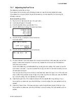
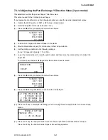
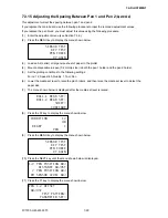
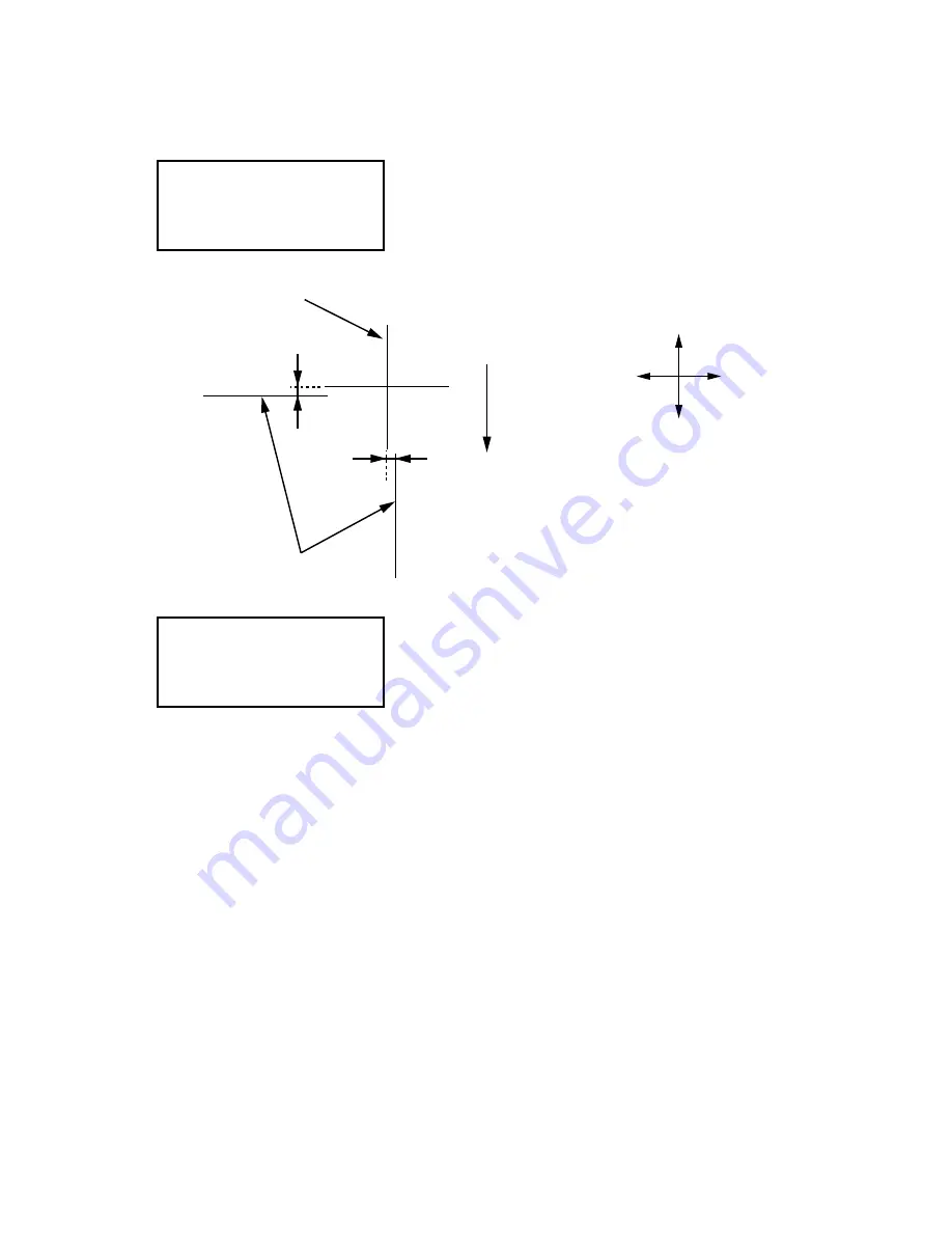
(12) Use the ARROW keys to move the pens to an open area to plot the cross marks.
(13) Press the F3 key to plot the cross marks by pen 1 and pen 2 shown below.
When they have been plotted, the menu shown below is displayed.
PEN 1-2 OFFSET
ADJUST
TEST PATTERN>
PARAMETER SET>
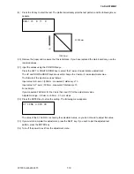
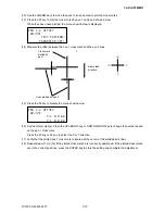
(14) Measure the offset between the pen 1 cross mark and the pen 2 lines.
Media feed
direction
Lines plotted by pen 2
Cross mark
plotted by
pen 1
Y
X
+Y
-Y
+X
-X
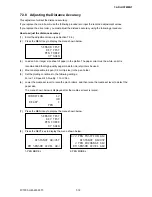
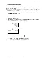
(15) Press the F4 key to display the menu shown below.
PEN 1-2 OFFSET
ADJUST
X=+ 0.0 mm
Y=+ 0.0 mm
(16) Set the offset value(s). Press the UP ARROW key or DOWN ARROW key to change the number based
on the pen 1 cross mark.
Press the F3 key or F4 key to select the X or Y direction.
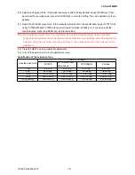
(17) Verify that the plotted pen 1 cross mark is located at the center of the plotted pen 2 lines.
(18) Repeat steps (13) to (16) if the plotted cross marks are incorrectly positioned. If the plotted cross marks
are in the correct positions, press the ENTER key to store the setting and complete the adjustment.
Summary of Contents for FC7000-100
Page 2: ......
Page 8: ......
Page 34: ......
Page 38: ......
Page 100: ......
Page 110: ......
Page 112: ...FC7000 UM 251 9370 10 2 10 PARTS LIST 1 2 3 4 5 6 7 8 10 9 Control Panel Assy 11 12...
Page 114: ...FC7000 UM 251 9370 10 4 10 PARTS LIST Control Panel 5 4 3 6 9 8 7 1 1 2 3 5 10...
Page 126: ......
Page 141: ...FC7000 UM 251 9370 11 15 11 BLOCK DIAGRAMS AND CIRCUIT DIAGRAMS 11 3 2 Main Board CPU...
Page 142: ...FC7000 UM 251 9370 11 16 11 BLOCK DIAGRAMS AND CIRCUIT DIAGRAMS 11 3 3 Main Board FPGA...
Page 143: ...FC7000 UM 251 9370 11 17 11 BLOCK DIAGRAMS AND CIRCUIT DIAGRAMS 11 3 4 Main Board I F...
Page 144: ...FC7000 UM 251 9370 11 18 11 BLOCK DIAGRAMS AND CIRCUIT DIAGRAMS 11 3 5 Main Board Motor Drive...
Page 145: ...FC7000 UM 251 9370 11 19 11 BLOCK DIAGRAMS AND CIRCUIT DIAGRAMS 11 3 6 Main Board Memory...
Page 146: ...FC7000 UM 251 9370 11 20 11 BLOCK DIAGRAMS AND CIRCUIT DIAGRAMS 11 3 7 Main Board Power Supply...

