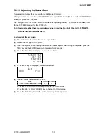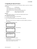
FC7000-UM-251-9370
7-17
7. ADJUSTMENT
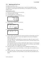
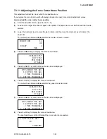
(10) Adjust the 300g-pen force. If the measured value is within the specification range (300±20g) or if you
have input the recorded value, press the ENTER key to store the setting. The next specified pen force
appears.
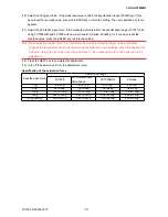
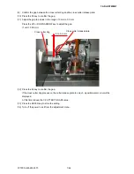
(11) Adjust the 450 (400) g-pen force. If the measured value is within the specification range (FC7000: 450
±20g, FC7000Mk2 and FC7000 with new main board, 9 Series: 400±20g ) or if you have input the
recorded value, press the ENTER key to store the setting.
Note: When adjusting the pen force, it is important to do it quickly. Delaying the pen force adjustment
changes the temperature of the actuator and causes artificially lower readings. When this happens the
actual pen force may be higher than the specification. This is especially true for the upper pen force
adjustment.
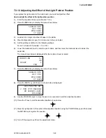
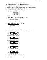
(12) Press the NEXT key to complete this adjustment.
(13) Turn off the power to exit from the adjustment menu.
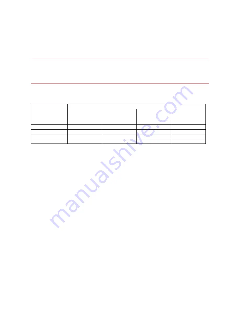
Specification of the actual pen force
Specified pen force
Actual force range
FC7000
FC7000 with new
Main boaed
FC7000MK2
9 Series
10g
8 to 12g
8 to 12g
8 to 12g
8 to 12g
40g
36 to 44g
36 to 44g
36 to 44g
36 to 44g
120g
110 to 130g
110 to 130g
110 to 130g
110 to 130g
300g
280 to 320g
280 to 320g
280 to 320g
280 to 320g
450g (400g)
430 to 470g
380 to 420g
380 to 420g
380 to 420g
Summary of Contents for FC7000-100
Page 2: ......
Page 8: ......
Page 34: ......
Page 38: ......
Page 100: ......
Page 110: ......
Page 112: ...FC7000 UM 251 9370 10 2 10 PARTS LIST 1 2 3 4 5 6 7 8 10 9 Control Panel Assy 11 12...
Page 114: ...FC7000 UM 251 9370 10 4 10 PARTS LIST Control Panel 5 4 3 6 9 8 7 1 1 2 3 5 10...
Page 126: ......
Page 141: ...FC7000 UM 251 9370 11 15 11 BLOCK DIAGRAMS AND CIRCUIT DIAGRAMS 11 3 2 Main Board CPU...
Page 142: ...FC7000 UM 251 9370 11 16 11 BLOCK DIAGRAMS AND CIRCUIT DIAGRAMS 11 3 3 Main Board FPGA...
Page 143: ...FC7000 UM 251 9370 11 17 11 BLOCK DIAGRAMS AND CIRCUIT DIAGRAMS 11 3 4 Main Board I F...
Page 144: ...FC7000 UM 251 9370 11 18 11 BLOCK DIAGRAMS AND CIRCUIT DIAGRAMS 11 3 5 Main Board Motor Drive...
Page 145: ...FC7000 UM 251 9370 11 19 11 BLOCK DIAGRAMS AND CIRCUIT DIAGRAMS 11 3 6 Main Board Memory...
Page 146: ...FC7000 UM 251 9370 11 20 11 BLOCK DIAGRAMS AND CIRCUIT DIAGRAMS 11 3 7 Main Board Power Supply...

