FC7000-UM-251-9370
6-19
6. DISASSEMBLY AND REASSEMBLY
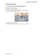
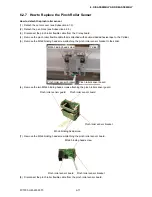
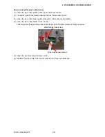
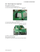
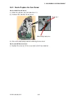
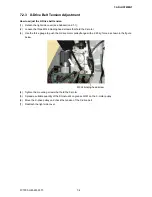
6.2.8 How to Replace the Y-relay Board
How to detach the Y-relay board
(1) Detach the center cover (see Subsection 6.1.3).
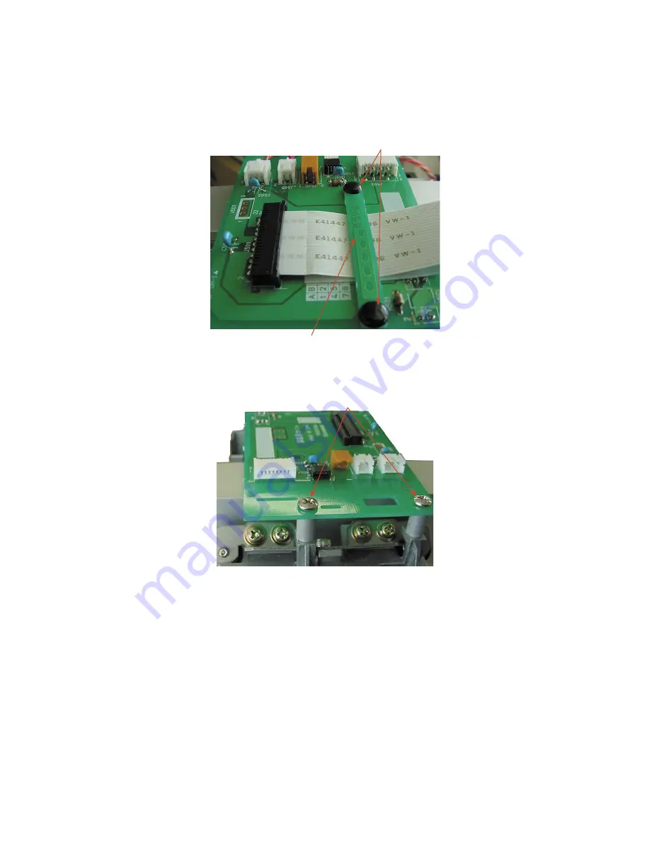
(2) Remove the two plastic rivets attaching the fl exible cable holding plate.
Plastic rivet
Flexible cable holding plate
(3) Disconnect all the cables from the Y-relay board.
(4) Remove the two M3L35 binding head screws attaching the Y-relay board.
M3L35 binding head screw
(5) Detach the Y-relay board from the Y-slider.
How to reinstall the Y-relay board
(1) Reattach the Y-relay board in the reverse order in which it was detached.
Summary of Contents for FC7000-100
Page 2: ......
Page 8: ......
Page 34: ......
Page 38: ......
Page 100: ......
Page 110: ......
Page 112: ...FC7000 UM 251 9370 10 2 10 PARTS LIST 1 2 3 4 5 6 7 8 10 9 Control Panel Assy 11 12...
Page 114: ...FC7000 UM 251 9370 10 4 10 PARTS LIST Control Panel 5 4 3 6 9 8 7 1 1 2 3 5 10...
Page 126: ......
Page 141: ...FC7000 UM 251 9370 11 15 11 BLOCK DIAGRAMS AND CIRCUIT DIAGRAMS 11 3 2 Main Board CPU...
Page 142: ...FC7000 UM 251 9370 11 16 11 BLOCK DIAGRAMS AND CIRCUIT DIAGRAMS 11 3 3 Main Board FPGA...
Page 143: ...FC7000 UM 251 9370 11 17 11 BLOCK DIAGRAMS AND CIRCUIT DIAGRAMS 11 3 4 Main Board I F...
Page 144: ...FC7000 UM 251 9370 11 18 11 BLOCK DIAGRAMS AND CIRCUIT DIAGRAMS 11 3 5 Main Board Motor Drive...
Page 145: ...FC7000 UM 251 9370 11 19 11 BLOCK DIAGRAMS AND CIRCUIT DIAGRAMS 11 3 6 Main Board Memory...
Page 146: ...FC7000 UM 251 9370 11 20 11 BLOCK DIAGRAMS AND CIRCUIT DIAGRAMS 11 3 7 Main Board Power Supply...

