FC7000-UM-251-9370
3-1
3. OPERATIONS
3. OPERATIONS
3.1 Control Panel
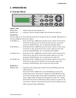
Indicator Lamps
POWER lamp: ................ Remains lit (green) while the plotter is on.
PROMPT lamp: .............. Lights green when the cutting data goes beyond the effective cutting area.
Function Keys
These four keys [F1, F2, F3 and F4] have functions which change as each menu changes. Depending on the
menu being displayed, these keys are used to:
F1 (FORCE) key: ............ When the FC7000 is in MENU mode, press the F1 key to select a function. When
the FC7000 is online, press F1 to select the Condition numbers 1 and 5. After
pressing the CONDITIONS key, use F1 to adjust the cutting/pen FORCE.
F2 (SPEED) key: ............ When the FC7000 is in MENU mode, press the F2 key to select a function. When
the FC7000 is online, press F2 to select the Condition numbers 2 and 6. After
pressing the CONDITIONS key, use F2 to adjust the cutting SPEED.
F3 (QUALITY) key: ......... When the FC7000 is in MENU mode, press the F3 key to select a function. When
the FC7000 is online, press F3 to select the Condition numbers 3 and 7. After
pressing the CONDITIONS key, use F3 to adjust the cutting QUALITY.
F4 (OFFSET) key: .......... When the FC7000 is in MENU mode, press the F4 key to select a function. When
the FC7000 is online, press F4 select the Condition numbers 4 and 8. After
pressing the CONDITIONS key, use F4 to adjust the cutting OFFSET.
Position Keys
POSITION keys .............. Depending on the operating status of the FC7000, the POSITION keys have the
following functions.
When the FC7000 is in MENU mode, use the POSITION keys to change the
setting values shown in the various menu displays. The POSITION keys are also
used to move the pen carriage and the media. If a POSITION key is pressed once,
the pen carriage moves the length of the step specified in Section 5.9, “Using the
MOVE STEP Function of the FC7000 User’s Manual”. If the key is held down, the
movement is continuous. To speed up the movement of the pen carriage, press the
NEXT key together with a POSITION key.
Summary of Contents for FC7000-100
Page 2: ......
Page 8: ......
Page 34: ......
Page 38: ......
Page 100: ......
Page 110: ......
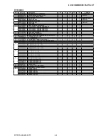
Page 112: ...FC7000 UM 251 9370 10 2 10 PARTS LIST 1 2 3 4 5 6 7 8 10 9 Control Panel Assy 11 12...
Page 114: ...FC7000 UM 251 9370 10 4 10 PARTS LIST Control Panel 5 4 3 6 9 8 7 1 1 2 3 5 10...
Page 126: ......
Page 141: ...FC7000 UM 251 9370 11 15 11 BLOCK DIAGRAMS AND CIRCUIT DIAGRAMS 11 3 2 Main Board CPU...
Page 142: ...FC7000 UM 251 9370 11 16 11 BLOCK DIAGRAMS AND CIRCUIT DIAGRAMS 11 3 3 Main Board FPGA...
Page 143: ...FC7000 UM 251 9370 11 17 11 BLOCK DIAGRAMS AND CIRCUIT DIAGRAMS 11 3 4 Main Board I F...
Page 144: ...FC7000 UM 251 9370 11 18 11 BLOCK DIAGRAMS AND CIRCUIT DIAGRAMS 11 3 5 Main Board Motor Drive...
Page 145: ...FC7000 UM 251 9370 11 19 11 BLOCK DIAGRAMS AND CIRCUIT DIAGRAMS 11 3 6 Main Board Memory...
Page 146: ...FC7000 UM 251 9370 11 20 11 BLOCK DIAGRAMS AND CIRCUIT DIAGRAMS 11 3 7 Main Board Power Supply...

