FC7000-UM-251-9370
3-2
3. OPERATIONS
Menu Keys
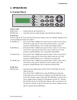
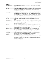
CONDITIONS key: ......... Press CONDITIONS to change the pen conditions shown on the FC7000 display
panel.
HOLD key: ...................... Press HOLD to temporarily suspend cutting or plotting. While the cutting or plotting
operation is suspended, the media set lever can be lowered to enable skewed
media to be reset if necessary.
MENU key: ..................... Press MENU to access the MENU mode. When this key is pressed, the MENU
mode is accessed and the green LED lights. Press it again to cancel MENU mode.
The green LED goes out. Use this key to set the various menu functions. If data is
received after the MENU key has been pressed, that data is temporarily stored in
the plotter’s buffer.
COPY key: ...................... Press COPY to repeat the cutting operation defined by the data in the plotter’s
buffer.
HOME/VIEW key: ........... Press HOME/VIEW to move the pen carriage to the standby position. Press it again
to move the pen carriage to the origin point. Press it one more time to return the
pen carriage to its former position.
NEXT key: ...................... When the FC7000 is in MENU mode, press NEXT to move to the next menu page.
TEST key: ....................... Press TEST to run a cutting test to check whether the currently-selected cutting
conditions are compatible with the media loaded.
AXIS/R.M.S. key: ............ Press AXIS/R.M.S. to initiate automatic reading of the registration marks. If Off
has been selected for the registration mark mode, this key is used to perform axis
alignment.
ORIGIN key: ................... Press ORIGIN to move the origin point. To reset the FC7000, press ORIGIN and
ENTER together when the initial MENU mode screen is displayed.
ENTER key: .................... Press ENTER to register your setting after setting a function.
To reset the FC7000, press ENTER and ORIGIN together when the INITIAL MENU
mode screen is displayed. The cutting area can also be displayed by pressing the
ENTER key in Ready status.
Summary of Contents for FC7000-100
Page 2: ......
Page 8: ......
Page 34: ......
Page 38: ......
Page 100: ......
Page 110: ......
Page 112: ...FC7000 UM 251 9370 10 2 10 PARTS LIST 1 2 3 4 5 6 7 8 10 9 Control Panel Assy 11 12...
Page 114: ...FC7000 UM 251 9370 10 4 10 PARTS LIST Control Panel 5 4 3 6 9 8 7 1 1 2 3 5 10...
Page 126: ......
Page 141: ...FC7000 UM 251 9370 11 15 11 BLOCK DIAGRAMS AND CIRCUIT DIAGRAMS 11 3 2 Main Board CPU...
Page 142: ...FC7000 UM 251 9370 11 16 11 BLOCK DIAGRAMS AND CIRCUIT DIAGRAMS 11 3 3 Main Board FPGA...
Page 143: ...FC7000 UM 251 9370 11 17 11 BLOCK DIAGRAMS AND CIRCUIT DIAGRAMS 11 3 4 Main Board I F...
Page 144: ...FC7000 UM 251 9370 11 18 11 BLOCK DIAGRAMS AND CIRCUIT DIAGRAMS 11 3 5 Main Board Motor Drive...
Page 145: ...FC7000 UM 251 9370 11 19 11 BLOCK DIAGRAMS AND CIRCUIT DIAGRAMS 11 3 6 Main Board Memory...
Page 146: ...FC7000 UM 251 9370 11 20 11 BLOCK DIAGRAMS AND CIRCUIT DIAGRAMS 11 3 7 Main Board Power Supply...


