


FC7000-UM-251-9370
9-7
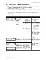
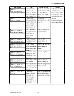
9. TROUBLESHOOTING
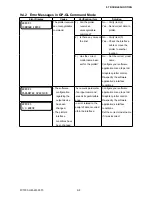
Error Display
Cause
Verification item
Solution
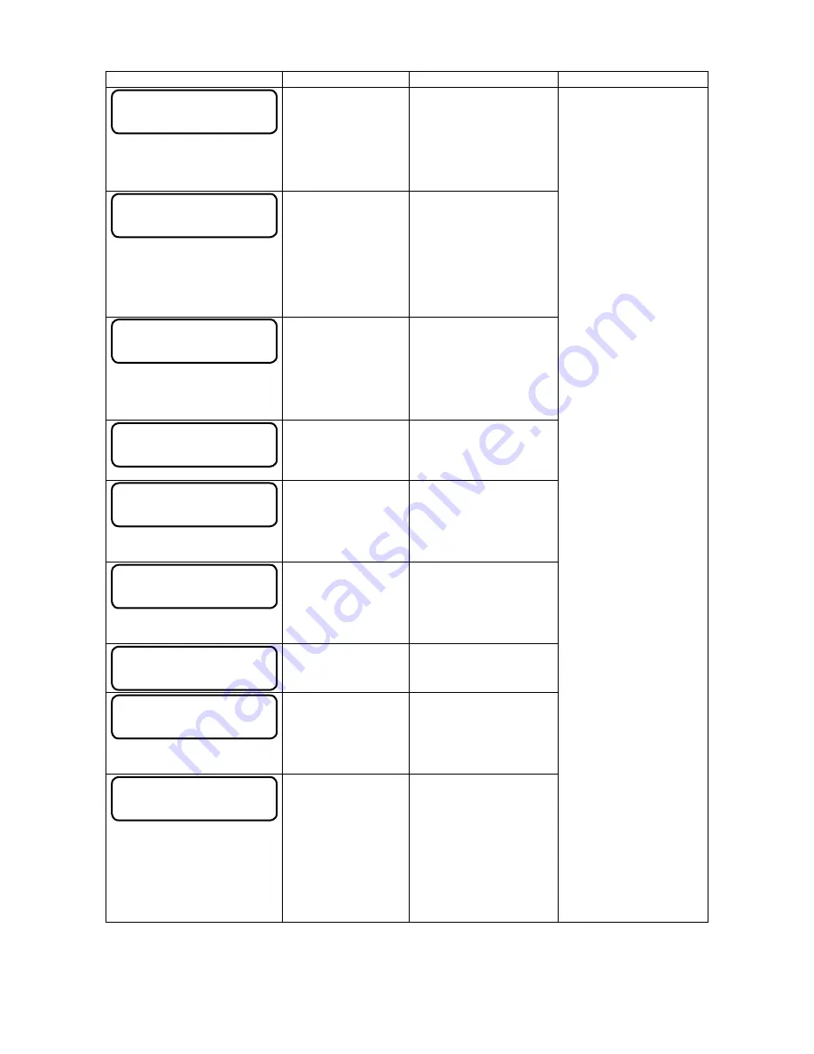
ERROR 6
Position overflow
A command was
executed with
coordinate data that
exceeds the effective
cutting/plotting area.
Execute the command
with its coordinate data
specified within the
effective cutting/plotting
area.
Configure your software
application menu to permit
Graphtec plotter control.
Re-specify the software
application’s interface
conditions.
Set the correct model
name if it was incorrect.
ERROR 7
Buffer overflow
The data being
input exceeded the
capacity of the plotter’
s downloadable
character buffer,
polygon buffer, etc.
Decrease the
downloadable characters,
polygons.
ERROR 10 Invalid
I/O output request
During execution of
an output command,
another output
command was
executed.
Check the flow of your
programmed data.
ERROR 11 Invalid
byte following ESC
The ESC character
was followed by an
invalid byte.
Check the ESC
commands in your
program.
ERROR 12 Invalid
byte I/O Control
A device control
command containing
an invalid byte was
received.
Check the device control
commands in your
program.
ERROR 13 Out of
range I/O parameter
A parameter outside
of the permissible
numeric range was
specified.
Check the program.
ERROR 14 Too many
I/O parameters
Too many parameters
were received.
Check the number of
command parameters.
ERROR 15 Error in
I/O transmission
During data transfer,
a framing error, parity
error, or overrun error
occurred.
Check the settings of the
interface conditions.
ERROR 16 I/O buffer
overflow
The I/O buffer
received data at a
faster pace than
it could process,
indicating that
handshaking is not
successful.
Check the settings of the
handshaking mode and
other interface conditions.
Summary of Contents for FC7000-100
Page 2: ......
Page 8: ......
Page 34: ......
Page 38: ......
Page 100: ......
Page 110: ......
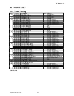
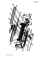
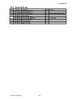
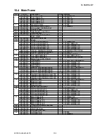
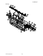
Page 112: ...FC7000 UM 251 9370 10 2 10 PARTS LIST 1 2 3 4 5 6 7 8 10 9 Control Panel Assy 11 12...
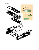
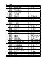
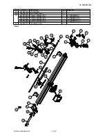
Page 114: ...FC7000 UM 251 9370 10 4 10 PARTS LIST Control Panel 5 4 3 6 9 8 7 1 1 2 3 5 10...
Page 126: ......
Page 141: ...FC7000 UM 251 9370 11 15 11 BLOCK DIAGRAMS AND CIRCUIT DIAGRAMS 11 3 2 Main Board CPU...
Page 142: ...FC7000 UM 251 9370 11 16 11 BLOCK DIAGRAMS AND CIRCUIT DIAGRAMS 11 3 3 Main Board FPGA...
Page 143: ...FC7000 UM 251 9370 11 17 11 BLOCK DIAGRAMS AND CIRCUIT DIAGRAMS 11 3 4 Main Board I F...
Page 144: ...FC7000 UM 251 9370 11 18 11 BLOCK DIAGRAMS AND CIRCUIT DIAGRAMS 11 3 5 Main Board Motor Drive...
Page 145: ...FC7000 UM 251 9370 11 19 11 BLOCK DIAGRAMS AND CIRCUIT DIAGRAMS 11 3 6 Main Board Memory...
Page 146: ...FC7000 UM 251 9370 11 20 11 BLOCK DIAGRAMS AND CIRCUIT DIAGRAMS 11 3 7 Main Board Power Supply...