

FC7000-UM-251-9370
9-2
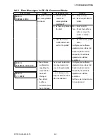
9. TROUBLESHOOTING
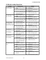
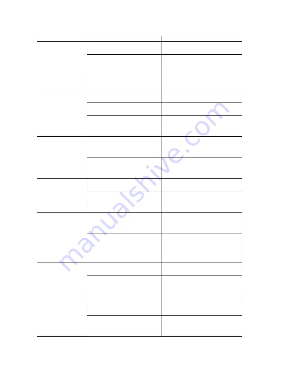
9.2 Media Loading Operations
Symptom
Verification item
Solution
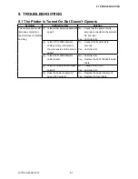
The media drops to the
front of the plotter.
(1) Is the front edge of the media
curled?
Yes ....Replace the media.
No .....Verify item (2).
(2) Is the front media sensor dirty? Yes ....Clean the front media sensor.
No .....Verify item (3).
(3) Is the front media sensor cable
securely connected to the main
board and the sensor?
Yes ....Replace the front media sensor.
No .....Connect the cable securely.
The media drops to the
rear of the plotter.
(1) Is the rear edge of the media
curled?
Yes ....Replace the media.
No .....Verify item (2).
(2) Is the rear media sensor dirty?
Yes ....Clean the rear media sensor.
No .....Verify item (3).
(3) Is the rear media sensor cable
securely connected to the main
board and the sensor?
Yes ....Replace the rear media sensor.
No .....Connect the cable securely.
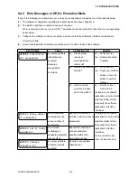
The plotter displays
“LOAD MEDIA!” when
media has been loaded.
(1) Does the cam sensor plate
block the cam sensor?
Yes ....Check the cam sensor plate and
attach it at the correct position.
No .....Verify item (2).
(2) Is the cam sensor cable
securely connected to the main
board and the sensor?
No .....Connect the cable securely.
Yes ....Replace the cam sensor board.
The plotter can’t
recognize the Y direction
of the media size.
(1) Is there any dust on the pinch
roller sensor?
Yes ....Clean the pinch roller sensor.
No .....Verify item (2).
(2) Is the pinch roller sensor flexible
cable securely connected to
each connector?
Yes ....Replace the pinch roller sensor.
No .....Connect the cable securely.
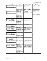
The plotter can’t
recognize the X direction
of the media size.
(1) Is there any dust on the front
media sensor and the rear
media sensor?
Yes ....Clean the front media sensor and
the rear media sensor.
No .....Verify item (2).
(2) Are the front media sensor and
the rear media sensor cables
securely connected to each
connector?
No .....Connect the cables securely.
Yes ....Replace the sensor(s).
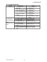
The media is fed at an
angle.
(1) Are the pinch rollers worn
down?
Yes ....Replace the pinch roller(s).
No .....Verify item (2).
(2) Is there anything on the drive
roller?
Yes ....Clean the drive roller with a brush.
No .....Verify item (3).
(3) Do the pinch rollers have the
correct pressure?
No .....Replace the pinch roller spring(s).
Yes ....Verify item (4).
(4) Is the drive roller worn down?
Yes ....Replace the drive roller.
No .....Verify item (5).
(5) Is the drive roller attached
correctly?
Yes ....Replace the bearing of the drive
roller.
No .....Attach the drive roller correctly.
Summary of Contents for FC7000-100
Page 2: ......
Page 8: ......
Page 34: ......
Page 38: ......
Page 100: ......
Page 110: ......
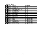
Page 112: ...FC7000 UM 251 9370 10 2 10 PARTS LIST 1 2 3 4 5 6 7 8 10 9 Control Panel Assy 11 12...
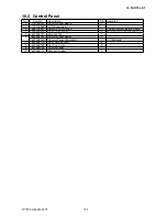
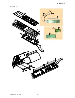
Page 114: ...FC7000 UM 251 9370 10 4 10 PARTS LIST Control Panel 5 4 3 6 9 8 7 1 1 2 3 5 10...
Page 126: ......
Page 141: ...FC7000 UM 251 9370 11 15 11 BLOCK DIAGRAMS AND CIRCUIT DIAGRAMS 11 3 2 Main Board CPU...
Page 142: ...FC7000 UM 251 9370 11 16 11 BLOCK DIAGRAMS AND CIRCUIT DIAGRAMS 11 3 3 Main Board FPGA...
Page 143: ...FC7000 UM 251 9370 11 17 11 BLOCK DIAGRAMS AND CIRCUIT DIAGRAMS 11 3 4 Main Board I F...
Page 144: ...FC7000 UM 251 9370 11 18 11 BLOCK DIAGRAMS AND CIRCUIT DIAGRAMS 11 3 5 Main Board Motor Drive...
Page 145: ...FC7000 UM 251 9370 11 19 11 BLOCK DIAGRAMS AND CIRCUIT DIAGRAMS 11 3 6 Main Board Memory...
Page 146: ...FC7000 UM 251 9370 11 20 11 BLOCK DIAGRAMS AND CIRCUIT DIAGRAMS 11 3 7 Main Board Power Supply...