FC7000-UM-251-9370
2-1
2. PARTS NAMES and FUNCTIONS
2. PARTS NAMES and FUNCTIONS
2.1 Parts Names and Functions
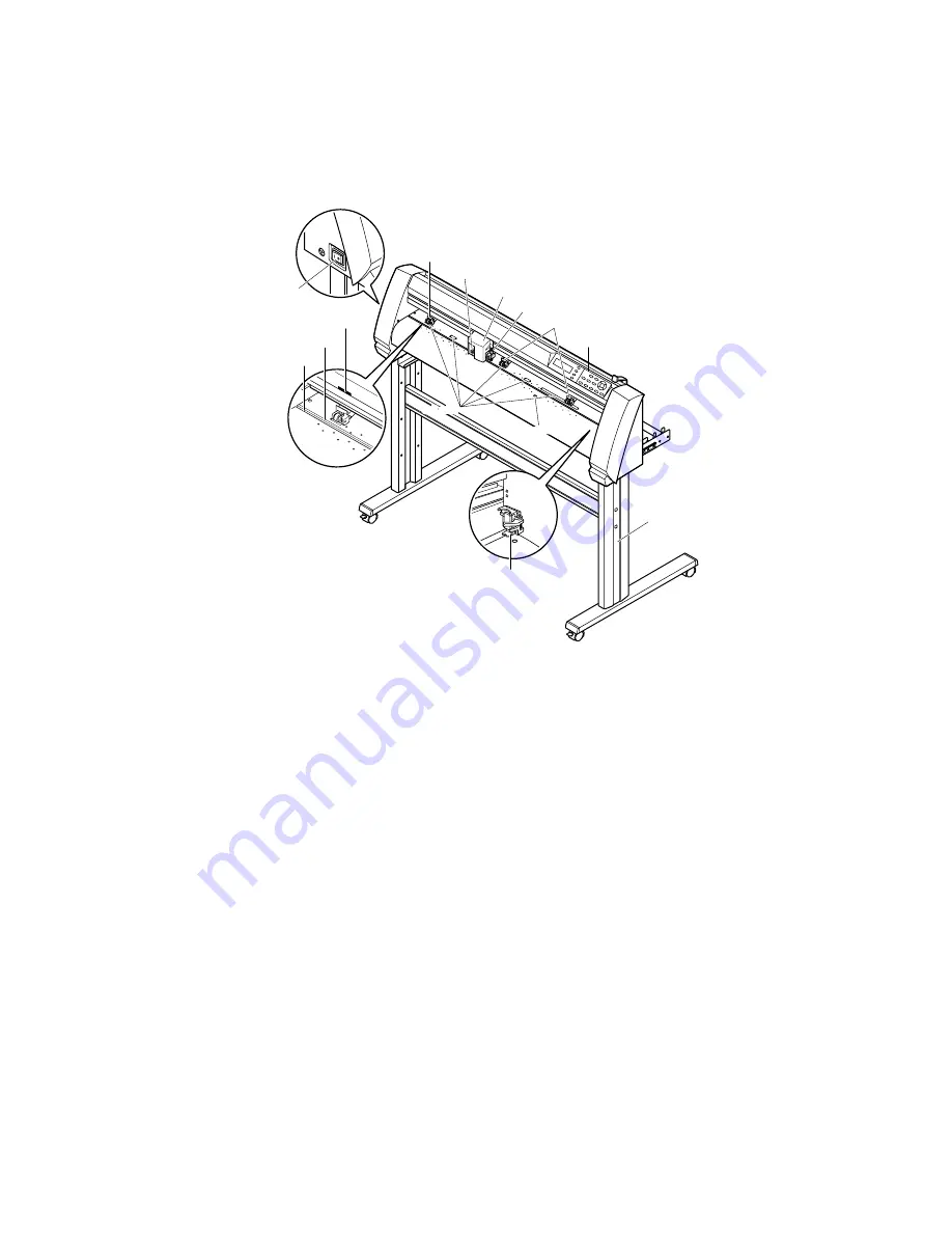
Front View
Grit roller
Media sensor
Power switch
Pinch roller
Pen carriage
Cross-cutter unit
Pen holder
Pinch rollers
Control panel
Stand
Cutting groove
Cutting mat
Grit roller position guide
Pen station
Grit roller
Media sensor
Power switch: ................. Used to turn the plotter on and off.
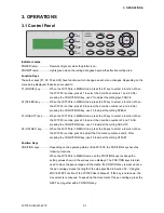
Control panel: ................. Used to access various plotter functions.
Pinch rollers: ................... Rollers that push the media against the grit rollers.
Grit rollers: ...................... Metallic rollers with a file-like surface that feed the media back and forth.
Media sensors: ............... The front sensor is used to sense the leading edge of the media. The rear sensor is
used to sense the trailing edge of the media.
Pen carriage: .................. Moves the cutter-pen or plotting pen across the media during cutting or plotting.
Pen holder: ..................... Holds the cutter-pen or plotting pen and moves it up or down.
Pen station (installed on 2-pen models only):
The second pen is mounted here.
Stand: ............................. Used to make the plotter more portable and to free up counter space.
Grit roller position guide:
Stickers on the front of the Y rail and the rear side of the top cover that show the
position of each grit roller. Use these alignment marks as an aid in locating the
pinch rollers.
Cutting groove: ............... Used when cross-cutting is performed.
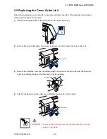
Cross-cutter unit: ............ Used to perform cross-cutting of media so that the cut length can be removed from
the roll.
Summary of Contents for FC7000-100
Page 2: ......
Page 8: ......
Page 34: ......
Page 38: ......
Page 100: ......
Page 110: ......
Page 112: ...FC7000 UM 251 9370 10 2 10 PARTS LIST 1 2 3 4 5 6 7 8 10 9 Control Panel Assy 11 12...
Page 114: ...FC7000 UM 251 9370 10 4 10 PARTS LIST Control Panel 5 4 3 6 9 8 7 1 1 2 3 5 10...
Page 126: ......
Page 141: ...FC7000 UM 251 9370 11 15 11 BLOCK DIAGRAMS AND CIRCUIT DIAGRAMS 11 3 2 Main Board CPU...
Page 142: ...FC7000 UM 251 9370 11 16 11 BLOCK DIAGRAMS AND CIRCUIT DIAGRAMS 11 3 3 Main Board FPGA...
Page 143: ...FC7000 UM 251 9370 11 17 11 BLOCK DIAGRAMS AND CIRCUIT DIAGRAMS 11 3 4 Main Board I F...
Page 144: ...FC7000 UM 251 9370 11 18 11 BLOCK DIAGRAMS AND CIRCUIT DIAGRAMS 11 3 5 Main Board Motor Drive...
Page 145: ...FC7000 UM 251 9370 11 19 11 BLOCK DIAGRAMS AND CIRCUIT DIAGRAMS 11 3 6 Main Board Memory...
Page 146: ...FC7000 UM 251 9370 11 20 11 BLOCK DIAGRAMS AND CIRCUIT DIAGRAMS 11 3 7 Main Board Power Supply...


