background image

- 24 -

12. How to install the iMark Plus software

Please check the following items before installing the iMark Plus software into the computer.

When there is virus detection programs and programs that reside in the system,

please exit in advance.

To install the software, login the Windows as a member of the administrator account

that has administrator rights on the computer.

The procedure to installing the iMark Plus software into the Windows 7 (32bit) environment
is described.

1. Insert the iMark Plus software CD into the CD drive of the computer,

and then AutoPlay will be displayed. Click the “Open folder to view files”.

AutoPlay

DVD RW Drive

General Options

View more AutoPlay options in Control Panel

Open folder to view files

using Windows Explorer

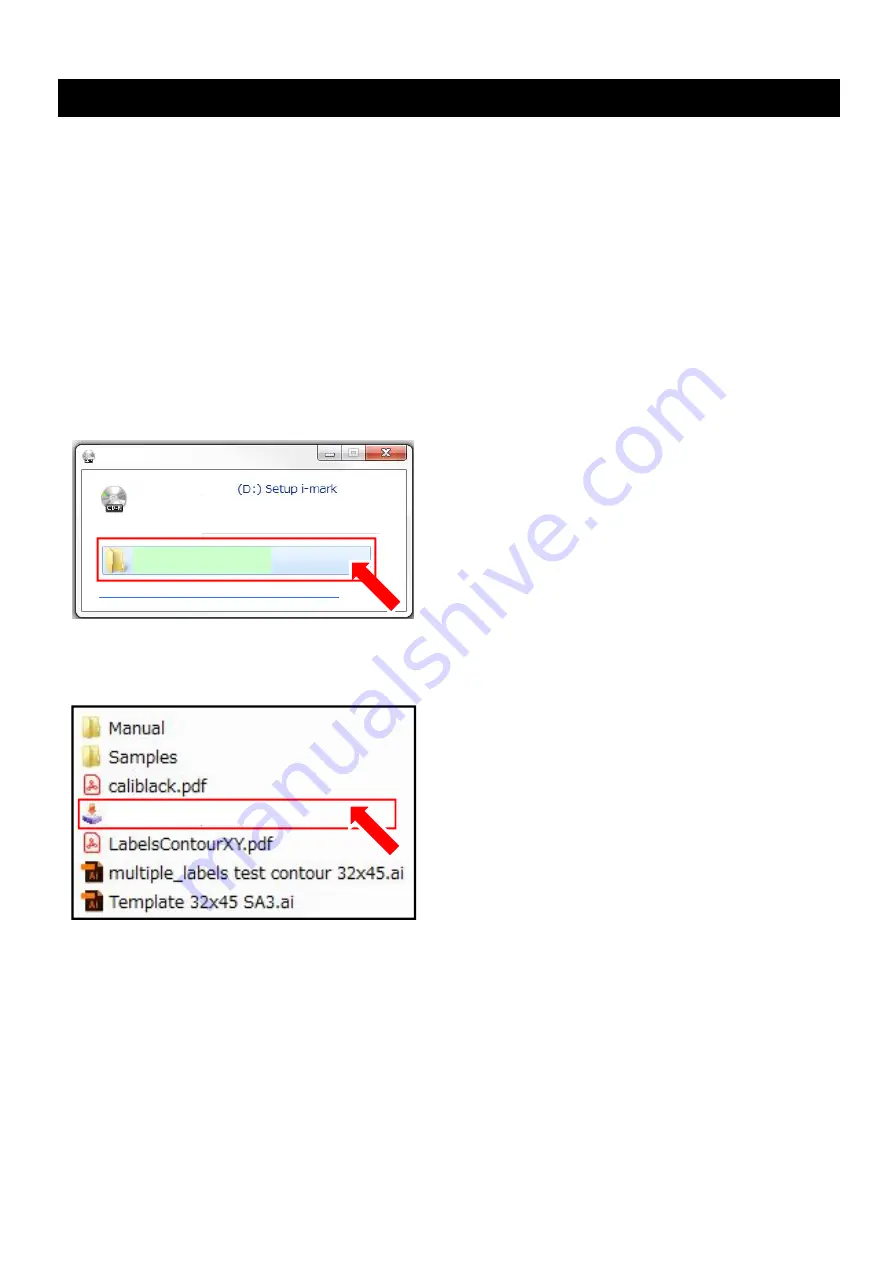
2. The files in the CD will be displayed.

Select the “iMarkPlusSetup.exe”, and double click it.

i

MarkPlusSetup.exe

Summary of Contents for F-Mark 2

Page 1: ...Setup user s manual F Mark2 setup user s manual_01E Read this manual carefully before using the machine Keep the manual in a handy place for future reference 2...

Page 2: ...0 20 11 Cable connection 23 12 How to install the iMark Plus software 24 13 Notice on using the iMark Plus software 28 14 How to adjust the angle of the Camera 30 15 How to initialize F Mark2 and CE70...

Page 3: ...ation or anything unusual while using it Indicates a potentially hazardous situation which if not avoided could result in minor or moderate injury Follow these guidelines to avid the risk of injury el...

Page 4: ...s spotlight it may not operate properly Media restrictions to be used with the F Mark2 Curled media cannot be use with the F Mark2 Thick media may not be use with the F Mark2 because it interferes wit...

Page 5: ...ce of F Mark2 The required space is 800 mm or more in width 820 mm or more in length 420 mm or more in height Because the Exit tray hangs 420mm from the top of work table Please prepare the tree place...

Page 6: ...ng Guaranteed accuracy environment 16 to 32 35 to 70 R H non condensing Installation space L x W Tabletop 820x750mm 4 Main Specifications The F Mark2 automatic feeder is part of the CE7000 ASF Auto Sh...

Page 7: ...to the CE7000 40 50 mm space is required on each side of the CE7000 40 to connect the power cord and USB cable to the CE7000 40 When installing F Mark2 and CE7000 40 the Exit Tray expands 380 mm from...

Page 8: ...6 6 How to unpack the box of F Mark2 1 Open the box of the F Mark2 with a knife 2 Remove the packing material from the box 3 Take out the Accessories box from the box...

Page 9: ...7 4 Take out the Exit tray from the box 5 Remove the packing material from the box 6 Remove the side packing materials from the box...

Page 10: ...8 7 Remove the back side packing material from the box 8 Take out the F Mark2 from the box 9 Take out the F Mark2 from the packing plastic bag...

Page 11: ...9 10 Peel off two Velcro which fixing the Arm cushioning material 12 Detach the rear Arm cushioning material from the F Mark2 11 Detach the front Arm cushioning material from the F Mark2...

Page 12: ...10 13 Detach the two cushioning materials under the Arm from the F Mark2 14 Turn the Blower to the side 15 Take out the Exit Tray from the packing plastic bag...

Page 13: ...11 16 Take out the Test Cut sheets and Calibration sheets from the Exit Tray There are 12 Test Cut sheets and 2 Calibration sheets...

Page 14: ...ing 1 Suction cup for spare 2 AC power adapter for F Mark 1 Power cord for AC power adapter The plug shape varies depending on the region 1 1 Open the accessories box with a knife 7 Confirm the access...

Page 15: ...1 0m from USB Hub to Cutting plotter 1 Adhesive cable crip for camera cable fixing 2 Alignment label For mounting position of F Mark2 to CE7000 40 2 CD Rom 1 Safety Precautions 1 Calibration sheet Not...

Page 16: ...14 Item Image Quantity Stopper Plate Not in the accessories box 1 Tail Tool Not in the accessories box 1 Exit Tray Not in the accessories box 1...

Page 17: ...a Guide Adjust the width of Side Media Guide depending on the media width Adjusting Knob to be used When adjusting it make suer that Side Media Guide lightly touches to side of media If width of Side...

Page 18: ...hen inserting the media to the cutting plotter Vacuum Adjusting Kob Adjust the vacuum force to pick up media When turning the knob clockwise the vacuum force increasing When turning the knob countercl...

Page 19: ...y firmly on the Working table The adhesive tape fix the Exit tray for a short time it may drop if you do not place the CE7000 40 3 Put the CE7000 40 on top of the Exit tray There are two ribs on the f...

Page 20: ...lign the 9th line of the Rear Cover of the CE7000 40 in order to media which after cut by the CE7000 40 drop into the Exit tray correctly 5 Align the center of Alignment label with the 7th line of the...

Page 21: ...19 6 Connect the F Mark2 to the CE7000 40 so that the front edge of the F Mark2 fits into the groove on the Front Cover of the CE7000 40...

Page 22: ...e accessory allen wrench 2 Separate the Bracket from the Camera 3 Insert the Bracket into the back of Center Cover of the CE7000 40 4 Attach the Bracket to the left side of the Center Cover of the CE7...

Page 23: ...to the Bracket to fixing the Camera to the Center Cover of the CE7000 40 When attaching the two screws to the Bracket align the screw holes on the Bracket with holes on on the Camera Stay Screw hole...

Page 24: ...ing the accessory allen wrench to fix the Camera to the CE7000 40 8 Detach the Camera Lens Cover from the Camera 9 Paste the two Adhesive cable crips to the left side inner wall of the CE7000 40 And t...

Page 25: ...m the inside of the F Mark2 USB cable to the camera AC power cable to the AC power adapter USB cable to the CE7000 NOTICE After cables connection confirm that there is no add load to the cables Please...

Page 26: ...t has administrator rights on the computer The procedure to installing the iMark Plus software into the Windows 7 32bit environment is described 1 Insert the iMark Plus software CD into the CD drive o...

Page 27: ...y to install the iMark Plus software will be displayed Click the Next button NOTICE Do not change the folder that installing the iMark Plus software from the default settings C Script 4 The window for...

Page 28: ...rted 7 When iMark Plus software installation is completed the Microsoft Visual C 2012 installing window will be displayed 8 Click the check box of I agree to the license terms and conditions and then...

Page 29: ...ill be started 10 When installation is completed click the Close button to close the window 11 Click the Exit button to complete the installation NOTICE iMark Puls software will not be launch if the F...

Page 30: ...n computer of iMark Plus software If operating the iMark Plus software on a computer with internal camera the iMark software can not be launched because the internal camera is detected as camera of F...

Page 31: ...k Plus software can not be launched because the F Mark2 camera can not be used In that case please change the setting of camera privacy in the following procedure Procedure to change the setting of ca...

Page 32: ...mb screws on right side of the Camera to adjust the angle of the Camera 3 Adjust the angle of the Camera so that the groove on the Front Cover of the CE7000 align to the reference lines that displayed...

Page 33: ...the Camera does not change NOTICE After adjusting the angle of Camera please operate the F Mark2 so that the angle of Camera does not change Before cutting media with F Mark2 or performing the Calibr...

Page 34: ...picture below NOTICE This position is reference position of the left side Push Roller Do not move the position of left side Push Roller from the reference position if move it the F Mark2 will not oper...

Page 35: ...ting of the CE7000 40 Displayed unit of the CE7000 40 and operating units of iMark Plus software are not linked 4 Lower the Media Set Lever of the CE7000 40 and loading the media into the CE7000 40 NO...

Page 36: ...l of the CE7000 40 Then the Tool Carriage will be moved between the left and right Push Rollers After that the READY will be displayed on the control panel of the CE7000 40 After Tool Carriage moving...

Page 37: ...rk icon on the upper left in the iMark Plus software screen 7 Pull down menu will be displayed and then click the About iMark to open the About iMark window Restore Size Maximize Move Minimize Close 8...

Page 38: ...e control panel Label Media 10 Click the Close button to finish the setting of CE7000 40 NOTICE This procedure needs to be performed under the following conditions in order to operate the F Mark2 prop...

Page 39: ...has been changed to the F Mark2 The angle of camera has been adjusted correctly The left side Push Roller of the CE7000 40 is in the correct position 1 Lower the Media Set Lever of the CE7000 40 and l...

Page 40: ...for Half Cutting Cutter Plunger NOTICE For the how to set the Cutter Plunger to the Tool Holder on the CE7000 40 please refer to the User s manual of the CE7000 40 For the how to adjust the blade len...

Page 41: ...checked and then click the Calibration button NOTICE Calibration can not be performed correctly if Enable in the Dashed line is checked 4 The Calibration window will be displayed then click the Cut Ma...

Page 42: ...can not be peeled off well from the Calibration Sheet or if the cut square cut out from the Calibration Sheet please adjust the following items Adjust Cut force in the iMark Plus software Adjust the...

Page 43: ...ase please shade the camera unit so that the small square part is not reflected by the light and then perform the Read Maker After performed Calibration When correct calibration is performed the value...

Page 44: ...s are included in the F Mark2 if used up these please print the caliblack pdf image data which is installed to the accessory CD to the label media and use it as a calibration sheet The calibration dat...

Page 45: ...CE7000 40 The settings of CE7000 40 has been changed to the F Mark2 The angle of camera has been adjusted correctly The left side Push Roller of the CE7000 40 is in the correct position Calibration o...

Page 46: ...40 And then shift the position of the F Mark2 so that the crop mark on the Test Cut sheet under the Camera 3 Launch the iMark Plus software and then fine adjust the position of the F Mark2 so that the...

Page 47: ...ing to the width of Test Cut sheet NOTICE Never move the left side Push Roller position 5 Remove the Test Cut sheet from the CE7000 40 6 Rise the Media Set Lever of the CE7000 40 and then press the 2...

Page 48: ...k Plus software The cut data file multiple_labels test contour 32x45 ai for the Test Cut sheet is included in the F Mark2 accessory CD Please copy this file into the operation computer if necessary 8...

Page 49: ...47 9 Make sure that the Cutter ready is displayed on the bottom of the iMark Plus software window and then click the Cut Test button to perform the cut test to the Test Cut sheet...

Page 50: ...in X the cutting position can be shift to the horizontal direction of the media Adjustment of cutting position in Y direction Adjustment of cutting position in Y direction can be adjusting by inputtin...

Page 51: ...be effective for the cutting position without perform the cut by click the Cut Test button Therefore after inputting the values for X and Y make sure to click the Cut Test button to perform the cut T...

Page 52: ...on of Side Media Guide adjust the position so that the Side Media Guide lightly touches to the side of media to be used 3 Adjust the position of Rear Media Guide depending on the length of media to be...

Page 53: ...he front edge of media into the Media Supply Tray 4 When using Blowers adjust the rotation speed of Blowers and the width of Side Media Guide So that the media slightly rises Blowers Speed Adjusting K...

Page 54: ...ching the Stopper Plate on the Exit Tray Stopper Plate can be attach any position on the Exit Tray because back of Stopper Plate is magnetized Attaching position of Stopper Plate When attach the Stopp...

Page 55: ...is attached to the rear part of CE7000 40 the media that after cutting with CE7000 40 will be fit into the Exit Tray without scattering Attach the Tail Tool to the rear part of the CE7000 40 as shown...

Page 56: ...OTICE The Extension Plate is not included in accessories of F Mark2 It si sold separately The Extension Plate can be attached to F Mark2 in the following procedure 1 Remove the two M4L10 allen screws...

Page 57: ...55 4 Attach the Extension Plate to F Mark2 3 Fix the Extension Plate to F Mark2 with two M4L10 allen screws using the 2 5mm allen wrench Extension Plate M4L10 allen screw Extension Plate...

Page 58: ...ia pick up Insertion Flap The Insertion Flap help keep the media flat while inserting media into the CE7000 40 Replace the Insertion Flap if it is damaged NOTICE Two Suction Cups are included in the a...

Page 59: ...ection part where located on the front edge of the Arm and then insert the Suction Cups When inserting the Suction Cups insert the Suction Cups while rotating it so that the Suction Cups are firmly in...

Page 60: ...maged If power cord is damaged immediately stop using power cord and replace it Check that the connection of the AC power adapter connected correctly If green light on the AC power adapter does not on...

Page 61: ...he each USB cable and USB Hub connectors are not damaged If it is damaged immediately stop using damaged item and replace it Put the hands under the camera and check that the hands displayed in the pr...

Page 62: ...ack The USB cable of the camera is not connected securely to the USB Hub Check that the USB cable of camera is connected correctly The cap of lens is not removed from the camera Remove the cap of lend...

Page 63: ...ng the iMark Plus software The camera privacy setting on the operation computer is set to OFF Set the camera privacy setting of the operation computer is set to ON Refer to Notice on using the iMark P...

Page 64: ...d with the camera due to connection positon between F Mark2 and CE7000 40 is incorrect Adjust the position of F Mark2 so that the crop mark will be displayed on the center of preview window in the iMa...

Page 65: ...reflected to the cutting The Cut Test in the iMark Plus software has not been performed after inputting the values or changing the settings After inputting the values or changing the settings in the...

Reviews: