CE7000-UM-251-9370 7-21
7 DISASSEMBLY AND REASSEMBLY
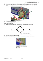
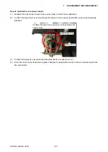
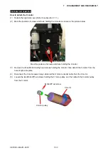
(8) Remove the four M3L6 binding head screws attaching the right and left Y-belt stopper plates to the
slider.
M3L6 binding head screw
Y belt
Stopper
(9) Detach the Y-belt from the unit.
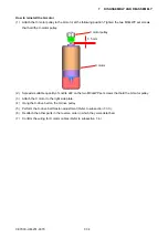
How to reinstall the Y-belt
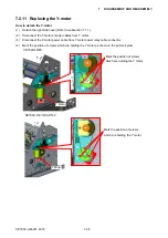
(1) Shave 2 to 3 mm off both ends of the Y-belt until the wire comes out as shown below.
Y-belt
Shave 2 to 3 mm off both ends of
the Y-belt until the wire comes out.
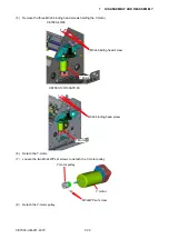
(2) Hang the Y-belt on both sides of the pulley.
(3)
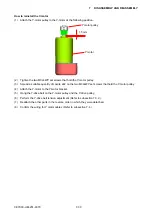
When the Y-belt is installing to the Y-slider, the four notches of the Y-belt fit into the Y-slider.
Four notches of the Y-belt fit into
the Y-slider.
Y belt
Summary of Contents for CE7000-130
Page 1: ...CE7000 UM 251 00 9370 CUTTING PLOTTER SERVICE MANUAL CE7000 40 60 130 160 130AP ...
Page 2: ......
Page 4: ...CE7000 UM 251 9370 II ...
Page 72: ...CE7000 UM 251 9370 5 2 5 RECOMMENDED PARTS LIST ...
Page 74: ......

