


CE7000-UM-251-9370 3-1
3 PARTS NAMES and FUNCTIONS
3 PARTS NAMES and FUNCTIONS
3.1 Parts Names and Functions
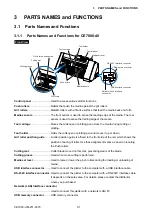
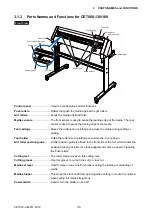
3.1.1 Parts Names and Functions for CE7000-40
Front View
Cutting mat
Grit roller position guide
Cutting groove
Tool carriage
Tool holder
Control panel
Media set lever
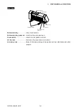
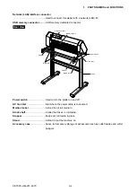
USB interface connector
USB memory connector
RS-232C interface connector
Push rollers
Media sensors
Grit rollers
Network (LAN) Interface
connector
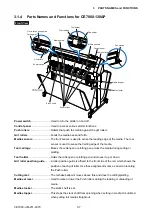
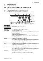
Control panel
���������������������������Used to access various plotter functions�
Push rollers
������������������������������Rollers that push the media against the grit rollers�
Grit rollers
��������������������������������Metallic rollers with a file-like surface that feed the media back and forth�
Media sensors
��������������������������The front sensor is used to sense the leading edge of the media� The rear
sensor is used to sense the trailing edge of the media�
Tool carriage
����������������������������Moves the cutter-pen or plotting pen across the media during cutting or
plotting�
Tool holder
�������������������������������Holds the cutter-pen or plotting pen and moves it up or down�
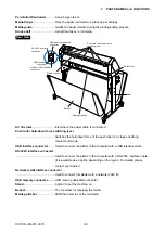
Grit roller position guide
���������A roller position guide is affixed to the front side of the rail, which shows the
position of each grit roller� Use these alignment marks as an aid in locating
the Push rollers�
Cutting mat
�������������������������������Cutter blade moved on this mat, preventing wears of the blade�
Cutting groove
�������������������������Used when cross-cutting is performed�
Media set lever
�������������������������Used to raise or lower the pinch rollers during the loading or unloading of
media�
USB interface connector
���������Used to connect the plotter to the computer with a USB interface cable�
RS-232C interface connector
�Used to connect the plotter to the computer with a RS-232C interface cable�
It depends on the sales area� For details, please contact the distributor
where you purchased�
Network (LAN) Interface connector
���������������������������������������������������Used to connect this plotter with a network (LAN) I/F�
USB memory connector
���������USB memory connector�
Summary of Contents for CE7000-130
Page 1: ...CE7000 UM 251 00 9370 CUTTING PLOTTER SERVICE MANUAL CE7000 40 60 130 160 130AP ...
Page 2: ......
Page 4: ...CE7000 UM 251 9370 II ...
Page 72: ...CE7000 UM 251 9370 5 2 5 RECOMMENDED PARTS LIST ...
Page 74: ......


