CE7000-UM-251-9370 IV
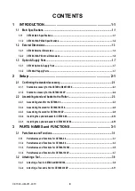
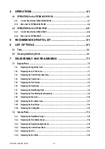
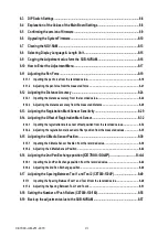
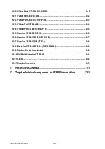
4 OPERATIONS ............................................................................ 4-1
4.1.1 Control Panel for the CE7000-40/60/130/160 ....................................................................................... 4-1
4.1.2 Menu tree for CE7000-40/60/130/160 ....................................................................................................4-6
4.2.1 Control Panel for the CE7000-130AP ..................................................................................................4-14
4.2.2 Menu tree for CE7000-130AP ...............................................................................................................4-18
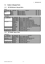
5 RECOMMENDED PARTS LIST ................................................. 5-1
6 LIST OF TOOLS ........................................................................ 6-1
7 DISASSEMBLY AND REASSEMBLY ........................................7-1
7.1.2 Replacing the Left Side Cover ...............................................................................................................7-1
7.1.3 Replacing the Control Panel Assembly ................................................................................................7-2
7.1.4 Replacing the Center Cover ...................................................................................................................7-3
7.1.5 Replacing the Front Guide .....................................................................................................................7-4
7.1.6 Replacing the Rear Guide ......................................................................................................................7-6
7.1.7 Replacing the Rear Writing Panel .........................................................................................................7-8
7.1.8 Replacing the Front Writing Panel Assembly ......................................................................................7-9
7.1.9 Replacing the Fan Cover ......................................................................................................................7-10
7.1.10 Replacing the Pen Block Cover ...........................................................................................................7-11
7.1.11 Replacing the Push Roller ...................................................................................................................7-12
7.1.12 Replacing the Cutting Mat ...................................................................................................................7-13
7.2.1 Replacing the Rear Media Sensor .......................................................................................................7-14
7.2.2 Replacing the Front Media Sensor ......................................................................................................7-14
7.2.3 Replacing the Registration Mark Sensor ............................................................................................7-15
7.2.4 Replacing the Control Panel Board.....................................................................................................7-16
7.2.5 Replacing the LCD ................................................................................................................................7-17
7.2.6 Replacing the Pen Block ......................................................................................................................7-18
Summary of Contents for CE7000-130
Page 1: ...CE7000 UM 251 00 9370 CUTTING PLOTTER SERVICE MANUAL CE7000 40 60 130 160 130AP ...
Page 2: ......
Page 4: ...CE7000 UM 251 9370 II ...
Page 72: ...CE7000 UM 251 9370 5 2 5 RECOMMENDED PARTS LIST ...
Page 74: ......


