


CE7000-UM-251-9370 7-56
7 DISASSEMBLY AND REASSEMBLY
CE7000-130//130AP/160
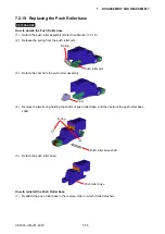
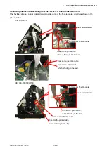
How to detach the Push Roller base
Don’t loosen any screws on the push roller assembly.
(1) Detach the push roller assembly (Refer to subsection 7.2.18.).
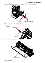
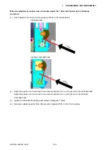
(2) Release the spring from the push roller arm.
Push roller arm
Spring
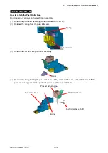
(3) Detach the cam from the push roller assembly.
Cam
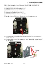
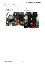
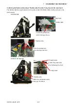
(4) Remove the E-ring holding the push roller base shaft, and then detach the push roller base shaft, the
presser adjusting part and the push roller lever from the push roller base.
E-ring
Push roller
base
Presser adjusting part
Push roller lever
Push roller
base shaft
Summary of Contents for CE7000-130
Page 1: ...CE7000 UM 251 00 9370 CUTTING PLOTTER SERVICE MANUAL CE7000 40 60 130 160 130AP ...
Page 2: ......
Page 4: ...CE7000 UM 251 9370 II ...
Page 72: ...CE7000 UM 251 9370 5 2 5 RECOMMENDED PARTS LIST ...
Page 74: ......


