CE7000-UM-251-9370 32
9 TROUBLESHOOTING
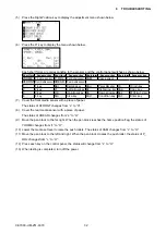
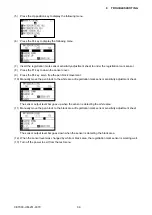
(5) Press the Right Position key to display the adjustment menu shown below.
(6) Press the F1 key to display the menu shown below.
Each short forms are corresponding to the sensors and the control panel switches as shown below.
Short form Sensor or key Short form Sensor or key Short form Sensor or key Short form Sensor or key
YHOME Y home sensor P_ROL Push roller sensor CAM
Cam sensor
XFRONT Front media sensor XREAR Rear media sensor
1
1 key
Bar
Barcode key
Pau
Pause Menu key Ori
Origin key
2
2 key
Lf
Left arrow key Ri
Right arrow key Cop
Copy key
3
3 key
Up
Up arrow key Dn
Down arrow key Esc
ESC/Cross Cut key
4
4 key
Slo
Slow key
Cod
Condition key Ent
Enter key
(7) Cover the front media sensor with a piece of paper.
The status of XFRONT changes from “L” to “H”.
(8) Cover the rear media sensor with a piece of paper.
The status of XREAR changes from “L” to “H”.
(9)
Move the pen block to the far right. When the pen block reaches the home position flag, the status of
YHOME changes from “L” to “H”.
(10) Lower the media set lever to raise the push rollers. The status of CAM changes from “L” to “H”.
(11) Move the pen block to the left and right. When the pen block crosses the push roller, the status of P_
ROL changes from “L” to “H”.
(12) Press each key on the control panel; the status will change from “L” to “H”.
(13) When testing is completed, turn off the power.
Summary of Contents for CE7000-130
Page 1: ...CE7000 UM 251 00 9370 CUTTING PLOTTER SERVICE MANUAL CE7000 40 60 130 160 130AP ...
Page 2: ......
Page 4: ...CE7000 UM 251 9370 II ...
Page 72: ...CE7000 UM 251 9370 5 2 5 RECOMMENDED PARTS LIST ...
Page 74: ......

