


CE7000-UM-251-9370 7-46
7 DISASSEMBLY AND REASSEMBLY
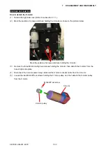
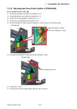
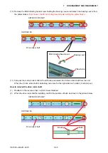
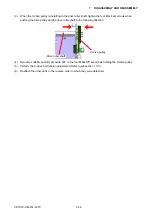
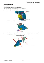
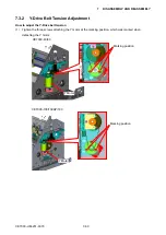
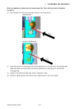
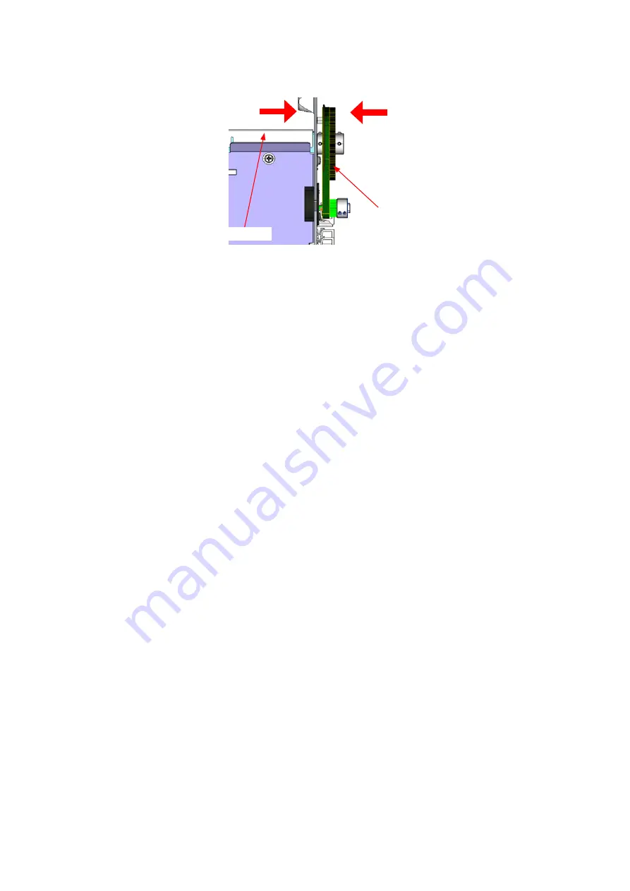
(3) When the X drive pulley is installing to the drive roller shaft, tighten the four M3L4 set screws while
pushing the drive pulley and the drive roller shaft to the following direction.
Drive roller shaft
X drive pulley
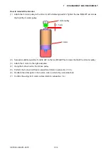
(4) Spread a suitable quantity of Loctite 222 on the four M3L4WP set screws holding the X-drive pulley.
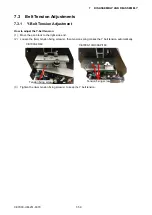
(5) Perform the X-drive belt tension adjustment (Refer to subsection 7.3.3.).
(6) Reattach the other parts in the reverse order in which they were detached.
Summary of Contents for CE7000-130
Page 1: ...CE7000 UM 251 00 9370 CUTTING PLOTTER SERVICE MANUAL CE7000 40 60 130 160 130AP ...
Page 2: ......
Page 4: ...CE7000 UM 251 9370 II ...
Page 72: ...CE7000 UM 251 9370 5 2 5 RECOMMENDED PARTS LIST ...
Page 74: ......


