


CE7000-UM-251-9370 7-38
7 DISASSEMBLY AND REASSEMBLY
CE7000-130/130AP/160
How to detach the vacuum fan 1
(1) Detach the right side cover (Refer to subsection 7.1.1.).
(2) Detach the front guide (Refer to subsection 7.1.5.).
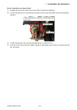
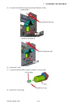
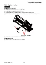
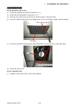
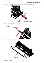
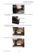
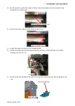
(3) Disconnect the cable of vacuum fan from the J1007 connector on the main board.
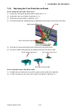
(4) Remove the M3L6 binding head screw holding the fan cover on the bottom of plotter, and then detach it.
M3L6 binding head screw
Fan cover
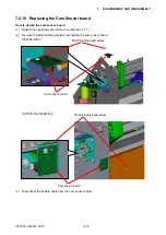
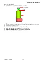
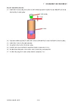
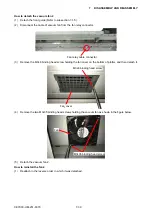
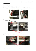
(5)
Remove the two M3L35 binding head screws holding the vacuum fan as shown in the figure below.
M3L35 binding head screw
Fan
(6) Detach the vacuum fan 1.
How to reinstall the fan 1
(1) Reattach in the reverse order in which it was detached.
Summary of Contents for CE7000-130
Page 1: ...CE7000 UM 251 00 9370 CUTTING PLOTTER SERVICE MANUAL CE7000 40 60 130 160 130AP ...
Page 2: ......
Page 4: ...CE7000 UM 251 9370 II ...
Page 72: ...CE7000 UM 251 9370 5 2 5 RECOMMENDED PARTS LIST ...
Page 74: ......


