


CE7000-UM-251-9370 7-4
7 DISASSEMBLY AND REASSEMBLY
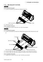
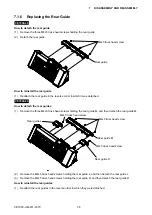
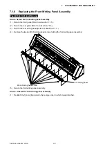
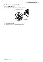
7.1.5 Replacing the Front Guide
CE7000-40
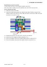
How to detach the front guide
(1) Remove the three M4L5 truss head screws holding the front guide.
Front guide
M4L5 truss head screw
(2) Detach the front guide.
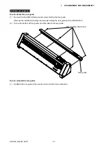
How to reinstall the front guide
(1) Reattach the front guide in the reverse order in which it was detached.
CE7000-60
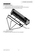
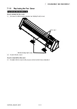
How to detach the front guides
(1) Remove the three M4L5 truss head screws holding the front guide M, and then detach the front guide
M.
Front guide M
Front guide L
Front guide R
M4L5 truss head screw
M4L5 truss head screw
M4L5 truss head screw
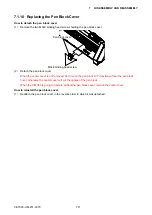
(2) Remove the M4L5 truss head screws holding the front guide L, and then detach the front guide L.
(3) Remove the M4L5 truss head screws holding the front guide R, and then detach the front guide R.
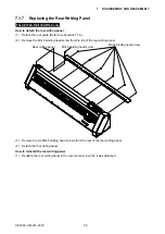
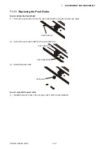
How to reinstall the front guides
(1) Reattach the front guides in the reverse order in which they were detached.
Summary of Contents for CE7000-130
Page 1: ...CE7000 UM 251 00 9370 CUTTING PLOTTER SERVICE MANUAL CE7000 40 60 130 160 130AP ...
Page 2: ......
Page 4: ...CE7000 UM 251 9370 II ...
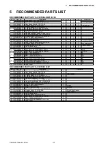
Page 72: ...CE7000 UM 251 9370 5 2 5 RECOMMENDED PARTS LIST ...
Page 74: ......


