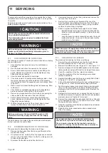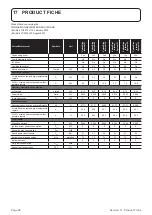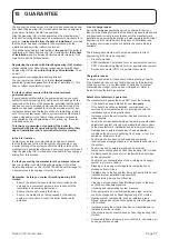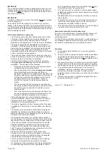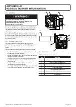
Section 11: Servicing
Page 46
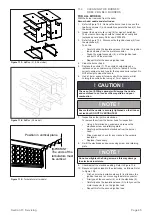
Burner air inlet cover
This is located on the right hand side of the burner. Refer to
Figure A1-1 in Appendix A1 towards the back of this manual.
1. Unscrew and remove the two screws and remove the air inlet
cover from the burner.
2.
Check inside and remove any debris, leaves, hair, fluff, etc.
from the air inlet cover and air damper..
3.
Check the condition of the rubber seal around the air inlet
cover. Replace if damaged or missing.
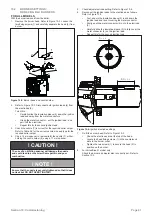
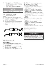
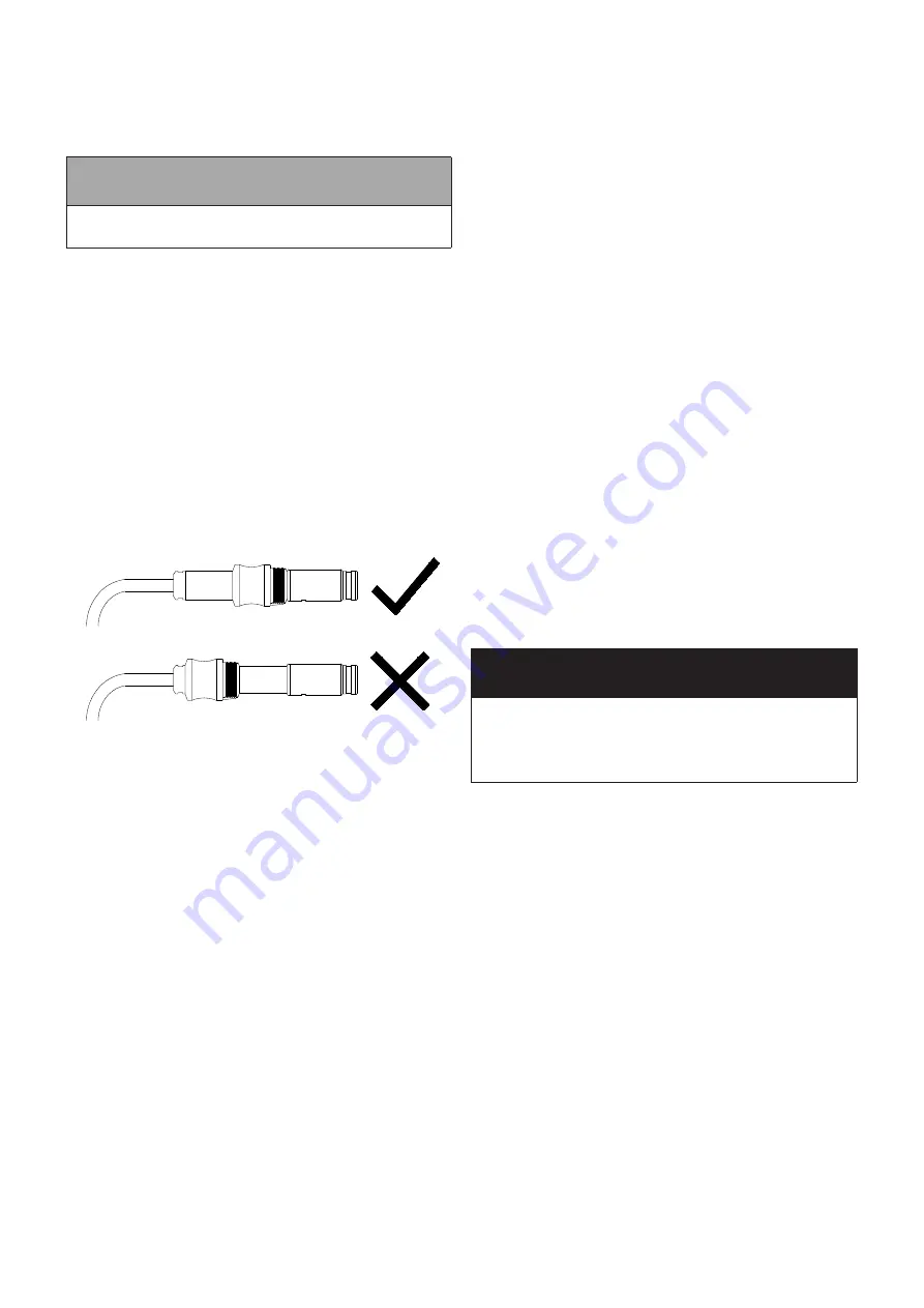
Figure 11-4:
UV Cell Collar Position
11.
Re-fit the burner head. Refer to Figure 10-3.
•
Check that the electrodes are at the top of the head.
•
Locate the head fixing screws (1) in the countersunk
slots in the burner collar.
•
Tighten the two screws (1) to secure the head (2) in
position on the burner.
! NOTE !
When re-fitting the burner head ensure that the ignition
leads do not obscure the UV cell.
11.5
CLEANING THE BURNER:
OTHER COMPONENTS
UV Cell
The UV cell is a push-fit in the front of burner body. Refer to
Figure A1-1 in Appendix A1 towards the back of this manual.
1.
Holding the body of the UV cell and NOT the cable, carefully
pull the UV cell out of the burner.
2.
Clean the sensor end of the UV cell.
3.
Check the sliding collar on the UV cell is positioned as far
forward as possible on the body of the UV cell. Refer to
figure 11-4.
4. Replace UV cell back in the burner and check that it is fully
pushed in.
Burner fan housing
This is located over the fan impeller. Refer to Figure A1-1 in
Appendix A1 towards the back of this manual.
With the burner air inlet cover already removed:
1. Unscrew and remove the four screws and remove the fan
housing from the burner.
2.
Check and clean the fan impeller and remove any debris,
leaves, hair, fluff etc.
3.
Check the fan housing is clean and clean as required.
4.
Check the rubber seal around the fan housing. Replace if
damaged or missing.
5.
Re-fit the fan housing to the burner and secure with the four
screws.
6.
Check the air adjuster disc (VortexBlue 21 model only). Refer
to Section 10.3 for details.
7.
Re-fit the air inlet cover to the burner and secure with the two
screws.
Oil pump filter
This is located under the end cover on the oil pump. Refer to
Figure A1-1 in Appendix A1 towards the back of this manual.
1. Unscrew and remove the four cap screws securing the pump
end cover.
2.
Remove the filter and wash in kerosene.
3.
Check the O-ring seal around the end cover. Replace if
damaged.
4.
Replace the filter and end cover.
5.
Re-fit the four cap screws, tightening evenly, to secure the
end cap.
11.6 AIR ADJUSTER DISC:
VORTEXBLUE 21 MODEL ONLY
Refer to Section 10.3.
11.7 RECOMMISSIONING
! WARNING !
To ensure safe and efficient operation of the boiler it is
important that re-commissioning is carried out, especially
combustion checks (%CO
2
level, flue gas temperature and
smoke number) after the boiler has been serviced. Refer to
the Commissioning instructions in Section 10.

