

Section 9: Flue System and Air Supply
Page 39
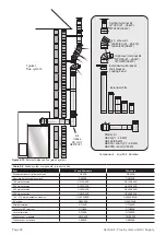
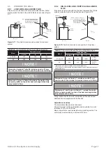
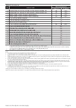
Table 9-8:
Flue clearances
Ref
Location of outlet
Minimum distance (mm)
Pressure jet
Condensing
A
Directly below an opening, air brick opening, opening window, etc.
600
1,000 **
B
Horizontally to an opening, air brick opening, opening window, etc.
600
1,000 **
C
Below a gutter, eaves or balcony with protection
75 *
1,000 **
D
Below a gutter, eaves or balcony without protection
600
1,000 **
E
From vertical sanitary pipework
300
F
From an internal or external corner
300
G
Above ground or balcony level
300
H
From a surface or boundary facing the terminal
600
2,500 **
J
From a terminal facing the terminal
1,200
K
Vertically from a terminal on the same wall
1,500
L
Horizontally from a terminal on the same wall
750
M
Above the highest point of an intersection with the roof
600
N
From a vertical structure to the side of the terminal
750
O
Above a vertical structure less than 750 mm from the side of the terminal
600
P
From a ridge terminal to a vertical structure on the roof
1,500
Q
Above or to the side of any opening on a flat or sloping roof
300
R
Below any opening on a sloping roof
1,000
S
From oil storage tank (Class 1)
1,800 ***
*
**
***
A heat shield at least 750 mm wide must be fitted to provide protection of combustible material.
Clearances required by BS 5410-1:2019 to alleviate the effect of plume nuisance. If a risk assessment shows that there will be no impact from pluming,
then the ‘pressure jet’ figure could apply - seek confirmation from Local Authority Building Control.
Seek guidance from OFTEC Book 3 (Oil Storage and Supply).
NOTES
1.
Appliances burning class D fuel have additional restrictions. Refer to BS 5410-1:2019.
2.
Vertical structure in N, O and P includes tank or lift rooms, parapets, dormers, etc.
3.
Terminating positions A to L are only permitted for appliances that have been approved for low level flue discharge when tested in accordance with BS EN 303-1, OFS A100 or OFS
A101.
4.
Terminating positions should be at least 1.8 metres from an oil storage tank (Class 1) unless a wall with at least 30 minutes fire resistance and extending 300 mm higher and wider than
the tank is provided between the tank and the terminating position.
5.
Where a flue is terminated less than 600 mm away from a projection above it and the projection consists of plastics or has a combustible or painted surface, then a heat shield of at least
750 mm wide should be fitted to protect these surfaces.
6.
If the lowest part of the terminal is less than 2 metres above the ground, balcony, flat roof or other place to which any person has access, the terminal should be protected by a guard.
7.
Notwithstanding the dimensions given above, a terminal should not be sited closer than 300 mm to combustible material. In the case of a thatched roof, double this separation distance
should be provided. It is also advisable to treat the thatch with a fire retardant material and close wire in the immediate vicinity of the flue.
8.
A flue or chimney should not pass through the roof within the shaded area delineated by dimensions Q and R.
9.
Where protection is provided for plastics components, such as guttering, this should be to the standard specified by the manufacturer of the plastics components.
10. Terminals must not be sited under car ports.
11.
Terminals at low levels (terminals under 2.1 metres) have more restrictive recommendations and should not be positioned near public footways, frequently used access routes, car
parking spaces less than 2.5 metres from the terminal or patio’s (hard surface area).
Further guidance can be obtained from BS 5410-1:2019, OFTEC Book 4 (Installation) and Approved Document J.
Grant UK flue products are fully compliant with the CE (Communauté Européenne/European Community) standards having undergone rigorous product testing.


