background image

Page 16

Section 4: Installation

4.9  FILLING THE HEATING SYSTEM

Refer to Section 7.2 (Filling the Sealed System)

4.10  BEFORE YOU COMMISSION

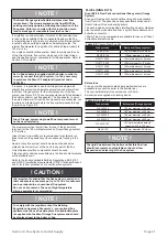
To avoid the danger of dirt and foreign matter entering the boiler 

the complete heating system should be thoroughly flushed 

out – both before the boiler is connected and then again after 

the system has been heated and is still hot. This is especially 

important where the boiler is to be installed on an older system.
For optimum performance after installation, the boiler and the 

associated heating system must be flushed in accordance with 

the guidelines given in BS 7593 (Treatment of water in domestic 

hot water central heating systems). This must involve the use 

of a proprietary cleaner, such as Sentinel X300 (new systems), 

Sentinel X400 (existing systems), or Fernox Restorer.
After cleaning, it is vitally important that all traces of the cleaner 

are thoroughly flushed from the system.

For long term protection against corrosion and scale, after 

cleaning/flushing a suitable inhibitor should be added to the 

system water, such as Sentinel X100 or Fernox MB-1, in 

accordance with the manufacturers’ instructions. 
Failure to follow the above will invalidate the guarantee.
If the boiler is installed in a garage or out house, in order to 

provide further protection should there be a power failure in cold 

weather, a combined anti-freeze and corrosion inhibitor can 

be used such as Sentinel X500 or Fernox Alphi-11. Follow the 

manufacturers’ instructions supplied to achieve the level of anti-

freeze protection required.
For details of the Sentinel Products visit www.sentinel-solutions.

net and for Fernox products visit www.fernox.com.

Grant UK strongly recommends that a Grant Mag One in-line 

magnetic filter/s (or equivalent*) is fitted in the heating system 

pipework. This should be installed and regularly serviced in 

accordance with the filter manufacturer’s instructions.
* As measured by gauss. The MagOne magnetic filter has a gauss 

value of 12000.

4.11 COMPLETION

Following installation of the boiler, instruct the user in the 

operation of the boiler, the boiler controls, the heating controls and 

the safety devices.

Please ensure that the OFTEC CD/10 installation completion 

report (provided with the boiler) is completed in full, leaving the 

top copy with the user and retain the carbon copy for your own 

records.
Ensure that the User Handbook (supplied with the boiler) is 

handed over to the user.

Summary of Contents for VortexBlue VTXBF21

Page 1: ...UK DOC 0129 Rev 1 0 June 2020 Grant VortexBlue Internal and Internal System Condensing Oil Boiler Range Installation and Servicing Instructions ...

Page 2: ...arning CAUTION Caution concerning likely damage to equipment or tools as a consequence of not following the instructions in the caution NOTE Used for emphasis or information not directly concerned with the surrounding text but of importance to the reader PRODUCT CODES AND SERIAL NUMBERS COVERED The serial numbers used on Grant oil boilers consist of a fifteen digit numerical code with the final th...

Page 3: ...ecting the power supply 24 8 3 Connecting an external frost thermostat 25 8 4 Boiler control panel wiring diagrams 26 8 5 Control system wiring diagrams 28 Contents Page 3 9 FLUE SYSTEM AND AIR SUPPLY 30 9 1 Air supply 30 9 2 Conventional flue systems 30 9 3 Connecting a conventional flue 33 9 4 Balanced flue systems 33 9 5 Prepare the wall 37 9 6 Flue clearances 38 10 COMMISSIONING 40 10 1 Before...

Page 4: ...ensing boilers Refer to Section 9 2 for further details Where a rigid conventional flue is required Grant recommends the use of the Grant Hybrid flue system which uses components from the Grant Orange and Green flue systems Refer to Figure 9 4 for details This flue system is suitable for all Grant VortexBlue oil boilers The Orange system flue components used for the internal part of the Hybrid sys...

Page 5: ... on Please note that the mains on neon does not necessarily indicate that the burner is firing See Boiler Indicator Lights information in the next column When the ON OFF switch is set to on the POWER indicator LED on the control panel will also light This also does not necessarily indicate that the boiler is firing NOTE If the ON OFF switch is set to off the boiler will NOT supply central heating ...

Page 6: ...r motor power Watts 90 Absorbed motor power kW 0 15 Starting current Amps 2 0 Running current Amps 0 85 Oil connection BSP male on end of flexible fuel hose Conventional flue draught mbar Minimum 0 087 maximum 0 37 in wg Minimum 0 035 maximum 0 15 Maximum operating pressure sealed open system bar 2 0 Maximum operating pressure pressure relief valve bar 2 5 Boiler type ON OFF 2 2 SEALED SYSTEM DATA...

Page 7: ... 21kW 26 26kW 36 31 5kW 7 When setting the 21 to 15kW the burner air adjuster disc Grant UK product code Z20094349 must be fitted and positioned to disc setting B Refer to Section 10 3 This disc is NOT supplied with the boiler but can be obtained free of charge by contacting Grant UK 8 The combustion door test point may be used for CO2 and smoke readings only Do not use this test point for tempera...

Page 8: ...nsate drain outlets FRONT VIEW 470 860 LEFT SIDE VIEW 813 759 709 587 352 18 17 110 30 Flue centre line RIGHT SIDE VIEW PLAN VIEW 470 603 1 1 0 Safety valve Cold fill Flow 22mm push fit 170 Flue spigot Figure 2 1 VortexBlue Internal and Internal System 21 and 26 dimensions ...

Page 9: ...ernal and Internal System 36 dimensions Safety valve Flow 28mm push fit Cold fill 61 170 61 LEFT SIDE VIEW 455 555 311 24 115 63 63 Flue centre line RIGHT SIDE VIEW PLAN VIEW 470 603 150 FRONT VIEW 470 900 205 Flue spigot Alternative condensate drain outlets ...

Page 10: ...th the fire valve sensor located above the burner A spring clip for mounting the sensor is supplied fitted to the boiler on the rear of the control panel The fire valve should be located after the second 15 micron filter i e between the filter and the point at which the oil line enters the building Refer to Figures 3 1 to 3 3 The fire valve must have an operating temperature of between 90 and 95 C...

Page 11: ...2 6 12 9 7 4 8 5 4m Max 300mm Min Min 1 2 3 2 6 12 9 7 4 8 5 11 3 5m Max 10 Key to oil supply diagrams 1 Oil tank 5 External wall 9 Burner 2 Isolating valve 6 Oil filter 15μm max filtration size 10 Non return valve 3 Oil strainer 7 Fire valve sensor 11 De aerator 4 Fire valve to BS5410 1 8 Oil pump 12 Appliance isolation valves Position of de aeration device must be level with or above the oil pum...

Page 12: ...ly at the same level as or above the burner oil pump Refer to Figure 3 3 1 4 BSP female connections Tiger Loop SUPPLY TO PUMP RETURN FROM PUMP SUPPLY FROM TANK Figure 3 4 Tiger loop de aeration device An external deaerator must not be fitted within 500 mm of a flue terminal Always follow the manufacturers installation instructions supplied with the deaerator To use a de aertor the following additi...

Page 13: ...4 Fit the ʺ isolating valve not supplied to the end of the rigid oil return pipe to the deaerator or oil tank using a fitting to suit the pipe size and type not supplied 5 Connect the other end of the flexible fuel hose not supplied to the isolating valve using a ʺ x ʺ BSP adaptor not supplied 6 Re fit the burner to the boiler Section 3 Oil Storage and Supply System Page 13 3 2 1 SINGLE PIPE GRAVI...

Page 14: ...liquid fuel firing Non domestic installations This standard should be followed with regard to installations with an output capacity in excess of 70kW Where the combined outputs of multiple appliances located together at a domestic dwelling exceed 70kW then then a dedicated plant room as specified in BS 5410 2 is recommended BS EN 12828 Heating systems in buildings Design for water based heating sy...

Page 15: ...code MPCBS62 UNDERFLOOR PIPEWORK Plastic pipe may be used on underfloor floor systems where the plastic pipe is fitted after the thermostatic mixing valve Copper tube must be used for at least the first metre of flow and return primary pipework between the boiler and the underfloor mixing blending valves 4 6 CONNECTIONS 4 6 1 FLOW AND RETURN CONNECTIONS Refer to Section 5 4 6 2 CONDENSATE CONNECTI...

Page 16: ...h the manufacturers instructions Failure to follow the above will invalidate the guarantee If the boiler is installed in a garage or out house in order to provide further protection should there be a power failure in cold weather a combined anti freeze and corrosion inhibitor can be used such as Sentinel X500 or Fernox Alphi 11 Follow the manufacturers instructions supplied to achieve the level of...

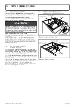
Page 17: ...d holes taking care not to distort the side panel 5 2 WATER CONNECTIONS SYSTEM MODELS A 15 mm discharge pipe must be connected to the safety valve outlet connection The pipework between the safety valve and the boiler must be unrestricted that is no valves The discharge pipe should be run to the outside of the building and terminate so that it cannot cause injury to persons or property A 15 mm dou...

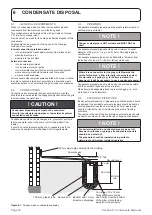
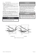
Page 18: ... be plastic plastic waste or overflow pipe is suitable NOTE Copper or steel pipe is NOT suitable and MUST NOT be used Condensate disposal pipes should have a minimum nominal diameter of 22 mm ʺ e g use 21 5 mm OD polypropylene overflow pipe Condensate disposal pipes must be fitted with a fall away from the boiler of at least 2 5 45 mm fall per metre run NOTE Where it is not possible for the pipe t...

Page 19: ... soil stack the sealing cap must be fitted in the trap outlet On external discharge systems to a hopper gully or soakaway the sealing cap should be removed from the trap outlet If there is any discharge of condensate from the overflow outlet this could indicate a blockage possibly due to freezing Turn off the boiler and investigate the cause If neccesary contact your service engineer for assistanc...

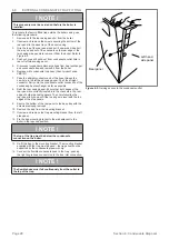
Page 20: ...nto the condensate outlet connection of the condensing heat exchanger as far as possible 8 Refit the rear casing panel Ensure that both edges of the rear panel are correctly located into the channels in the rear edge of both side casing panels Then carefully slide the rear panel fully down until the top edges is level with the top edges of the side panels 9 Secure the bottom of the rear panel to t...

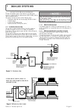
Page 21: ...NTS All Grant VortexBlue models are suitable for use with sealed systems complying with the requirements of BS EN 12828 BS EN 12831 and BS EN 14336 The system must be provided with the following items Diaphragm expansion vessel complying with BS EN 13831 Pressure gauge Pressure relief safety valve Approved method for filling the system 7 1 1 EXPANSION VESSEL The expansion vessel should be fitted i...

Page 22: ...valve as follows 1 Turning the head of the valve anticlockwise until it clicks The click is the safety valve head lifting off its seat allowing water to escape from the system 2 Check that the water is escaping from the system 3 Top up the system pressure as necessary by following the procedure outlined in Section 7 2 7 1 4 FILLING LOOP Provision should be made to replace water lost from the syste...

Page 23: ...ction CAUTION Do not pressurise the vessel above 1 5 bar NOTE The air pressure in the vessel must be checked annually The central heating system volume using the expansion vessel as supplied must not exceed the recommended value Refer to Section 2 2 If the system volume is greater an extra expansion vessel complying with BS 4841 must be fitted as close as possible to the central heating return con...

Page 24: ...t in damage to the burner This will not be covered by the boiler product guarantee There is no facility in the Grant VortexBlue Internal and Internal System boilers for the fitting of a plug in timer or programmer A 4 core cable 3 core and earth is required to connect the power supply and heating controls to the boiler On non system models a 3 core cable 2 core and earth is required to connect the...

Page 25: ...d will operate as follows to protect the boiler from freezing First the heating circulation pump will operate for a period of 15 minutes If after that time the air temperature sensed exceeds 10 C the pump will stop If after the 15 minutes the temperature is less than 10 C the burner will fire and continue to do so until the flow thermistor detects a temperature of 30 C when the burner will stop Th...

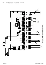
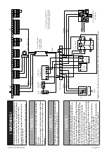
Page 26: ...POCKET FLOW THERMISTOR TO TOP POCKET MAINS 1A 2A 4B 5B Boiler On Off 2 C Limit Thermostat Earth connection boiler top bracket Printed Circuit Board FUSE 5 X 20 E N L N L Black Cable 230V 5A Fused Supply N E Flow Thermistor Black shroud indicates Flow Thermistor Link Pump Burner Resistor BURNER PERMANENT LIVE DO NOT CONNECT DO NOT CONNECT DO NOT CONNECT DO NOT REMOVE LINK DO NOT REMOVE LINK SL L Li...

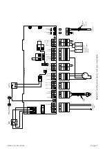
Page 27: ...MISTOR TO FRONT POCKET FLOW THERMISTOR TO TOP POCKET MAINS 1A 2A 4B 5B Boiler On Off 2 C Limit Thermostat Earth connection boiler top bracket Printed Circuit Board FUSE 5 X 20 E N L N L Black Cable 230V 5A Fused Supply N E Flow Thermistor Black shroud indicates Flow Thermistor Link Pump Burner Resistor BURNER PERMANENT LIVE DO NOT CONNECT DO NOT CONNECT DO NOT CONNECT DO NOT REMOVE LINK DO NOT REM...

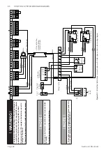
Page 28: ...rown Brown Pump Brown Blue Green Yellow E N L Brown Black SL Figure 8 3 VortexBlue Internal and Internal System with S plan type control system wiring diagram WARNING The boiler must be wired as shown in this wiring diagram i e with both a permanent live PL supply AND a separate switched live SL from the heating system controls No permanent live PL supply to the boiler can result in damage to the ...

Page 29: ...esent For correct operation the orange wire from the 3 port valve MUST be connected to the coil of the relay as shown in the wiring diagram See Figure 8 4 A suitable relay is available to purchase on request from Grant UK with product code VBFYPR This requirement does NOT apply to S plan type systems using 2 port zone valves Refer to Figure 8 3 Cylinder Stat N 2 Channel Programmer L N E 240V 50HZ ...

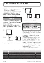
Page 30: ...r supply for conventional flue boilers 9 2 CONVENTIONAL FLUE SYSTEMS NOTE Under no circumstances can Grant Vortex boilers be installed with existing flue systems Only flue systems and components suitable for wet flues should be used Failure to install the correct type of flue system will invalidate the guarantee Grant condensing boilers have high operating efficiencies and low flue gas temperature...

Page 31: ... are satisfactory the flue should terminate with a standard cowl Refer to the locally applicable Building Regulations BS 5410 1 and OFTEC Installation Requirements OFTEC Technical Books 2 and 4 for further guidance on conventional flue systems CAUTION It is important to ensure that the flue system is sealed and that condensate cannot escape Up to 1 5 l h of condensate can be produced in a conventi...

Page 32: ...iner is directional see Section 9 2 Note Terminal Adjustable section 235 300mm WXA250 100 100mm dia Locking band C 45 elbow O Top plate Clamp Figure 9 3 Grant Orange flue system in a typical brick chimney Green System components refer to Table 9 5 Orange System components refer to Tables 9 2 and 9 3 Boiler flue connector from CFA 15 70 kit Adaptor from CFA 15 70 kit Boiler Figure 9 4 Hybrid flue s...

Page 33: ... boiler flue outlet to the outer face of the wall is 4 metres with or without elbows included No more than 2 x 45 or 1 x 90 elbow should be fitted per system The low level balanced flue Yellow system is supplied with a stainless steel guard This must be fitted in all circumstances to prevent objects from entering the flue outlet The guard must be fitted centrally over the flue terminal and securel...

Page 34: ...m from the top of the boiler flue outlet to the terminal is 12 metres for all Grant Vortex boilers HIGH LEVEL HORIZONTAL SYSTEM This version of the White system allows the flue to rise vertically within the building before exiting horizontally through the wall by utilising a terminal with a 90 bend The maximum flue length for this system from the top of the boiler flue outlet to the outer face of ...

Page 35: ...balanced flue Yellow system and the external Tee allows the connection of a twin wall insulated flue pipe and a combustion air inlet providing a room sealed flue system The external system can terminate at either high level or vertically above roof level as required See Figure 9 10 The minimum dimensions for locating the terminal from building features windows doors etc are shown in Figure 9 13 Th...

Page 36: ...ternal balanced flue green system Table 9 5 Green system components product codes Item 21 and 26 models 36 models Standard starter kit stainless steel GK90B GK200B Short starter kit stainless steel GK90SB GK200SB 150 mm extension GX150 90B GX150 200B 250 mm extension GX250 90B GX250 200B 450 mm extension GX450 90B GX450 200B 950 mm extension GX950 90B GX950 200B 195 270 mm adjustable extension GXA...

Page 37: ...is dimension is given with the boiler pushed back against the rear wall Any clearances must be added to it Hole to be cut in wall Hole to be cut in wall Boiler centre line Outline of boiler Rear exit Side exit Standard kit with no extensions D C A A B Figure 9 12 Flue hole dimensions and position for high level system Table 9 7 High level balanced flue hole cutting dimensions Model Dimension mm A ...

Page 38: ...Section 9 Flue System and Air Supply Page 38 9 6 FLUE CLEARANCES Figure 9 13 Flue clearances ...

Page 39: ...mitted for appliances that have been approved for low level flue discharge when tested in accordance with BS EN 303 1 OFS A100 or OFS A101 4 Terminating positions should be at least 1 8 metres from an oil storage tank Class 1 unless a wall with at least 30 minutes fire resistance and extending 300 mm higher and wider than the tank is provided between the tank and the terminating position 5 Where a...

Page 40: ...ing door and check it is fitted correctly and that a good seal is made 7 Unscrew the burner fixing nut located at the top of the mounting flange and remove the burner from the boiler 8 Check adjust the burner settings as described in Section 10 2 Burner Settings 9 Re fit the burner to the boiler and tighten the fixing nut DO NOT OVERTIGHTEN 10 COMMISSIONING 10 Check that the sealed system has been...

Page 41: ...nner CAUTION The use of an ill fitting spanner will damage the nozzle and could lead to an incorrect flame pattern and poor combustion NOTE Ensure that the nozzle is securely tightened so that it does not leak but DO NOT OVER TIGHTEN 5 Check adjust electrode setting Refer to Figure 10 4 6 Reconnect the ignition leads to the electrodes as follows Refer to Figure 10 3 First ensure the insulative sle...

Page 42: ...ut reset button on the burner lights wait about 45 seconds and press the reset button to restart the ignition process This procedure may have to be repeated several times during first lighting 5 With the burner alight check the fuel pressure Refer to Section 2 3 burner settings 6 Adjust the pressure if necessary refer to Figure A1 1 in Appendix A1 towards the back of this manual NOTE It is importa...

Page 43: ... A suitable antifreeze should be used to prevent damage to the boiler in areas where electrical power failure can occur in winter months 4 Replace the top front and rear panels as necessary NOTE After commissioning the boiler complete the OFTEC CD 11 commissioning report Leave the top copy with the user and retain the carbon copy If the boiler is to be left in service with the User set the control...

Page 44: ...isconnect the flexible air tube from the burner 4 Unscrew and remove the two fixing screws and remove the red cover from the burner 5 Remove the burner fixing nut located at the top of the mounting flange and withdraw the burner from the boiler If required disconnect the flexible oil line s using a suitable container to prevent any oil spillage 6 Check or replace the flexible fuel supply hose as f...

Page 45: ...e for the required boiler output Do NOT attempt to clean the nozzle 6 Use a 16 mm spanner to remove re fit the nozzle whilst holding the nozzle holder using a 17 mm spanner CAUTION The use of an ill fitting spanner will damage the nozzle and could lead to an incorrect flame pattern and poor combustion NOTE Ensure that the nozzle is securely tightened so that it does not leak but DO NOT OVERTIGHTEN...

Page 46: ...check that it is fully pushed in Burner fan housing This is located over the fan impeller Refer to Figure A1 1 in Appendix A1 towards the back of this manual With the burner air inlet cover already removed 1 Unscrew and remove the four screws and remove the fan housing from the burner 2 Check and clean the fan impeller and remove any debris leaves hair fluff etc 3 Check the fan housing is clean an...

Page 47: ...l pressure may be too high check and adjust 2 Burner pulses Insufficient air supply check the air damper setting and the condition of the fan Check room ventilation is adequate see Section 9 1 Check the nozzle size and type 3 Flame slow to stabilise during start up Insufficient air supply check the air damper setting and the condition of the fan Check room ventilation is adequate see Section 9 1 C...

Page 48: ...control circuit that drives the oil valve faulty Eeprom error Immediate during pre purge ORANGE GREEN blinking inverted Faulty internal memory 12 3 BURNER FAULT DIAGNOSTICS Table 12 3 Burner faults Faults Possible cause Fault diagnostics Solutions The burner does not start when there is heat demand Lack of electrical supply OFF Check presence of voltage in the L N of the four pin plug Check the co...

Page 49: ...ken Replace or reset electrodes Replace nozzle Flame goes out then relights 230V to motor across blue and black wire Remove extraneous light Replace pump coupling Check oil pipe from pump to nozzle holder Clear blockage Boiler or flue blocked Approx 35 Ω across blue and black motor wire D Coil lead OK Replace UV sensor Replace oil pump Ignition leads OK Replace coil Clean or replace pump and fuel ...

Page 50: ... head all models before November 2019 VBS126 Wilo Para SC HE circulating pump 7m head all models from November 2019 VBS159 Temperature Control PCB c w sensors all models MPCBS54E Temperature Control PCB w o sensors all models MPCBS96 Central Heating Sensor for PCB all models MPCBS97 Manual Air Vent MPCBS68 Automatic Air Vent MPCBS29 Low Pressure Switch Upgrade Kit all internal models MPCBS62 A 13 ...

Page 51: ...on gives an exploded view of the Riello burners in the Grant VortexBlue boilers and a parts list associated with them 2 1 34 3 4 8 7 30 33 10 30 15 32 9 6 31 26 23 25 12 24 22 16 11 21 29 20 19 5 27 28 14 13 18 17 35 16 Figure 13 1 Exploded view of Riello RDB BLU burner ...

Page 52: ...5126 Z20095126 12 Capacitor 4 5 μF ü ü ü 20071576 Z20071576 13 Solenoid valve ü ü ü 3007871 Z3007871 14 Pump pressure regulator ü ü ü 20032135 Z20032135 15 Air adjuster disc ü N A N A 20094349 Z20094349 16 Oil pump ü ü ü 20030953 Z20030953 17 O ring pump filter 10 pack ü ü ü 3007175 Z3007175 18 Pump filter and o ring ü ü ü 3020436 Z3020436 19 Oil hose connector 3 8 x 1 4 ü ü ü 3003602 Z3003602 20 ...

Page 53: ...owing Directives 2006 95 EEC Conforms with the safety objectives of the Low Voltage Directive and its amending directives 2004 108 EC Conforms with the essential protection requirements of the Electromagnetic Compatibility Directive and its amending directives 92 42 EC Conforms with the requirements of the Boiler Efficiency Directive 2010 30 EU Conforms with the Labeling of Energy related products...

Page 54: ...scription Sealant and adhesive Known Hazards Irritation to eyes Precautions Avoid inhalation of vapour contact with eyes and prolonged or repeated contact with skin After handling always follow normal good hygiene practices Protection Use eye protection Rubber or plastic gloves should be worn where repeated contact occurs and a face mask worn when working in confined spaces First Aid Eyes Flush ey...

Page 55: ...he boiler refer to the information given in the Servicing section of the Installation Servicing Instructions provided with the boiler RECYCLING Many of the materials used in Grant oil boilers can be recycled these are listed in the table below COMPONENT MATERIAL Outer casing panels Mild steel polyester powder coated Primary heat exchanger and baffles Mild steel Secondary heat exchanger Stainless s...

Page 56: ...ure regime P1 kW 6 3 7 8 10 8 6 3 7 8 10 8 Auxiliary electricity consumption At full load elmax kW 0 13 0 13 0 15 0 13 0 13 0 15 At part load elmin kW 0 039 0 039 0 049 0 039 0 039 0 049 In standby mode PSB kW 0 0 0 0 0 0 Useful efficiency Seasonal space heating energy efficiency ƞs 91 71 91 71 94 56 91 71 91 71 94 56 At rated heat output and high temperature regime ƞ4 93 6 93 6 95 1 93 6 93 6 95 ...

Page 57: ... burner Ensure the problem is not being caused by the heating system or its controls Consult the boiler handbook for guidance Free of charge repairs During the two year guarantee period no charge for parts or labour will be made provided that the boiler has been installed and commissioned correctly in accordance with the manufacturer s installation and servicing instructions it was registered with...

Page 58: ...re to do so does not affect your statutory rights1 The balance of the guarantee is transferable providing the installation is serviced prior to the dwelling s new owners taking up residence Grant Engineering UK Limited must be informed of the new owner s details The Company will endeavour to provide prompt service in the unlikely event of a problem occurring but cannot be held responsible for any ...

Page 59: ...r is used the blue flame cannot be detected by the usual photocell A digital control box is used the UV cell cannot be used with the usual analogue control box A clear reset button on the control box with burner status and fault identification by the use of different coloured indicator lights A longer combustion head to allow the necessary recirculation of the combustion gases A post purge followi...

Page 60: ...e reset push button immediately The reset push button indicator LED will then display the last lockout indication e g constant red Refer to the Fault Diagnostics table in Section 12 4 of this installation manual to identify the fault from the indicator LED sequence The lockout fault will only be displayed for a period of 10 seconds If required this period can be extended by re pressing the reset p...

Page 61: ... by a new heat request 60 A1 4 2 Presence of Extraneous light or Flame On burner start up when the fan starts to pre purge the burner boiler if an extraneous light or flame is detected in the combustion chamber by the UV sensor the burner fan continues to run until either a The extraneous light or flame disappears or b 25 seconds elapses a burner lockout occurs and the fault indicator LED flashes ...

Page 62: ... fuel no ignition etc must be identified and rectified A1 4 6 Post Purge Function This function allows air flow through the burner for a pre set time after the burner flame is switched off on the loss of demand for the burner to fire The loss of demand from either the heating system controls or boiler temperature control interrupts the switched live to the burner resulting in the fuel supply being...

Page 63: ...the electronic control changes the differential pressure setpoint to be maintained by the pump in a linear fashion between Hs the value set using the red selector knob on the pump control panel and Hs The differential setpoint varies linearly with the volume flow Q A2 1 3 INDICATOR LED The pump is fitted with an indicator LED This is located around the circumference of the red selector knob See Fi...

Page 64: ...l operation N A Flashes red and green Pump is operating but stopped Pump restarts itself after fault has disappeared Undervoltage Voltage 160V OR Overvoltage Voltage 253V Check supply voltage is 195V V 253V Overheating temperature inside motor too high Check water and ambient temperature Flashes red Pump not operating Pump stopped blocked Pump does not restart itself due to a permanent failure Rep...

Page 65: ...Condensate drain openings 4 around motor 8 Run Fault signal LED 4 Housing screws 9 Display of selected control mode 5 Control module 10 Display of selected pump curve I II III A3 1 3 PUMP COMPONENTS A3 1 4 CONTROL PANEL Indicator LEDs Run Fault signal LED item 8 Figure A3 1 LED is GREEN when pump is running in normal pump operation LED lights up red flashes when there is a fault refer to Section A...

Page 66: ...e of decreasing volume flow in the pipework There are three pre defined pump curves I II and III to choose from Constant Differential Pressure Mode p c Recommended for underfloor heating systems In this mode the electronic control maintains the set delivery head irrespective of the volume flow from the pump There are three pre defined pump curves I II and III to choose from Constant Speed Mode Rec...

Page 67: ... to pump control electrics Pump is not connected to power supply Check cable connection LED is damaged Check if pump is running Electronics are damaged Replace pump Manual Restart Unblocking Function The pump will attempt an automatic restart if a blackage is detected If this is not successful the Run Fault LED will be constant RED To activate the manual restart unblocking function Press and hold ...

Page 68: ...GRANT ENGINEERING UK LIMITED Hopton House Hopton Industrial Estate Devizes Wiltshire SN10 2EU Tel 44 0 1380 736920 Fax 44 0 1380 736991 Email info grantuk com www grantuk com ...

Reviews: