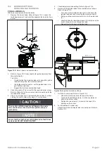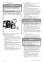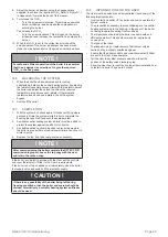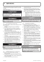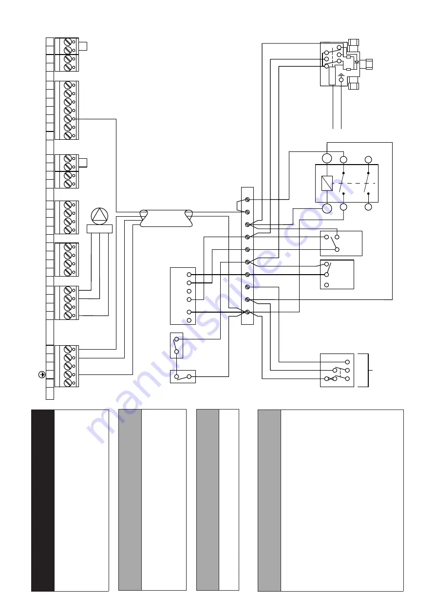
Section 8: Electrical
Page 29
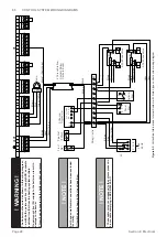
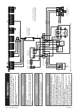
Figure
8-4:
VortexBlue
Internal
and
Internal
System
with
Y-plan
type
control
system
wiring
diagram
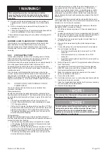
! WARNING !
The boiler must be wired as shown in this wiring diagram, i.e. with both a permanent live (PL) supply
AND a separate
switched live (SL) from the heating system controls.
No permanent live (PL) supply to the boiler can result in damage to the burner
.
This will not be covered by the boiler product guarantee.
! NOTE
!
* These cable colours correspond to the colours present in 4-core cable complying to BS EN 50525-2-1
1
! NOTE
!
Do NOT connect the orange wire from the 3-port valve directly to terminal 19 (SL) on the boiler control panel (via terminals 9 and 10 in the wiring centre).
When
the
heating
demand
is
satisfied,
a
voltage
of
between
50-150V can remain on the orange wire from the 3-port valve. If connected to terminal 19 (SL) of the boiler control panel, the boiler will continue to operate in the heating mode, as if a heating demand is still present.
For correct operation, the orange wire from the 3-port valve MUST be connected to the coil of the relay
, as shown in the
wiring diagram. See Figure 8-4.
A suitable relay is available to purchase on request from Grant UK, with product code: VBFYPR.
This requirement does NOT apply to S-plan type systems using 2-port zone valves. Refer to Figure 8-3.
Cylinder
Stat
N
2-Channel
Programmer
L N E
240V 50HZ
5A
1
2
3
4
5
6
7
8
9
10
L
Frost
Stat
Pipe Stat
(If fitted)
Wiring Centre
Link
OFF OFF ON ON HW HT HW HT
3-Port Mid Position
Zone Valve
2
C
1
2 1 3
Room
Stat
1
2
3
4
5
6
7
8
9
10
11
12
18
20
21
22
15
16
13
14
25
26
23
24
17
19
N
PL
- -
-
-
-
-
-
4 Core cable from
Controls Wiring
Centre to Boiler
Motor
13k
2W
270k
0.25W
Brown
Grey*
Green/Yellow
Brown
Blue
Green/Yellow
Orange
Grey
White
Blue
Green/Yellow
Black* (Switch Live)
Link
Link
Brown
Blue
Green/Yellow
E
N
L
Brown
Black
SL
A1
A2
1
2
3
4
Y-Plan Relay**
**Product code: VBFYPR
Terminals 3 and 4 of this relay
are to be left disconnected.
! NOTE
!
Earth and some Neutral connections have been excluded for clarity
.
All switches are shown in the closed position, except those in the relay (see Figure 8-4), which are shown in the open position.


