Section 11: Servicing
Page 45
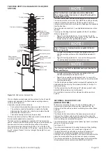
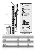
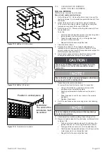
Figure 11-1:
Baffles (21 & 26 model)
Figure 11-2:
Baffles (36 model)
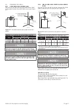
IMPORTANT:
The ends of the
turbulators must
be vertical
Position in vertical plane
Figure 11-3:
Turbulators (all models)
11.4
CLEANING THE BURNER:
RDB2.2 BG BLU BURNERS
FOR ALL MODELS
With the burner removed from the boiler:
Burner head, nozzle and electrodes:
1. Refer to Figure 10-3. Remove the burner head. Loosen the
two fixing screws (1) and carefully separate the head (2) from
the burner.
2. Inspect the burner collar o-ring (8) for signs of perishing.
The burner collar o-ring should be inspected annually and
replaced as necessary. Part code: Z3008878.
3. Refer to Figure 10-3. Disconnect both ignition leads (4) from
the electrodes (5)
To do this:
•
Carefully slide the insulation sleeve (3) down the ignition
lead and away from the metal connector.
•
Grasp the metal connector (4) - not the ignition lead -
and pull it off the electrode.
•
Repeat this for the second ignition lead.
4.
Clean the burner head.
5. Replace the nozzle (7). The nozzle should always be
replaced on an annual service. Refer to Table 2-3 for the
correct nozzle size and type for the required boiler output. Do
NOT attempt to clean the nozzle.
6.
Use a 16 mm spanner to remove/re-fit the nozzle, whilst
holding the nozzle holder using a 17 mm spanner.
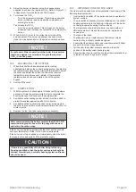
! CAUTION !
The use of an ill-fitting spanner will damage the nozzle
and could lead to an incorrect flame pattern and poor
combustion.
! NOTE !
Ensure that the nozzle is securely tightened so that it does
not leak but DO NOT OVERTIGHTEN!
7.
Inspect/clean the ignition electrodes.
To remove them from the burner head for inspection:
•
Using a 3mm allen key, unscrew and remove the
electrode screw and retaining plate.
•
Carefully withdraw both electrodes from the burner
head.
•
Wipe clean and check for any cracks in the ceramic
insulation.
•
Replace if necessary.
8.
Re-fit the electrodes and secure using screw and retaining
plate.
! NOTE !
Do not overtighten the fixing screw as this may damage
the electrode insulators.
9.
Check/adjust the electrode setting. Refer to Figure 10-4.
10. Reconnect ignition leads to the electrodes, as follows. Refer
to Figure 10-3.
•
First, ensure the insulation sleeve (3) is slid down the
ignition lead and is not covering the metal connector.
•
Firmly push the connector (4) on to the electrode (5).
•
Carefully slide the insulation sleeve (3) to fully cover the
metal connector (4) on the ignition lead.
•
Repeat this for the second ignition lead.

