A1.3 DIGITAL CONTROL BOX
The digital control box fitted to this burner has several different
features compared to the more commonly used 'analogue' control
box.
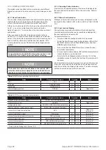
A1.3.1 Reset Push-button
This is a clear (transparent) button that will indicate the operating
status of the burner and also burner faults depending on the
colour of the indicator LED visible through the reset button.
If there is no heat demand to fire the burner, the indicator LED will
be off, i.e. no colour visible though the reset push button.
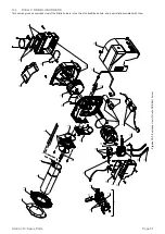
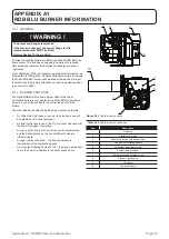
Refer to Figure A1-1 for the location of the control box and reset
push-button.
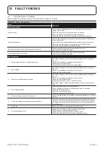
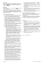
If the reset push-button LED is indicating a lockout (refer to
Section A1.3.3), press the reset button to attempt to re-start the
burner. If the burner then operates correctly the lockout may have
been caused by a temporary fault that has now cleared. If the
lockout persists the cause of the fault should be diagnosed and
rectified.
A1.3.2 Operating Status Indication
From start up the operating status of the burner is displayed via
the reset push-button indicator LED on the control box. Refer to
Table A1-2.
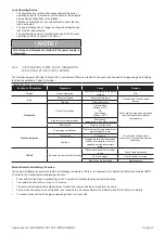
A1.3.3 Burner Fault Indication
Whenever a burner lockout occurs the cause is displayed via the
reset push-button indicator LED on the control box. Refer to Table
A1-3.
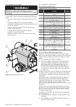
A1.3.4 Last Lockout Display
The control box memorises the details of the last lockout that
occurred and this information can be recalled and displayed by
the reset push-button indicator LED.
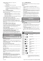
To operate this function:
•
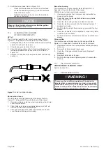
Press and hold the reset push-button for 25 seconds.
•
During this time the reset push button indicator LED will first
flash RED (twice) and then flash GREEN (once) and then
GREEN again (three times).
•
As soon as it flashes GREEN four times release the reset
push-button immediately.
•
The reset push-button indicator LED will then display the last
lockout indication, e.g. constant red.
•
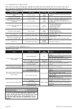
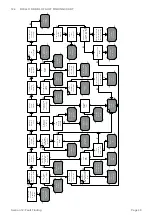
Refer to the Fault Diagnostics table in Section 12.4 of this
installation manual to identify the fault from the indicator LED
sequence.
The lockout fault will only be displayed for a period of 10 seconds.
If required, this period can be extended by re-pressing the reset
push-button during the display of the lockout. The lockout display
will then be extended by a further 10 seconds.
Table A1-2:
Burner operating status indicator
Status
Reset push-button colour
Seconds
Notes
OFF
OFF
-
-
Pre-purge
ORANGE blinking
0.5
0.5
Safety time
GREEN blinking
0.5
0.5
Normal operating position
GREEN
-
-
Steady ON
Table A1-3:
Burner operating status indicator
Status
Reset push-button colour
Seconds
Notes
Extraneous light (false flame signal)
GREEN, RED blinking alternately
0.5
0.5
Frequency supply error
ORANGE
-
-
Steady ON
Voltage monitor error
ORANGE, GREEN fast blinking alternately
0.2
0.2
Reset push-button / remote reset anomaly
GREEN, RED fast blinking alternately
0.2
0.2
Lockout for no flame after safety time
RED
-
-
Steady ON
Go to box A*
Lockout for false flame signal
RED blinking
0.5
0.5
Go to box B*
Lockout for maximum number of re-cycles
RED fast blinking
0.2
0.2
Go to box C*
Lockout for fan motor error
RED, ORANGE blinking inverted
2.5
0.5
Go to box D*
Lockout for oil valve error
RED, GREEN blinking inverted
2.5
0.5
Go to box E*
Lockout for eeprom error
ORANGE, GREEN blinking alternately
0.5
0.5
Go to box F*
* Refer to the fault finding chart - Section 12.4.
! NOTE !
To operate the reset push-button it must be pressed in and
briefly held (for at least one second) before releasing.
! NOTE !
The burner can only be reset 5 times consecutively, after
which the mains power supply has to be switched off and
then back on for a further 5 reset attempts to be available.
Appendix A1: RDB BLU Burner Information
Page 60

