


! WARNING !
Ensure that the electrical supply has been isolated before
making any connections to the boiler.
8.1 GENERAL
Grant VortexBlue models require a ~230V 1ph 50Hz supply, which
must be protected by a 5 Amp fuse.
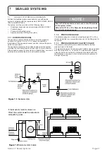
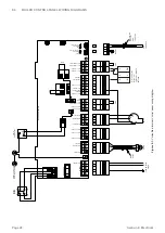
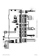
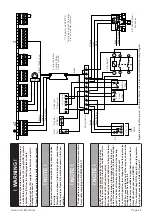
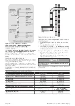
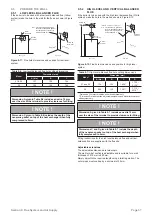
Refer to Figures 8-1 and 8-2 for control panel wiring diagrams.
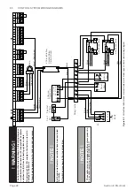
Refer to Figures 8-3 and 8-4 for typical control system wiring
diagrams for all models.
! WARNING !
The Vortex boiler contains electrical switching equipment
and must be earthed.
The supply must be fused at 5 Amp and there must only be one
common isolator for the boiler and control system, providing
complete electrical isolation.
A fused double pole switch or a fused three pin plug and shuttered
outlet socket should be used for the connection.
The power supply cable should be at least 0.75 mm
2
PVC as
specified in BS 6500, Table 16.
All the wiring and supplementary earth bonding external to
the boiler must be in accordance with the current IET Wiring
Regulations.
Any room thermostat or frost thermostat used must be suitable for
use on mains voltage.
In the event of an electrical fault after installation of the boiler, the
following electrical system checks must be carried out:
•
Short circuit
•
Polarity
•
Earth continuity
•
Resistance to earth
! NOTE !
If the supply cord is damaged, it must be replaced by
the manufacturer, its service agent or similarly qualified
persons in order to avoid a hazard.
8.2
CONNECTING THE POWER SUPPLY
8.2.1 CONNECTING POWER SUPPLY, PUMP
AND CONTROL SYSTEM
The boiler requires both a switched live, from an external
programmer or control system AND a permanent live power
supply.
This permanent live supply is essential for the fan post purge
operation.
Failure to fit BOTH a switched live and permanent live may cause
damage to the burner.
! NOTE !
Do not interrupt the permanent mains supply to the boiler
with any external control, e.g. a timer, programmer, or
room thermostat.
! WARNING !
The boiler must be wired as shown in Figures 8-3 and
8-4, i.e. with both a permanent live supply AND a separate
switched live (from the heating system controls).
No permanent live supply to the boiler can result in
damage to the burner.
This will not be covered by the boiler product guarantee.
There is no facility in the Grant VortexBlue Internal and Internal
System boilers for the fitting of a plug-in timer or programmer.
A 4-core cable (3-core and earth) is required to connect the power
supply and heating controls to the boiler.
On non-system models a 3-core cable (2-core and earth) is
required to connect the circulating pump to the boiler.
For typical control system wiring diagrams, please refer to Figures
8-3 and 8-4.
! NOTE !
Ensure that the route and length of the supply and pump
cables are such that the boiler control panel can be fully
hinged down without needing to disconnect them from the
terminal block.
The procedure to connect the power supply is as follows:
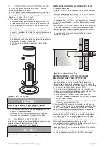
1.
Lift off the boiler top front casing panel, if it has not already
been removed.
2. Loosen (do not remove) the four screws securing the control
panel to the side panels, hinge the panel forward and allow it
to drop down to gain access to the top of the panel.
3. Remove the two screws securing the terminal block cover
and lift off the cover.
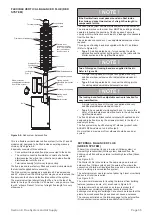
4. Remove the screws securing the cable clamp and open the
clamp.
5. Route the supply cable through the hole in the rear panel
(using the grommet supplied) and up the control panel.
6.
Pass the 4-core cable through the cable clamp and connect
to the boiler control panel terminals as follows:
•
Green/Yellow to mains earth (terminal 1)
•
Grey* to mains neutral (terminal 2)
•
Brown to mains live (terminal 3)
•
Black* to switched live (terminal 19)
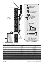
On non-system models - pass the 3-core cable from the
pump through the cable clamp and connect to the boiler
control panels as follows:
•
Green/Yellow to pump earth (terminal 4)
•
Blue to pump neutral (terminal 5)
•
Brown to pump live (terminal 6)
7.
Make the remaining required connections to the control
panel, as detailed in this section.
8. Secure the cable(s) in the cable clamp
9.
Place the terminal block cover in position over the terminal
block, taking care not to trap any wires and secure in position
with the two M4 screws provided.
10.
Close the hinged panel and tighten the four screws securing
the control panel to the side panels.
11. Replace the top casing panels.
12.
Ensure that all external wiring is adequately supported.
Section 8: Electrical
Page 24
8 ELECTRICAL


