Page 831
Assembly of the cylinder
head
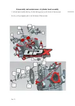
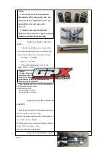
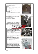
1. Install the valve spring lower seat
(3) and the oil shield (4) to the valve
guide;
2. After applying a small amount of
lubricating oil to the intake valve rod (1)
and exhaust valve rod (2), install the
valve guide, install the valve outer
spring (5), the valve inner spring (6), and
the valve spring upper seat ( 7) and valve
lock clip (8);
3. Use the valve remover to depress the
valve spring, and then install the valve
lock clip into the valve spring seat;
Notice:
To prevent permanent deformation of the
valve spring, do not compress the spring too
much to fit the valve lock clip.
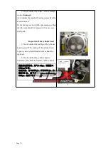
4. Check whether the valve lock clip is in
place;
5. Carry out the air tightness test on the
assembled cylinder head combination. If the air
tightness test of the cylinder head combination is
qualified, the next step can be performed
(assemble according to the cylinder head
composition diagram);
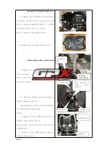
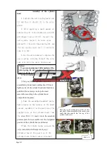
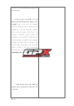
6. Take the assembled camshaft parts,
apply grease on the surface of the small
journal, assemble it at the position of the
camshaft hole of the cylinder head, take
the
screw M6
×
12, insert it into the camshaft
pressure plate hole, assemble it at the designated
position of the cylinder head, and fasten;
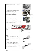
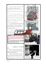
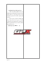
7.
Take the intake rocker arm and the
valve rocker arm shaft respectively, and
assemble them at the position of the
cylinder head intake rocker arm shaft
This side is the cutting edge of the rocker
arm shaft. When assembling the rocker arm
shaft, this side should face the top of the
cylinder head cover
M6
×
18


