NOTICE:
Vary the capacity with the regulating valve in the discharge line. Never throttle the flow from the
suction side. This action can result in decreased performance, unexpected heat generation,
and equipment damage.
Piping guidelines
Guidelines for piping are given in the Hydraulic Institute Standards available from the Hydraulic Institute
at 9 Sylvan Way, Parsippany, NJ 07054-3802. You must review this document before you install the
pump.
Alignment criteria for pump flanges
Type
Criteria
Axial
The flange gasket thickness ±0.8 mm | 0.03 in.
Parallel
Align the flange to be within 0.001 mm per mm | in. per in. of the flange diameter to 0.8mm | 0.03 in.
max.
Concentric You can easily install the flange bolts by hand.
The above criteria are based on the following references from API RP 686, 2nd Edition:
4.6.3 The machine and piping flange faces shall be parallel to less than 10 micrometers per centimeter |
0.001 in. per in. of pipe flange outer diameter up to a maximum of 750 micrometers | 0.030 in. For piping
flange outer diameters smaller than 25 cm | 10 in., the flanges shall be parallel to 250 micrometers |
0.010 in. or less. For special- purpose machinery, pipe to machinery flange spacing measurements shall
be recorded on the Piping alignment datasheet shown in Figure B.4. For raised face flanges, feeler
gauge readings shall be taken at the raised face. For flat faced flanges, feeler gauge readings shall be
taken at the flange outside diameter.
4.6.4 Flange face separation shall be within the gasket spacing ±1.5 mm | 1/16 in. Only one gasket per
flanged connection shall be used.
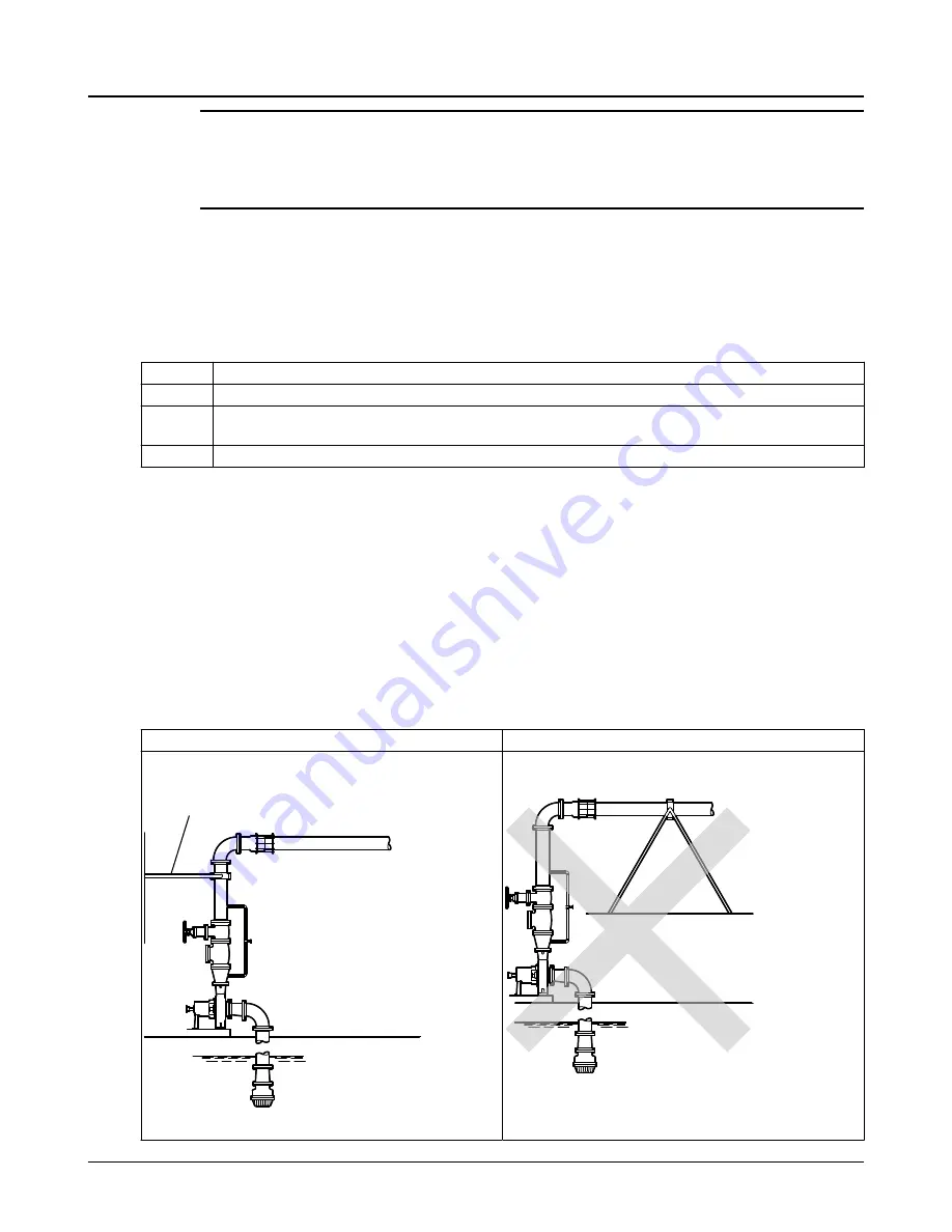
Example: Installation for expansion
Correct
Incorrect
This illustration shows a correct installation for expan-
sion:
1
1.
Expansion loop/joint
This illustration shows an incorrect installation for expan-
sion:
4.6 Piping checklists
36
Model 3700i API610 / Type OH2 Installation, Operation, and Maintenance Manual


