


- 23 -
System Hardware Installation
3-4 Installing the CPU and Heat Sink
Read the following guidelines before you begin to install the CPU:
Make sure that the motherboard supports the CPU.
Always turn off the system and unplug the power cord from the power outlet before installing the
CPU to prevent hardware damage.
Unplug all cables from the power outlets.
Disconnect all telecommunication cables from their ports.
Place the system unit on a flat and stable surface.
Open the system according to the instructions.
WARNING!
Failure to properly turn off the server before you start installing components may cause serious
damage. Do not attempt the procedures described in the following sections unless you are a
qualified service technician.
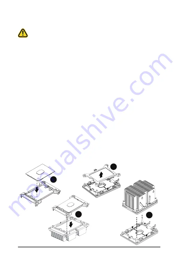
Follow these instructions to install the CPU:
1. Align the processor to the carrier so that the gold triangle on the processor aligns with the triangle
on the carrier, and then install the processor into the carrier.
NOTE:
Apply thermal compound evenly on the top of the CPU.
2.
Carefully flip the heatsink over. Align the carrier assembly so that the triangle on the carrier aligns
with the triangle on the heatsink, and then install the carrier assembly onto the bottom of the
heatsink.
3. Remove the CPU socket cover.
NOTE:
Save and replace the CPU socket cover if the processor is removed from its socket.
4. Align the heatsink to the CPU socket using the guide pins and make sure the gold triangle is in the
correct orientation. Then place the heatsink onto the top of the CPU socket.
5. Secure the heatsink by tightening the screws in sequential order (1
g
2
g
3
g
4).
NOTE:
When removing the heatsink, loosen the screws in reverse order (4
g
3
g
2
g
1).
1
2
3
4
Summary of Contents for E251-U70
Page 1: ...E251 U70 E251 U71 Edge Server 2U Intel Xeon Scalable server system User Manual Rev 1 0 ...
Page 10: ... 10 This page intentionally left blank ...
Page 15: ... 15 Hardware Installation 1 3 System Block Diagram ...
Page 16: ...Hardware Installation 16 This page intentionally left blank ...
Page 28: ...System Hardware Installation 24 1 2 4 3 ...
Page 38: ...System Hardware Installation 24 12V Power Cable CPU Power Cable ...
Page 39: ... 23 System Hardware Installation GPU Card Power Cable RIser Card Power Cable ...
Page 44: ...Motherboard Components 44 This page left intentionally blankThis ...
Page 64: ...BIOS Setup 64 5 2 11 Intel R I210 Gigabit Network Connection ...
Page 66: ...BIOS Setup 66 5 2 12 VLAN Configuration ...