background image

Setting Up

66

2

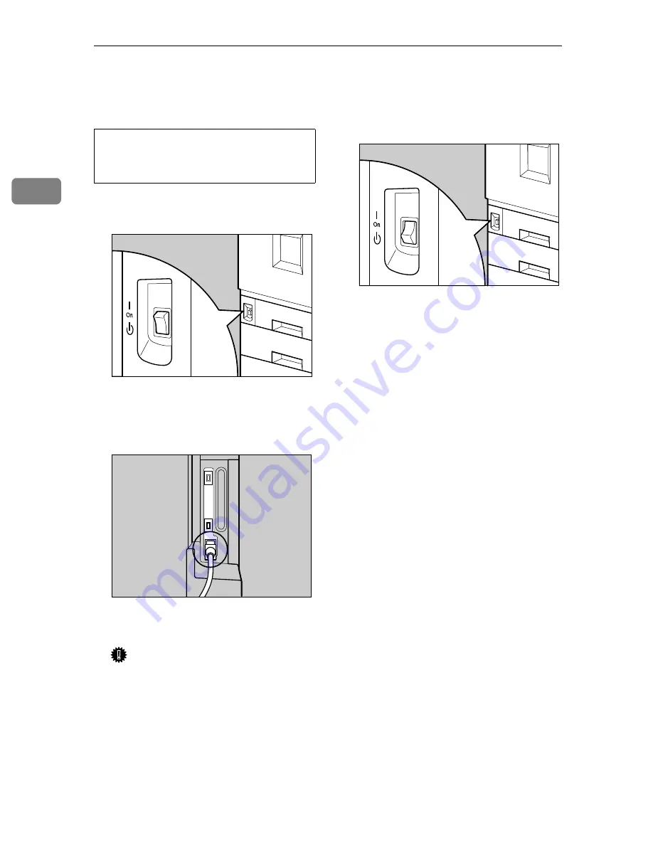
Turning the Power On

R


WARNING:

A

Confirm that the power switch is
set to "

c

c

c

c

 Stand by".

B

Connect the power cable to the
connector on the back of the
printer.

C

Plug in the power cable.

Important

Make sure the power cable is
plugged securely into the wall
outlet.

Turn the power switch off when
plugging and unplugging the
power plug.

D

Turn the power switch to "

a

a

a

a

 On".

Plug and unplug the power ca-
ble with dry hands, or it could 
result in an electric shock.

ZDJH029N

Stand by

ZDJH030J

ZDJH031N

Stand by

Summary of Contents for DSc38

Page 1: ...Setup Guide Read this manual carefully before you use this product and keep it handy for future reference For safety please follow the instructions in this manual...

Page 2: ...ed in a factory or at a location with the requisite equipment The laser subsystem is replaceable in the field by a qualified Customer Engineer The laser chassis is not repairable in the field Customer...

Page 3: ...companies We disclaim any and all rights in volved with those marks Notes Some illustrations might be slightly different from your machine Certain options might not be available in some countries For...

Page 4: ...of an emergency it can be unplugged easily Disconnect the power plug by pulling the plug not the cable if the power cable or plug becomes frayed or damaged To avoid hazardous electric shock or laser...

Page 5: ...nt Do not eat or swallow toner Keep toner used or unused and toner cartridge out of reach of children For environmental reasons do not dispose of the equipment or expended supplies at a household wast...

Page 6: ...machine model meets the ENERGY STAR Guidelines for energy efficiency The ENERGY STAR Guidelines intend to establish an international energy saving system for developing and introducing energy efficien...

Page 7: ...instruction is not followed paper might be misfed or data might be lost Be sure to read this Preparation This symbol indicates the prior knowledge or preparations required before op erating Note This...

Page 8: ...Installing the 1394 Interface Unit Type1045 31 Installing the User Account Enhance Unit TypeB 34 Installing the Printer Hard Disk Type 3800C 37 Installing the Duplex Unit Type 3800C 41 Installing the...

Page 9: ...e detail This high resolution can be output at the speed of 14 ppm Versatile Options with the New Generation Controller With the new high speed 64 bit controller architecture and the new RPCS command...

Page 10: ...ray for printing Exclusive for 11 81 2 K paper 6 Tray 2 Loads up to 500 sheets of plain paper in this tray for printing 7 Standard Tray Output is stacked here with the print side down 8 Upper Right Co...

Page 11: ...obstruct the ventilator A mal function may occur due to overheating Remove the ventilator to replace the in ternal dustproof filter 2 Connector Connect the main power cable cables from options etc to...

Page 12: ...appropriate toner cartridge 5 Photoconductor Unit The printer comes with one black Photo conductor Unit and three color yellow cyan magenta Photoconductor Units When Replace Color PCU Type A ap pears...

Page 13: ...does not match with the actual set size or type 5 Menu key Press this key to make and check the cur rent printer settings 6 Power indicator Power indicator is on while the power switch is on Power in...

Page 14: ...Getting Started 6 1...

Page 15: ...more than necessary These actions could damage the cable A frayed or damaged cable might cause an electrical and fire hazard Do not handle the plug with wet hands Doing this might cause an elec trica...

Page 16: ...cm 22 inch or more D 70 cm 28 inch or more Optimum Environmental Conditions Possible and recommended temperature and humidity ranges are as follows White area Possible operation Range Gray area Recomm...

Page 17: ...may notice an odd smell To keep the workplace comfortable we recommend that you keep it well ventilated Environments to Avoid Important Locations exposed to direct sunlight or strong light Dusty area...

Page 18: ...ng items contact your sales or service representative Manuals and CD ROMs Description form Setup Guide This manual Maintenance Guide 1 Administrator Reference 1 Printer Client Reference 1 CD ROM Print...

Page 19: ...artridge K Magenta M Cyan C Yellow Y Toner Cartridges Paper Feed Unit Labels Additional Documentations Note This package does not include an interface cable Please purchase one for use with your host...

Page 20: ...ay 1 C Remove the adhesive tape and sheet of paper D Close Tray 1 slowly E Open Tray 2 F Remove the adhesive tape and sheet of paper G Close Tray 2 slowly H Open the front cover slowly by pulling down...

Page 21: ...avoid printer mal function during operation The removed tape is dirty Be careful not to let it touch your hands or clothes L Close the front cover slowly by pushing the two areas on the left and right...

Page 22: ...a stable and level place E Take out the Fuser Oil Unit from the bag and remove seal A A A A and then seal B B B B as shown in the il lustration Note Be sure to remove seal A and then pull it out in a...

Page 23: ...Be careful not to get oil on the metal part of the left side of the Fuser Oil Unit G Holding the green handle with one hand use your other hand to push the front area of the handle to a slight slant a...

Page 24: ...rips on both sides The machine could break or cause an injury if dropped A Install the 500 1000 sheet Paper Feed Unit or 2000 sheet Large Capacity Tray PAPER FEED UNIT Type 3800C Paper Bank PS 470 Ins...

Page 25: ...nstall the 2 Tray Finisher SR770 Attach the SR770 to the left side of the printer You cannot install the SR770 unless both the Paper Feed Unit and Duplex Unit options are installed If you choose to in...

Page 26: ...column of paper P 26 Installing the Paper Bank PS470 2000 sheet Large Capacity Tray 4 SR770 2 Tray Finisher Performs Job Separation staples and punches holes Install the Finisher on the left side of...

Page 27: ...e 2 Tray Finisher and 4 bin Mailbox at the same time Interior 1 Memory Unit Type B SDRAM Module Attach 64MB 128MB or 256MB RAM into the slot of the Controller Board P 29 Installing the Memory Unit Typ...

Page 28: ...nstall these options If you have already installed the optional Duplex Unit 2 Tray Fin isher and 4 bin Mailbox remove all these options before installing the optional Paper Feed Unit Important Before...

Page 29: ...When installing multiple options install the Paper Feed Unit first R CAUTION Note The 500 sheet Paper Feed Unit weights approximately 18kg 39 7 lbs A Turn off the power switch and unplug the power ca...

Page 30: ...t Close the tray of the 500 sheet Paper Feed Unit tightly F Pull out Tray 2 slowly while lift ing it up a little G Fasten one thumb screw Use a coin to fasten it tightly H Slide Tray 2 back into the p...

Page 31: ...tallation for printing you can check whether the 500 sheet Paper Feed Unit is installed properly Print the Configuration Page from the List Test Print menu If it is installed properly you will see Pap...

Page 32: ...on of the Paper Feed Unit you want to place When installing multiple options install the Paper Feed Unit first R CAUTION Note The 1000 sheet Paper Feed Unit weights approximately 25kg 55 2 lbs A Turn...

Page 33: ...ake out the packaged items making sure there are two thumb screws and one mounting brack et Close the tray of the 1000 sheet Paper Feed Unit tightly F Pull out Tray 2 slowly while lift ing it up a lit...

Page 34: ...in stalled properly reinstall from step A If you cannot install it properly even after reinstalla tion contact your sales or ser vice representative Reference P 68 Test Printing Installing the Paper...

Page 35: ...r slowly into place Important Four persons should hold the handles located on two sides of the printer to move it D Take out the packaged items making sure there are two thumb screws and one mounting...

Page 36: ...mb screw Use a coin to fasten it tightly K Close the right cover of the 2000 sheet Large Capacity Tray L Stick label 3 above the handle on the front of the 2000 sheet Large Capacity Tray Note After fi...

Page 37: ...an damage the unit Do not subject the SDRAM Mod ule to physical shocks A Turn off the power switch and unplug the power cable B Remove two screws that are fas tening the Controller Board on the back o...

Page 38: ...sure to return the provided screwdriver to its original posi tion on the inside of the front cover Note After finishing all installation for printing you can check whether the Memory Unit is in stalle...

Page 39: ...f it happens an error message appears The printer can ac cept data sent from other PCs only after the first print job has finished Bidirectional transmissions are not supported by the 1394 Interface U...

Page 40: ...ler Board slowly E Put the Controller Board in a flat place F Remove the small cover plate us ing provided screwdriver as shown in the illustration Note You will not use the removed screws G Install t...

Page 41: ...return the provided screwdriver to its original posi tion on the inside of the front cover Note After finishing all installation for printing you can check whether the 1394 Interface Unit is installed...

Page 42: ...ttery is inside the User Account Enhance Unit If you are disposing the Unit sepa rate the IC2 lithium battery from the board and dispose of them ac cording to local regulations Important Be sure to to...

Page 43: ...er Board on the back of the printer using pro vided screwdriver Reference See P 20 How to Use the Screw driver The removed screws will be used later to fasten the Controller Board D Holding the handle...

Page 44: ...r Account En hance Unit is connected firmly to the Controller Board G Tighten the screw to fasten the User Account Enhance Unit using provided screwdriver H Adjust the Controller Board to the top and...

Page 45: ...nhance Unit is not installed properly you will see Not Installed In such a case reinstall from step A If you cannot install it prop erly even after reinstallation contact your sales or service represe...

Page 46: ...removed screws will be used later to fasten the Controller Board D Holding the handle pull out the Controller Board slowly E Put the Controller Board in a flat place F Install the Printer Hard Disk to...

Page 47: ...then push in slowly until it stops Insert the Controller Board firmly by pushing the left area as shown in the illustration L Tighten two screws to fasten the Controller Board back into its original p...

Page 48: ...n Page from the List Test Print menu If it is installed properly you will see Installed for Printer Hard Disk Drive If the Printer Hard Disk is not installed properly you will see Not Installed In suc...

Page 49: ...on D Press OK The Printer Hard Disk is format ted and a restart message is shown E Turn off the power switch once and then turn the power back on The Printer Hard Disk format is completed enabling its...

Page 50: ...cable of the Duplex Reversal Unit at this point Remove it in step G on P 44 Installing the Duplex Rever sal Unit C Turn off the power switch and unplug the power cable from the wall outlet D Lift the...

Page 51: ...the paper guide so that its right side bends down as shown in the illustration and while holding it lightly A A A A in sert it into the holes of the stand B B B B H Insert the claws of the stand into...

Page 52: ...rasp the bar inside the groove of the stand B Supporting the Duplex Reversal Unit remove the stopper of the mounting bracket on the printer This stopper will be used in a later step E so be careful no...

Page 53: ...Reversal Unit slowly and then adhere it to the printer G Remove the adhesive tape which hold the cable and then connect the cable of the Duplex Reversal Unit to the upper connector on the back of the...

Page 54: ...Open the front cover slowly by pulling the two points on the left and right B Holding the Duplex Feed Unit with both hands place it on the vertical rail and insert slowly un til it stops The vertical...

Page 55: ...cannot in stall it properly even after rein stallation contact your sales or service representative Reference See P 68 Test Printing E Check for spare parts You will not use these spare parts Installi...

Page 56: ...ast 128 MB You cannot install the 4 bin Mail box and 2 Tray Finisher at the same time A Turn off the power switch and unplug the power cable B Remove the adhesive tape and packing materials Important...

Page 57: ...the External Tray of the printer A Stand it vertically B Fold it into printer E Insert the rail with a wheel in the mounting bracket F Temporarily fasten one long screw in the position shown in the i...

Page 58: ...mount ing bracket adjusted to the posi tion shown by the arrow in the illustration fasten the left side of the mounting bracket with a long screw using provided screwdriv er Also tighten the screw on...

Page 59: ...000 sheet Paper Feed Unit or 2000 sheet Large Capacity Tray installed pro ceed to step K N If you have the 500 sheet Paper Feed Unit installed change the position of the connecting brack et on the sid...

Page 60: ...ng the cable to the 2 Tray Finisher S Connect the cable of the 2 Tray Finisher to the lower connector on the back of the printer T Install the two 2 Tray Finisher Trays to the 2 Tray Finisher Note The...

Page 61: ...isher Tray that is in stalled on the Duplex Unit back into place A Lift the top B Lower slowly Note After finishing all installa tion for printing you can check whether the Finisher is installed prope...

Page 62: ...e Important Do not remove the adhesive tape that is fastening the cable at this point Remove it in step M C Check the contents of the box Two Screws Four Output Bins Labels D Remove the top cover Draw...

Page 63: ...ck If the Duplex Unit is installed pro ceed to step G F Pull up the External Tray in the direction of the arrow A A A A and then remove B B B B G If the Duplex Unit is installed open the Duplex Revers...

Page 64: ...p L K Install the External Tray to the printer Hook the External Tray to the slits of the printer and then lower the tray toward you L If the Duplex Unit is installed re turn the Duplex Reversal Unit...

Page 65: ...box Note After finishing all installation for printing you can check whether the 4 bin Mailbox is in stalled properly Print the Con figuration Page from the List Test Print menu If it is in stalled pr...

Page 66: ...Do not incinerate spilled toner or used toner Toner dust is flammable and might ignite when exposed to an open flame Disposal should take place at an authorized dealer or an ap propriate collection si...

Page 67: ...act point with your fingers E Insert the toner cartridge slowly until the green hook snaps on the metal contact area Important Do not insert and remove the toner cartridges over and over This could re...

Page 68: ...1 P 62 Changing the settings Settings of the Paper Trays at Factory Default Tray 1 Standard 11 81 2 K exclusive 2000 sheet Large Capacity Tray Optional 11 81 2 K exclusive Reference For more informati...

Page 69: ...e stack is not higher than the Limit mark inside the tray Be sure to adjust the side guides to the paper size or paper misfeeds might occur C Slide the paper tray back slowly until it stops Tray 2 Sta...

Page 70: ...If you do the front and side guide might move Be sure to adjust the side guides to the paper size or paper misfeeds might occur Changing the settings Important Tray 1 is 11 81 2 K paper exclusive Loa...

Page 71: ...sides of the paper stack and then load it in the tray Important Confirm that the top of the stack is not higher than the Limit mark inside the tray D Pressing the green lever of the side guide A A A...

Page 72: ...nd guide A A A A move it to the position of the loaded paper B B B B G Slide the paper tray back slowly until it stops Important Do not slide the paper tray in with force If you do the front and side...

Page 73: ...t slowly until it stops B Align all four sides of the paper stack and then load two stacks next to each other Important Be sure to align the paper and load them against the left and right walls or it...

Page 74: ...k of the printer C Plug in the power cable Important Make sure the power cable is plugged securely into the wall outlet Turn the power switch off when plugging and unplugging the power plug D Turn the...

Page 75: ...U U or T T T T to display Lan guage Menu Language C Press Enter The following message appears on the panel display Language English D Press U U U U or T T T T until the lan guage you want to select a...

Page 76: ...tents to be test printed is shown C Press U U U U or T T T T to display the Config Page and then press OK List Test Print Config Page The following message appears and the Configuration Page is printe...

Page 77: ...rint er C Connect the network interface ca ble to the port on the right side of the printer D Connect the other end of the net work interface cable to network equipment such as a hub Reference For det...

Page 78: ...E 1284 and a parallel port available on the host computer Use shielded interface cables Using a cable other than a shielded cable could result in radio interference noise A Turn off the printer and ho...

Page 79: ...Guide to the Printer Exterior Front View 2 Exterior Rear View 3 Inside 4 Operation Panel 5 I Inner Cover 4 Installing Options 16 Installing the Duplex Unit Duplex Feed Unit 46 Duplex Reversal Unit 44...

Page 80: ...ay 1 2 60 Tray 2 2 61 Turning the Power On 66 U Unpacking the Printer 12 Upper Cover 2 Upper Left Cover 3 Upper Right Cover 2 User Account Enhance Unit Type B 19 User Account Enhance Unit TypeB 34 W W...

Page 81: ...Copyright 2001...

Page 82: ...UE USA G060 6900...

Reviews: