background image


Administrator Mode


4

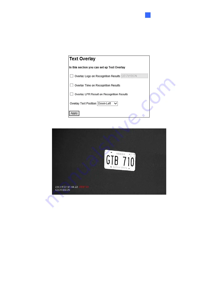
4.1.1.2  Recognition Result 

Note the function is only supported by 

GV-LPR1200

. This function allows you to display the 

recognized plate number, the date and time of recognition, or a desired text on the images of 
the recognition results. 


Figure 4-3A 


Figure 4-3B 


Overlay Logo on Recognition Results: 

Includes a desired text or description on 

recognition results. 


Overlay Time on Recognitions Results: 

Includes date stamps on recognition results.


Overlay LPR Result on Recognition Results: 

Includes the recognized plate number on 

recognition results.


Overlay Text Position: 

Select a position from the drop-down list to overlay the text on 

recognition results.


87 

Summary of Contents for GV-IP LPR Cam 5R

Page 1: ...ct or operate this product please read these instructions carefully and save this manual for future use User s Manual GV IP LPR Camera IPLPRCAM D GV LPC2210 GV LPC2211 GV LPC2011 GV LPR1200 GV LPC1200 GV LPC1100 GV IP LPR Cam 5R ...

Page 2: ...VLRQV 1R OLDELOLW LV DVVXPHG IRU LQFLGHQWDO RU FRQVHTXHQWLDO GDPDJHV DULVLQJ IURP WKH XVH RI WKH LQIRUPDWLRQ RU SURGXFWV FRQWDLQHG KHUHLQ HDWXUHV DQG VSHFLILFDWLRQV DUH VXEMHFW WR FKDQJH ZLWKRXW QRWLFH 1RWH 1R PHPRU FDUG VORW RU ORFDO VWRUDJH IXQFWLRQ IRU UJHQWLQD HR9LVLRQ QF 1R 6HF 1HLKX 5G 1HLKX LVWULFW 7DLSHL 7DLZDQ 7HO D KWWS ZZZ JHRYLVLRQ FRP WZ 7UDGHPDUNV XVHG LQ WKLV PDQXDO HR9LVLRQ WKH HR9...

Page 3: ...sion GV IP LPR Camera 5R 1 01 GV LPC1100 1 01 GV LPC1200 1 0 GV LPR1200 1 01 GV LPC2210 1 02 GV LPC2211 1 0 GV LPC2011 1 0 Note GV LPC1100 is also referred to as GV IP LPR Camera 10R IMPORTANT When using GV LPC1200 GV LPR1200 for the first time you need to remove the plastic insulation film under the battery and change the silica gel bag For details see 1 3 6 Replacing the Silica Gel Bag and 1 3 7...

Page 4: ... Sun Shield Cover 11 1 2 GV LPC1100 12 1 2 1 Feat ures 13 1 2 2 System Requirements 14 1 2 3 Packing List 15 1 2 4 Device Installation 16 1 2 5 Con necting the Camera 18 1 2 6 Replacing the Silica Gel Bag 21 1 3 GV LPC1200 LPR1200 22 1 3 1 Feat ures 23 1 3 2 System Requirements 24 1 3 3 Packing List 25 1 3 4 Inst alling the Camera 26 1 3 5 Con necting the Camera 28 1 3 6 Replacing the Silica Gel B...

Page 5: ...e ssing Your Surveillance Images 61 3 2 The Live View Window 63 3 3 The Control Panel of the Live View Window 65 3 4 Snapshot of a Live Video 69 3 5 V ideo Recording 69 3 6 Picture in Picture and Picture and Picture View 70 3 7 Alarm Notification 72 3 8 V ideo and Audio Configuration 73 3 9 Remote Configuration 74 3 10 Camera Name Display 74 3 11 Image Enhancement 74 3 12 Digit al PTZ 75 3 13 I O ...

Page 6: ...ase 122 4 3 10 Re gistry Database 123 4 4 Monito ring 125 4 4 1 Mo nitoring Settings 125 4 5 Sched ule 127 4 5 1 I O Monitoring Settings 127 4 5 2 Reco gnizing Schedule Settings 128 4 6 Network 129 4 6 1 LAN Configuration 129 4 6 2 Advanced TCP IP 131 4 6 3 UMTS 135 4 6 4 IP Filtering 137 4 6 5 SNMP Settings 138 4 7 Management 140 4 7 1 Date and Time Settings 140 4 7 2 S torage Settings 142 4 7 3 ...

Page 7: ...6 1 1 Cust omizing Camera Settings 164 6 2 Setting Up IP Cameras on GV VMS 166 6 3 Remote Monitoring with Multi View 169 6 4 Remote Monitoring with E Map 171 Chapter 7 CMS Configurations 173 7 1 Center V2 173 7 2 V ital Sign Monitor 175 7 3 Disp atch Server 176 Chapter 8 Smart Device Connection 177 Chapter 9 GV ASManager Connection 178 Specifications 181 GV IP LPR Camera 5R 181 GV LPC1100 184 GV L...

Page 8: ...ybrid DVR system at the same time GV VMS GeoVision Video Management System for IP cameras PC LPR PC LPR refers to GV DVR LPR and GV VMS LPR A GV System or GV VMS can be turned into a GV DVR LPR GV VMS LPR simply by installing the LPR Plugin and inserting an LPR Dongle PC LPRs are capable of comparing captured license plates with the database from GV ASManager vi ...

Page 9: ...482 PoE Adapter The GV PA482 PoE adapter is designed to provide power and network connection to the cameras over a single Ethernet cable The GV PA482 PoE adapter is only available for GV LPC1100 and GV LPC2210 GV PoE Switch For GV IP LPR Camera 5R GV LPC2211 LPC2011 the GV POE Switch is designed to provide power along with network connection for IP devices For other models the GV POE Switch can be...

Page 10: ...a video management system Once the camera is connected to the GV System GV VMS the resolution set on the GV System GV VMS will override the resolution set on the camera s Web interface You can only change the resolution settings through the Web interface when the connection to the GV System GV VMS is interrupted viii ...

Page 11: ... with waterproof silicon rubber or the like 3 To prevent the lens from fogging up replace the silica gel bag every time you open the camera and conceal the gel bag in camera within 2 minutes of exposing to open air The silica gel bag loses it effectiveness when the dry camera is opened 4 The camera casing can be hot due to its IR LED Make sure you unplug the power cable and allow the camera casing...

Page 12: ...ter speed to the scene and produce clear license plate capture under low light conditions The motorized varifocal lens take the advantage of its motorized focus zoom in that the user can remotely adjust the focus and zoom through the Web interface It is weather proof IP67 and also able to work in environments with temperatures ranging from 20 C 4 F to 50 C 122 F The GV IP LPR Camera 5R can be easi...

Page 13: ...speed 60 km h 37 mph Recognition for reflective license plate only Ingress protection IP67 Vandal resistance IK10 Maximum IR distance 5 M 16 4 ft Built in fan Defog Motion detection Privacy mask Text overlay IP address filtering Power supplied through PoE PoE IEEE 802 3 at Support for iPhone iPad Android and 3GPP ONVIF Profile S conformant 30 languages on Web interface 2 ...

Page 14: ...re required For details see Appendix C 2 With non IE browsers A Motion Detection Text Overlay and two way audio are not supported B The Play function is only available on the live view window Figure 3 2 C RTSP streaming must be kept as enabled For more details see 4 3 6 RTSP Compatible Software Version Model Firmware Version GV System Version GV VMS GV ASManager V1 00 V8 5 8 0 N A V4 2 GV IR LPR C...

Page 15: ... Plastic Screw Anchor x 3 Torx Wrench x 2 Sun Shield Cover Kit 1 Sun Shield Cover 2 Philips Head Screws 2 Plastic Screw Spacers and 2 Hexagon Screws included Silica Gel Bag GV IP LPR Camera Software CD GV NVR Software DVD GV ASManager Software DVD Warranty Card 4 ...

Page 16: ...oles for screw anchors 2 Insert the supplied screw anchors 3 Secure the camera to the wall using the supplied screws Figure 1 1 4 Remove the protection sticker from the camera s cover 5 Connect the camera to the network and supply power via the PoE cable See 1 1 5 Connecting the Camera 6 Access the live view See Getting Started Chapter 2 7 Based on the live view adjust the angle zoom and focus of ...

Page 17: ... and network will be supplied simultaneously PoE GV IP LPR Camera 5R Rear Panel Power LAN 10 100 Power IN Hub Router Ethernet Cable GV PA191 PoE Adapter Figure 1 2 2 When the Power LED on the front panel of the GV PA191 PoE Adapter turns green you are ready to access the live view adjust the image clarity and configure the basics See Getting Started Chapter 2 Note The GV PA191 PoE Adapter AC Power...

Page 18: ...sy and flexible installation First Shaft You can adjust the camera body by 360 degrees to the right or the left 1 Unscrew the panning lock screw with the torx wrench Torx Wrench Panning Lock Screw Figure 1 3 2 Adjust the angle of camera body to the right or the left and fasten the panning lock screw 0 360 Figure 1 4 7 ...

Page 19: ...rx wrench Torx Wrench Tilting Lock Screw Figure 1 5 2 Hold the camera body and move the camera base to the right to separate the camera gears Camera Gears Move the Camera Base to the Right Camera Body Figure 1 6 3 Adjust the angle of camera body to 90 112 5 135 157 5 or 180 Then move the camera base to the left to combine the gears 90 112 5 180 157 5 135 Figure 1 7 4 Fasten the tilting lock screw ...

Page 20: ...Shaft You can adjust the camera base by 360 1 Unscrew the base fixing screw with the torx wrench Base Fixing Screw Torx Wrench Figure 1 8 2 Adjust the angle of camera base and fasten the base fixing screw 0 360 Figure 1 9 9 ...

Page 21: ...lica Gel Bag Figure 1 11 3 Insert a new silica gel bag to the camera module and fasten the camera s cover within 2 minutes of opening the silica gel bag package IMPORTANT The silica gel loses its effectiveness when the dry ca mera is op ened To prevent the lens from fogging up re place the silica gel bag every time when you o pen the camera and conceal the gel bag in the camera within two minutes ...

Page 22: ...ra 1 Fasten the hexagon screws either on top or below the camera Figure 1 12 2 Put the sun shield cover on top of hexagon screws Make sure to aim the rear hexagon screw at the edge of the sun shield cover s aperture for optimal sun shield performance Figure 1 13 3 Fasten the Philips head screws with the plastic screw spacers Figure 1 14 11 ...

Page 23: ... plate capture for one lane under low light conditions The motorized varifocal lens take the advantage of its motorized focus zoom in that the user can remotely adjust the focus and zoom through the Web interface It is weather proof IP67 and also able to work in environments with temperatures ranging from 40 C 40 F to 50 C 122 F The GV LPC1100 can be easily configured through its Web interface and...

Page 24: ...h Recognition for reflective license plate only Ingress protection IP67 Vandal resistance IK10 Maximum IR distance 10 m 32 8 ft DC 48V High PoE PoE 120 W Built in heater and fan Support for TV out Support for I O 1 in 1 out Two way audio Defog Motion detection Privacy mask Text overlay IP address filtering Support for iPhone iPad Android and 3GPP ONVIF Profile S conformant 30 languages on Web inte...

Page 25: ...ditional settings are required For details see Appendix C 2 With non IE browsers A Motion Detection Text Overlay and two way audio are not supported B The Play function is only available on the live view window Figure 3 2 C RTSP streaming must be kept as enabled For more details see 4 3 6 RTSP Compatible Software Version Model Firmware Version GV System Version GV VMS GV ASManager GV LPC1100 V1 01...

Page 26: ... Screw x 4 Washer x 4 Torx Wrench GV PA482 PoE Adapter Power Adapter DC 48V 2 5A 120 W AC Power Cord Silica Gel Bag Adhesive tape for Silica Gel Bag GV IP LPR Camera Software CD GV NVR Software DVD GV ASManager Software DVD GV LPR Camera Installation Guide Warranty Card 15 ...

Page 27: ... Camera After you have read through the installation guides and chosen an installation site follow the steps below to install the GV LPC1100 1 Mark the installation site and drill four holes for screw anchors 2 Insert the supplied screw anchors 3 Secure the camera to the wall using the supplied screws Figure 1 15 4 Connect the camera for power and network connection See 1 2 5 Connecting the Camera...

Page 28: ... Based on the live view adjust the angle zoom and focus of the camera Loosen the indicated screw with the supplied torx wretch and adjust the joint Figure 1 16 Tilt Adjustment Figure 1 17 Pan Adjustment Figure 1 18 17 ...

Page 29: ...d of the cable to your camera 2 Insert one end of the Ethernet cable into the LAN 10 100 port on the GV PA482 Connect the other end of the cable to the hub or router connecting to your computer LAN 10 100 Power IN Figure 1 19 3 Insert the white wire of the supplied DC power adaptor into left side pin of the terminal block on the GV PA482 and the black wire to the right side pin 4 Attach the AC pow...

Page 30: ... adaptor and connect the camera to the power 1 Plug the DC power adapter to the 2 pin terminal block on the camera by inserting the wire with white lines to the pin and the black wire to the pin Figure 1 20 2 Attach the AC power cord to the DC power adaptor 3 Connect the AC power cord to a power source 19 ...

Page 31: ...5 3 Wire Definition Figure 1 21 Camera Wire Definition RJ 45 Ethernet Black BNC TV out Green RCA Audio Out Pink RCA Audio In Brown Digital Output Yellow Digital Input White GND 2 Pin Terminal Block Power 20 ...

Page 32: ...a Gel Bag Figure 1 23 3 Remove the silica gel bag and place a new bag back to its original position 4 Fasten the camera s lid within 2 minutes of replacing the silica gel bag IMPORTANT 1 The silica gel loses its effectiveness when the dry camera is opened To prevent the lens from fogging up replace the silica gel bag every time when you open the camera and conceal the gel bag in the camera within ...

Page 33: ...d focus zoom in that you can remotely adjust the focus and zoom through the Web interface It is weather proof IP67 and also able to work in environments with temperatures ranging from 40 C 40 F to 50 C 122 F GV LPR1200 is also capable of recognizing the license plate numbers with the built in LPR processor comparing captured license plates with the database downloaded from the access control softw...

Page 34: ...ess protection IP67 Vandal resistance IK10 for metal casing Maximum IR distance 20 m 65 6 ft Built in LPR processor to perform recognition for GV LPR1200 only Built in heater and fan Support for TV out Support for I O 2 in 2 out 10x optical zoom Two way audio Recognized plate numbers export for GV LPR1200 only Defog Motion detection Text overlay IP address filtering Support for iPhone iPad Android...

Page 35: ...uired For details see Appendix C 2 With non IE browsers A Motion Detection Text Overlay and two way audio are not supported B The Play function is only available on the live view window Figure 3 2 C RTSP streaming must be kept as enabled For more details see 4 3 6 RTSP Compatible Software Version Compatible Software Version Model Firmware Version GV System GV VMS GV ASManager GV LPC1200 V1 0 GV LP...

Page 36: ...ra Screw Anchor x 4 Screw x 4 Washer x 4 Torx Wrench Power Adapter DC 12V 5A AC Power Cord Silica Gel Bag Adhesive Tape for Silica Gel Bag GV IP LPR Camera Software CD GV NVR Software DVD GV ASManager Software DVD GV LPR Camera Installation Guide Warranty Card 25 ...

Page 37: ...e Camera After you have read through the installation guide and chosen an installation site follow the steps below to install the camera 1 Mark the installation site and drill four holes for screw anchors 2 Insert the supplied screw anchors 3 Secure the camera to the wall using the supplied screws Figure 1 24 4 Connect the camera for power and network connection See 1 3 5 Connecting the Camera 5 A...

Page 38: ... Based on the live view adjust the angle zoom and focus of the camera Loosen the indicated screw with the supplied torx wretch and adjust the joint Figure 1 25 Tilt Adjustment Figure 1 26 Pan Adjustment Figure 1 27 27 ...

Page 39: ...e camera by inserting the wire with the white line to the pin and the black line to the pin Then release the push button DC 12V Power Adaptor Terminal Block Figure 1 28 2 Attach the AC power cord to the DC power adaptor 3 Connect the AC power cord to a power source Note It may take longer for the camera to power on when under low temperature 20 0 C 4 F 32 F about 20 minutes 40 20 C 40 F 4 F about ...

Page 40: ...tion RJ 45 Ethernet Black BNC TV out Green RCA Audio Out Pink RCA Audio In Brown Digital Output 1 Yellow Digital Input 1 White GND Orange Digital Output 2 Blue Digital Input 2 Green RS 485 for GV LPR1200 only Gray RS 485 for GV LPR1200 only 2 Pin Terminal Block Power 29 ...

Page 41: ...el bag attached to the interior of the lid Silica Gel Bag Figure 1 31 3 Remove the silica gel bag and place a new bag back to its original position 4 Fasten the camera s lid within 2 minutes of replacing the silica gel bag IMPORTANT The silica gel loses its effectiveness when the dry camera is opened To prevent the lens from fogging up replace the silica gel bag every time when you open the camera...

Page 42: ...to provide power to the camera settings and real time clock circuitry Battery Memory Card Slot Figure 1 32 IMPORTANT 1 Make sure the plastic insulation film under the battery is removed when you use the camera for the first time 2 It is recommended to replace the battery annually 31 ...

Page 43: ...than 1 cm for threading and install it into the camera Follow the steps for installation 1 cm Mini USB end Camera s bottom Figure 1 33 1 Loose 2 screws to open the camera s lid and 4 screws to remove the camera mount with the torx wrench Camera s Lid Camera Mount Figure 1 34 2 Rotate to remove the indicated cap and remove the plug Plug Figure 1 35 32 ...

Page 44: ...3 parts 2 1 3 Figure 1 36 4 Make a side slit to part 1 with a cutter knife Figure 1 37 5 Thread the cable through part 3 and part 2 push the cable with the Mini USB end into part 1 thread through the camera bottom and plug it to the Mini USB port on the circuit board USB end Mini USB end Mini USB Connector Figure 1 38 33 ...

Page 45: ...connector and the cap part 3 tightly to make sure the camera is watertight Note Fill the gap between the Mini USB to USB cable and the conduit connector to waterproof the cable before securing the camera Figure 1 39 34 ...

Page 46: ...vide clear license plate for two lanes under low light conditions at a maximum IR distance of 20 m 65 6 ft The motorized varifocal lens take the advantage of its motorized focus zoom in that the user can remotely adjust the focus and zoom through the Web interface It is weather proof IP67 and also able to work in environments with temperatures ranging from 40 C 40 F to 50 C 122 F The GV LPC2210 ca...

Page 47: ...cognition for reflective license plate only Ingress protection IP67 Vandal resistance IK10 Maximum IR distance 20 m 65 6 ft DC 48V AC 24V optional High PoE PoE 120 W Built in heater and fan Support for TV out Support for I O 1 in 1 out Two way audio Defog Motion detection Privacy mask Text overlay IP address filtering Support for iPhone iPad Android and 3GPP ONVIF Profile S conformant 31 languages...

Page 48: ... 1 For users of Internet Explorer 8 or later additional settings are required For details see Appendix C 2 For users of non IE browsers download GV Web Viewer to access full functioning user interface For details see 3 1 Accessing Your Surveillance Images Compatible Software Version Model Firmware Version GV System Version GV VMS GV ASManager GV LPC2210 V1 02 V8 6 2 0 Patch V14 10 Patch V4 35 Note...

Page 49: ...4 Screw x 4 Washer x 4 Torx Wrench x 1 Power Adapter DC 48V 2 5A 120 W AC Power Cord Silica Gel Bag Adhesive Tape for Silica Gel Bag GV IP LPR Camera Software CD GV NVR Software DVD GV ASManager Software DVD GV LPR Camera Installation Guide Warranty Card 38 ...

Page 50: ...ing the Camera After you have read through the installation guides and chosen an installation site follow the steps below to install the GV LPC2210 1 Mark the installation site and drill four holes for screw anchors 2 Insert the supplied screw anchors 3 Secure the camera to the wall using the supplied screws Figure 1 40 4 Connect the camera for power and network connection See 1 2 5 Connecting the...

Page 51: ...on the live view adjust the angle zoom and focus of the camera Loosen the indicated screw with the supplied torx wretch and adjust the joint Figure 1 41 Tilt Adjustment Figure 1 42 Pan Adjustment Figure 1 43 40 ...

Page 52: ...482 PoE Adapter to connect the camera to the power and network at the same time Two Ethernet cables are required for the connection For details see 1 2 5 1 PoE Connection Note Optionally purchasing GV PA482 PoE Adapter is required for applying PoE function 1 4 5 2 Power Adapter Connection Besides PoE connection you can use the supplied DC power adaptor and connect the camera to the power For detai...

Page 53: ...5 3 Wire Definition Figure 1 46 Camera Wire Definition RJ 45 Ethernet Black BNC TV out Green RCA Audio Out Pink RCA Audio In Brown Digital Output Yellow Digital Input White GND 2 Pin Terminal Block Power 42 ...

Page 54: ... attached to the interior of the lid Figure 1 48 3 Remove the silica gel bag and place a new bag back to its original position 4 Fasten the camera s lid within 2 minutes of replacing the silica gel bag IMPORTANT 1 The silica gel loses its effectiveness when the dry camera is opened To prevent the lens from fogging up replace the silica gel bag every time when you open the camera and conceal the ge...

Page 55: ...clarity and contrast GV LPC2011 GV LPC2011 is a 2 MP color network camera designed for recognition of reflective license plates on vehicles traveling up at 60 km h 37 mph or less with extreme temperatures 30 C 50 C 22 F 122 F resistance It is weather proof IP67 Equipped with a Super Low Lux CMOS image sensor the camera is capable of displaying a color live view at near darkness Its multiple LEDs a...

Page 56: ...se Plate only Intelligent IR Day and Night function with removable IR cut filter Megapixel lens Maximum IR distance 20 m 65 6 ft P iris lens for auto iris control Vandal resistance IK10 for metal casing Ingress protection IP67 DC 12V PoE IEEE 802 3af Wide Dynamic Range WDR 3D noise deduction Defog Motion detection Privacy Mask Text overlay Tampering Alarm IP address filtering Supports iPhone iPad ...

Page 57: ...ntelligent IR Day and Night function with removable IR cut filter Megapixel lens Maximum IR distance 9 m 29 6 ft P iris lens for auto iris control Vandal resistance IK10 for metal casing Ingress protection IP67 DC 12V PoE IEEE 802 3af Wide Dynamic Range WDR 3D noise deduction Defog Motion detection Privacy Mask Text overlay Tampering Alarm IP address filtering Supports iPhone iPad Android 3GPP ONV...

Page 58: ... For users of Internet Explorer 8 or later additional settings are required For details see Appendix C 2 For users of non IE browsers download GV Web Viewer to access full functioning user interface For details see 3 1 Accessing Your Surveillance Images Compatible Software Version Model Firmware Version GV System Version GV VMS GV ASManager GV LPC2211 2011 V1 0 V8 6 2 0 Patch V14 10 Patch V4 35 No...

Page 59: ...w Anchor x 3 Screw for Sun shield Cover x 2 Washer x 2 RJ45 Connector Terminal Block Screw for Mounting Kit x 3 Nut for Mounting Kit x 3 Hex Wrench GV IP LPR Camera Software CD GV NVR Software DVD GV ASManager Software CD GV LPR Camera Installation Guide Warranty Card Note Power adapter can be purchased upon request ...

Page 60: ... Camera 1 Slide the sun shield cover onto the top of the camera You can also secure the sun shield cover onto the back of the camera Adjust the position of the cover before fully securing the cover with the washer and the screw Figure 1 49 Figure 1 50 Note 1 The GeoVision logo on the sun shield cover should be closer to the front of the camera 2 There are two holes for the screws at the back of th...

Page 61: ...ble into the camera A Remove the plug from the conduit connector Figure1 51 B Disintegrate the removed conduit connector Thread the Ethernet cable through the 3 parts Figure 1 52 C Assemble the conduit connector Figure1 53 50 ...

Page 62: ...l or ceiling using the screw anchors and screws for supporting rack Figure1 54 4 Access the live view See Getting Started Chapter 2 IMPORTANT To avoid waterproofing failures the top of the camera must be facing upward for wall mount Figure 1 55 51 ...

Page 63: ...stable in two shafts for easy and flexible installation First Shaft You can adjust the camera base by 360 1 Unscrew the base fixing screw with the torx wrench Figure 1 57 2 Adjust the angle of camera base and fasten the base fixing screw with the torx wrench Figure 1 58 52 ...

Page 64: ...djust the camera body to the desired angle by tilting the camera module 1 Unscrew the tilting lock screw with the torx wrench Figure 1 59 2 Adjust the angle of camera body to the desired angle Figure 1 60 3 Fasten the tilting lock screw 53 ...

Page 65: ...twork at the same time Two Ethernet cables are required for the connection For details see 1 1 5 Connecting the Camera 1 5 5 2 Power Adapter Connection Besides PoE connection you can use a DC power adaptor and connect the camera to the power For details see 1 2 5 2 Power Adapter Connection 1 5 5 3 Wire Definition The data cable provides connections for power ground and network access The wires are...

Page 66: ...tings Once the housing of GV LPC2211 2011 is opened you must replace the original silica gel bag with a new one 1 Remove the camera cover from the camera Figure 1 61 2 Loosen the camera s screws and the hexagon pillars as indicated below Figure 1 62 3 Take out the camera from the camera body Figure 1 63 55 ...

Page 67: ...icated below Figure 1 65 6 Secure the camera cover Note 1 The silica gel bag must be placed at the lower half of the camera body 2 The silica gel loses its effectiveness when the dry camera is opened To prevent the lens from fogging up replace the silica gel bag every timewhen you open the camera and conceal the gel bag in the camera within two minutes of exposing to the open air ...

Page 68: ...e IP address to avoid IP address conflict with other GeoVision IP device on the same LAN To change the IP address see Changing the IP Address later in this section Follow the steps below to find out the IP address of your camera 1 Install the GV IP Device Utility program from the Software DVD Note The PC installed with GV IP Device Utility must be under the same LAN with the camera you wish to con...

Page 69: ...Mac Address column to sort Figure 2 2 4 Find the Mac Address of the camera click its IP address and select Web Page Figure 2 3 5 The login page appears 6 Type the default ID and password admin and click Apply to log in 58 ...

Page 70: ...LAN to begin the network settings This page appears Figure 2 4 4 Select Static IP address or PPPoE and type the required network information 5 Click Apply The camera is now accessible by entering the assigned IP address on the Web browser IMPORTANT 1 If your camera uses a public dynamic IP address via PPPoE use the dynamic DNS Service to obtain a domain name linked to the camera s changing IP addr...

Page 71: ...imary settings through the Web interface Date and time adjustment see 4 7 1 Date and Time Settings Login and privileged passwords see 4 7 3 User Account Network gateway see 4 5 Network Camera image adjustment see 3 3 The Control Panel of the Live View Window Video format resolution and frame rate see 4 1 1 Video Setting ...

Page 72: ...s section introduces the features of the Live View window for you to acc Two types of user levels are allowed to log in the camera Administrator and Gu Administrator has full ac 3 1 Accessing Your Surveillance Images Follow these steps to a 1 Open a Web browser Figure 3 1 3 Enter the login name and password The default login name and password for Administrator are admin The default login name and ...

Page 73: ...le Chrome Safari or Microsoft Edge the live similar to the image in Figure 3 3 1 Click GV Web Viewer type in Figure 3 2 1 Note To enable the updating of images in Microsoft Internet Explorer you must set your browser to allow ActiveX Controls and perform a once only installation of GeoVision s ActiveX component onto your computer 62 ...

Page 74: ...ne e area from the local computer Note this V IP LPR Camera 5R and Microph Talks to the surveillanc function is not available for G GV LPC2211 2011 4 Speaker ound the camera Note this function is not available for GV IP LPR Camera 5R and GV LPC2211 2011 Listens to the audio ar 5 Snapshot Takes a snapshot of live video See 3 4 Snapshot of a Live Video 6 File Save Records live video to the local com...

Page 75: ...10 Camera N Digital PTZ 3 12 Image Enhancement respective 9 PTZ Control us In Out and LPR Camera ra models can us Enables the PTZ Control Panel or the Visual PTZ The performable functions are Zoom In Out Foc Auto Focus Note the Auto Focus function only works for GV IP 5R and GV LPC1100 while other LPR came automatically foc 10 I O Control mation Note this orted by cameras with I O function See 3 1...

Page 76: ...ber of users logging in to the camera and the OCX regis Video Displays the current v time of the tration path ideo codec resolution and data rate isplays the I O Control Note this function is only supported by cameras with I O function Provides a real time graphic display of the input and output status You can force the output to be triggered by double clicking its icon Alarm Notify Displays the c...

Page 77: ... Camera Adjustment Adjusts the image quality settings Click Save to store the changes to the settings GV era 5R GV LPC1100 PC1200 GV LPR1200 V LPC2210 2211 2011 IP LPR Cam GV L G Figure 3 4 66 ...

Page 78: ...he image Note thi only available for GV LPC1200 GV LPR1200 and GV LPC2210 2211 201 White balance The camera automatically adjusts the color to be closes you are viewing You can choose one of the four p Fluorescent You can also choose Manual to adjust the white balan this function is only available for GV LPC2210 2211 2011 Flicker less The camera automatically matches the frequency of your image to...

Page 79: ...e view The Full Scan mode performs a detailed checkup and best focus Note this function is only available for GV IP LPR Camera 5R GV LPC1100 2210 Day Night Focus Note this function is only available for GV LPC2210 221 Saves focus settings for day mode and nigh To configure fixed settings for day mode and night mode select Manual steps below Make sure the D N is in Auto mode for the best effect The...

Page 80: ...Figure 3 2 The Save As dialog box ap 2 Specify Save in ty may also choose to display the camera name and or the da 3 Click the Save button to save the image in the local computer 3 5 Video Recording You can record live video for a certain period of time to your local computer 1 Click the File Save button No 6 Figure 3 2 The Save As dialog box appears 2 Specify Save in type the File name and move t...

Page 81: ...se up views Picture in Picture Picture and Pictu Picture in Picture View W Inset window Navigation box Figure 3 5 1 Right click the live view and select PIP An inset window appears window A navigation box appears o have a close up view of the selected area 4 To adjust the navigation box size move the cursor to any of the box corners and enlarge or diminish the box 5 To exit the PIP view right clic...

Page 82: ...he Set Color of Focus Area Changes the color of the box frames 6 To delete a navigation box right click the desired box select Focus Area of PAP Mode and click Delete 7 To exit the PAP view right click the image and click PAP again 1 Right click the live view and select PAP A row of three inset wind bottom 2 Draw a navig one inset window Up to seven navigation boxes can be drawn o 3 To adjust a na...

Page 83: ... this function to work the Administrator needs to install the input device properly See 4 2 1 Input Setting Note this function is only available for cameras with I O function Alert Sound Activates the computer alarm on motion Auto Snapshot The snapshot of live video is taken every 5 seconds on motion File Path Assigns a file path to save the snapshots control panel of the Live View window I O Alar...

Page 84: ...es to keep in live view buffer Keeping more frames for live view buffer can ensure a smooth live view but the live view will be delayed for the number of seconds specified You can enable the microphone and speaker f Click the Sh on Camera Sets the numbe Figure 3 9 Audio Configure You can enable the microphone and speaker and adjust the audio volume Note this setting is not available for GV IP LPR ...

Page 85: ...No 8 Figure 3 2 and select Show Camera Name 3 11 Image Enhancement To enhance the image quality of live video click the Show System Menu button No 8 Figure 3 2 and select Image Enhance This dialog box appears You can upgrade the device firmware over the network Click the Show Syste 3 10 Camera Name Disp Figure 3 11 De Interlace Covert the interlaced video into non interlaced video De Block Remove ...

Page 86: ...2 To zoom in out move the cursor to the control panel at left corner and click the corresponding buttons To bring the view back to its default image click Home 3 To adjust the view zoom the image first and then click to move your camera up down left right left up left down right up or right down Home Zoom In Zoom Out Not Functional Figure 3 13 Note The Focus In Out and the speed level are not func...

Page 87: ...hic display of camera status I O st Figure 3 14 To display the I O control window click the I O Control button No 11 Figure 3 2 and select I O Control The Alarm List is displayed in three levels The first level indicates date the second indicates time and the third indicates alarm ID Clicking the Reset button will clear the list To trigger an output device highlight an output and then click the Ou...

Page 88: ... the current state of the electronic device by simply clic e g turning the light ON This feature is only available when the V Figure 3 15 I O Control button No 10 Figure 3 2 and select Visual een I O button on the top left corner You will have these options Show All Displays all set areas Rect Float Embosses all set areas Set Color Changes the frame color of all set areas To access this feature cl...

Page 89: ...ator Mode The Administrator can access and configure your camera over the network The configuration categories include Video and Motion Events and Alerts Monitoring Recording Schedule Network and Management Figure 4 1 78 ...

Page 90: ...S485 4 3 Event s and Alerts 4 3 1 Email 4 3 2 FTP 4 3 3 Cent er V2 4 3 4 VSM Vital Sign Monitor 4 3 5 GV Video Gateway GV Recording Server 4 3 6 R TSP 4 3 7 ONVIF 4 3 8 POS 4 3 9 Inquire Recognized Database 4 3 10 Re gistry Database 4 4 Monito ring 4 4 1 Monitoring Settings 4 5 Sched ule 4 5 1 I O Monitor Settings 4 5 2 Reco gnizing Schedule Settings 4 6 Network 4 6 1 LAN Configuration 4 6 2 Advan...

Page 91: ...ime Comparison between Stream 1 and Stream 2 Video Setting Options Stream 1 Stream 2 Video Signal Type Different codec resolutions and frame rates can be applied to Stream 1 and 2 Watermark Setting Audio Codec Video Entropy Coding Setting TV Out Setting Status LED Control Special View Setting Yes Not configurable Settings in Stream 1 will be automatically applied to Stream 2 Note 1 Watermark Setti...

Page 92: ...Administrator Mode 4 4 1 1 Video Settings 4 1 1 1 Streaming 1 2 Figure 4 2A 81 ...

Page 93: ...e Live View To display the camera name see 3 10 Camera Name Display Connection Template Select the type of your network connection Unless you select Customized this option will automatically bring up the recommended video resolution frame rate bandwidth and GOP size 82 ...

Page 94: ...0 x 720 640 x 360 448 x 252 Main Stream 5 4 1280 x 1024 640 x 512 320 x 256 4 3 640 x 480 320 x 240 16 9 640 x 360 448 x 252 Sub Stream 5 4 640 x 512 320 x 256 Video Resolution for GV LPC1200 GV LPR1200 Main Stream 16 9 1280 x 720 Sub Stream 16 9 640 x 360 Video Resolution for GV LPC2210 4 3 1600 x 1200 1280 x 960 640 x 480 320 x 240 16 9 1920 x 1080 1280 x 720 640 x 360 448 x 252 Main Stream 5 4 ...

Page 95: ...olution GOP Structure and Length Set the maximum number of seconds between every key frame H264 Video Entropy Coding Setting Note this function is only available for GV LPC2210 By default the entropy coding is set to CAVLC To change it to CABAC click and select from the drop down lost Text Overlay Settings Overlaid with camera name Includes camera names on live and recorded videos Overlaid with da...

Page 96: ...V IP LPR Camera 5R GV LPC1100 on TV monitor the video resolution must be of 1280 x 1024 or lower If dual streams are enabled the sub stream must be set to 640 x 480 LED Control Ready LED Select Disable if you do not wish to use the Status LED Note this function is only available for GV LPC1100 and GV LPC2210 2211 2011 Special View Setting Note this function is only available for GV LPC2210 2211 20...

Page 97: ...ce e g sensor or button is triggered BLC Select On to enable Backlight Compensation BLC This function is used to adjust the color intensity of scenes with strong light at the background IR Light Select Auto for automatic switch between day mode and night mode depending on the amount of light detected Select Off to completely disable IR LEDs 86 ...

Page 98: ... recognition results Figure 4 3A Figure 4 3B Overlay Logo on Recognition Results Includes a desired text or description on recognition results Overlay Time on Recognitions Results Includes date stamps on recognition results Overlay LPR Result on Recognition Results Includes the recognized plate number on recognition results Overlay Text Position Select a position from the drop down list to overlay...

Page 99: ...2211 2011 Motion detection is used to generate an alarm whenever movement occurs within the scene You can configure up to 8 detection zones with different sensitivity values Create at least one detection zone to enable this function Figure 4 4a GV IP LPR Camera 5R GV LPC1100 GV LPC2210 88 ...

Page 100: ...Administrator Mode 4 Figure 4 4b GV LPC2211 2011 Figure 4 4c GV LPC1200 89 ...

Page 101: ...tal changes This option is not available for GV LPC1200 7 To reduce video noise when the lighting condition changes select Noise Tolerance This option is not available for GV LPC1200 8 If you want to trigger the alarm output when motion is detected select Output 1 and click the Apply button To activate the output settings you must also start Input monitoring manually or by schedule For related set...

Page 102: ... GV LPR1200 For GV LPR1200 you can set the detection mode to activate license plate recognition by motion detection or sensor triggers You can define up to 8 detection areas for motion detection and plate recognition Figure 4 5 91 ...

Page 103: ...ger the recognition If the recognition is still repeating it will notify after the specified second Select this option to avoid multiple recognition results for the same license plate due to the position of the camera Specify the duration of a recognition result to be displayed if the next license plate recognized is the same as the previous one Motion Detection Setting Output recognition result q...

Page 104: ... Input 1 or Input 2 Force Export Used in I O Mode Select to display the symbol to represent unknown license plates even though the recognition fails If the option is not selected the recognition failure will not be recorded Capture Frame Number in Each Triggered 1 5 Select the number of image frames from 1 to 5 to be captured when the recognition is activated by input trigger Repeat Recognition wh...

Page 105: ...h live view and recorded clips This feature is ideal for privacy protection on locations with private information keyboard sequences e g passwords and any place you would like to keep inaccessible to view Figure 4 6 1 Select the Enable option 2 Drag the area s where you want to block out on the image Click Add when you are prompted to confirm the setting 3 Click the Save button to save all the set...

Page 106: ...o set up the font font style and font size in a pop up window 3 Click any place on the image This dialog box appears Figure 4 8 4 Type the desired text and click OK The text is overlaid on the image 5 Drag the overlaid text to a desired place on the image 6 Click Set Font to modify the font settings 7 Click Save to apply the settings or click Load Undo to revert to the last saved setting 8 Click P...

Page 107: ...ish the tampering alarm set up at lest one alarm type To trigger the output device when a tampering event occurs enable the output setting and select Tampering Alarm See 4 2 2 Output Settings To trigger the e mail alert when a tampering event occurs enable the e mail setting and select Tampering Alarm See 4 3 1 E Mail To notify GV Center V2 GV Vital Sign Monitor and GV System GV VMS when a tamperi...

Page 108: ...an alarm is generated 5 In the Duration of Alarm field specify the duration of the alarm after which the triggered output device will be turned off 6 To trigger an alarm when the scene turns dark e g when the lens of camera is covered make sure the Alarm for Dark Images option is enabled By default this function is enabled 7 Click Apply to save all the settings 8 Start monitoring to enable the fun...

Page 109: ... 10 1 Select the Enable option 2 Drag an area on the image of the electronic device This dialog box appears Figure 4 11 3 Assign the connected module and output device In the Note field type a note to help you manage the device Click OK to save the settings 4 To change the frame color of the set area click the Set Color button 5 To emboss the set area select Float Up or keep it flat by selecting N...

Page 110: ... be set up Maximum number of characters Set the maximum number of characters allowed on the license plate to activate the recognition process If the number of characters exceeds the limit the system will not start the recognition Minimum number of characters Set the minimum number of characters allowed on the license plate to activate the recognition process If the number of characters does not re...

Page 111: ...um requirement the system will not start the recognition Fast Slope Detection Enable This option can increase the recognition speed by 10 but decrease the accuracy by 3 Slope Detection Enable The license plate tilting in a horizontal direction can be detected Minimum angle of slope Set the minimum tilt angle to be allowed to activate the recognition process Maximum angle of slope Set the maximum t...

Page 112: ...dentify the character 0 as O letter O Q to 0 Enable Always identify the character Q as 0 zero Note this option is only available on the engine version of V5000 or later Enable Color Inverse Enable the recognition for both license plates of white characters on black background and black characters on white background By default this option is enabled Note this option is only available on the engine...

Page 113: ...ule settings are A 0 to D Always identify the letter O as letter D This is the default setting It is useful to avoid misidentification in some countries license plates which is hard to distinguish between letter O and letter D Select this option to activate a concurrent condition with the rules that you have set For instance if the rule entered in the field is AADDD the recognition result will be ...

Page 114: ...to the wires in 1 3 5 3 Wire Definition 4 2 1 Input Settings To activate the sensor input select Enable Figure 4 13 Normal State You can set the input state to trigger actions by selecting Open Circuit N O or Grounded Circuit N C Latch Mode Enable this option to have a momentary output alarm Trigger digital output relay When this option is enabled the output will be triggered once the input is act...

Page 115: ...gering the output Recording starts when the input is triggered and sending video to Center V2 only work after you start Input monitoring manually or by schedule To configure the input monitoring see 4 4 Monitoring 4 2 2 Output Settings To start the output device select Enable Figure 4 14 104 ...

Page 116: ...til a new input trigger ends the output Pulse Mode The output is triggered for the amount of time you specify in the Trigger Pulse Mode for x Seconds field Alarm Settings You can choose to automatically trigger the digital output under these conditions memory card write error Rec Error and full memory card HD Full Note that memory card related functions are only supported by GV LPR1200 105 ...

Page 117: ...xport recognition data through RS 485 select Enable GV LPR1200 uses a baud rate of 9600 Figure 4 15 Select String Type Export Format Select the desired recognition results from the drop down list to export including Plate Only Plate ID and Time and Plate File Name 106 ...

Page 118: ...il or FTP See 4 3 1 E Mail and 4 3 2 FTP 2 Notify Center Monitoring Stations such as Center V2 VSM Vital Sign Monitor by video or text alerts To enable above alerts you must also set the following features Motion Detection See 4 1 2 Motion Detection Detection Mode For e mail and FTP alerts it is required to start monitoring See 4 4 Monitoring 107 ...

Page 119: ...nction For setup details see 4 1 2 Motion Detection Detection Mode Figure 4 16 To enable the e mail functions 1 Select Enable to set up e mail notifications 2 Server URL IP Address Type the SMTP Server s URL address or IP address 3 Server Port Type the SMTP Server s port number or keep the default value 25 4 From email address Type the sender s e mail address 5 Send to Type the e mail address s yo...

Page 120: ...m Settings Select an event to automatically send an e mail alert Tampering Alarm Sends an e mail alert when a tampering event occurs This function is only supported by GV LPC2210 2211 2011 Rec Error Sends an e mail alert upon a memory card writing error This function is only supported by GV LPR1200 HD Full Sends an e mail alert when the memory card is full This function is only supported by GV LPR...

Page 121: ...ver 1 Select Enable to set up the FTP function 2 Select Active Mode or Passive Mode depending on the setting of your FTP server Note this function is only supported by GV LPC2210 2211 2011 3 Server URL IP Address Type the URL address or IP address of the FTP Server 4 Server Port Type the port number of the FTP Server or keep the default value 21 5 Type the Username and Password of the FTP Server 6...

Page 122: ...nuously send images upon trigger events Input to upload a series of snapshots to the FTP Server upon input trigger events Continuously Send Images Note this function is only supported by GV LPC2210 2211 2011 Sends images to the FTP server at the specified interval Interval Use the drop down list to specify how frequent the images are sent to the FTP server Enable Recycling Select this option to re...

Page 123: ...ers can be connected For live monitoring through Center V2 you must already have a subscriber account on each of the Center V2 server Important To notify the Center V2 Server upon motion events be sure to set up the detection area on the Motion Detection page For details see 4 1 2 Motion Detection Detection Mode and 7 1 Center V2 Figure 4 18 112 ...

Page 124: ...d display Connected and connected time 7 To establish connection to the second Center V2 click the Connection 2 tab and repeat the above steps for setup You can also find on this Center V2 settings page Cease motion detection messages from Stops notifying Center V2 of motion detection Enable schedule mode Starts the monitoring through Center V2 based on the schedule you set in the Select Schedule ...

Page 125: ...servers can be connected For live monitoring through VSM you must already have a subscriber account on each of the VSM server IMPORTANT To notify the Vital Sign Monitor upon motions be sure to set up the detection area on the Motion Detection page For details see 4 1 2 Motion Detection Detection Mode and 7 2 Vital Sign Monitor Figure 4 19 114 ...

Page 126: ...Password Type a valid password to log into VSM 6 Click Apply The Connection Status should display Connected and connected time 7 To establish connection to the second VSM click the Connection 2 tab and repeat the above steps for setup These options you can also find on this VSM setting page Cease motion detection messages from Stops notifying VSM of motion detection Enable schedule mode Starts the...

Page 127: ...te up to 300 channels to its clients With the GV Video Gateway GV Recording Server the desired frame rate can be ensured while the CPU loading and bandwidth usage of the IP video devices are significantly reduced The camera can be connected with up to two GV Video Gateway GV Recording Server To send the video images to the GV Video Gateway or GV Recording Server you must already have an account on...

Page 128: ... Type a valid user name to log into GV Video Gateway GV Recording Server 5 Password Type a valid password to log into GV Video Gateway GV Recording Server 6 Click Apply The Connection Status should display Connected and connected time 7 To establish connection to the second GV Video Gateway GV Recording Server click the Connection 2 tab and repeat the above steps for setup You can also find the op...

Page 129: ...mum number of RTSP and 3GPP connections to your camera The maximum value is 8 Enable Audio This option is enabled by default Select to enable audio streaming through RTSP Note this function is not available for GV IP LPR Camera 5R and GV LPC2211 2011 Disable Authentication Authentication is disabled by default with which the ID and password of your camera are not required when accessing live view ...

Page 130: ...0 2211 2011 Configure the ONVIF settings for a third party DVR Figure 4 22 Enable Authentication The ID and password of the camera are required to access the camera by a third party DVR through ONVIF Enable Discovery Mode Allows the third party DVR to browse this camera This function is enabled by default 119 ...

Page 131: ...sensor trigger occur the GV System can get alerts with recognized license plate overlaid on the live images This application is illustrated below Live View Recognized License Plate Numbers GV LPR1200 GV System V8 5 9 or later Figure 4 23 Note This application is only supported by GV System V8 5 9 or later 120 ...

Page 132: ...bers are 4000 and 3999 respectively POS Overlay Plate and Time Select whether the recognition results will contain Plate ID and Time or only Plate ID when they are transmitted to GV System The GV LPR1200 will be added to GV System through the POS device settings To set up the GV LPR1200 on GV System see 7 3 POS Device Setup GV DVR User s Manual on GV NVR Software DVD 121 ...

Page 133: ...y card that contains the database of recognized license plate numbers Figure 4 25 1 Type a car plate number in the Plate ID field The entries are case sensitive 2 Specify a start time and an end time by typing the year and using the drop down lists 3 Click the Search button to start matching Tip To list all the license plates captured during a period leave the Plate ID field blank and specify the ...

Page 134: ...se download see GV ASManager Connection Chapter 9 Figure 4 26 To use this function Make sure a memory card is inserted to the camera and the storage settings are configured For detail see 4 7 2 Storage Settings Make sure the camera is connected with GV ASManager to download the vehicle database or the inserted memory card already contained the vehicle database Make sure the output settings of the ...

Page 135: ... database The first and last characters of that license plate must remain unchanged Somewhat Like Two Characters Mismatch The detected license plate matches all except two characters of a license plate in the database The first and last characters of that license plate must remain unchanged 3 Click Apply To set the Recognition Engine recognition conditions and recognition sensitivity for example s...

Page 136: ...tion and I O monitoring Select one of the following options and click the Start button Select all Manually starts both motion detection and I O monitoring Note this function is not supported by GV LPC2210 Input Note this function is only supported for cameras with I O function Manually starts I O monitoring When the sensor input is triggered its associated camera and output will be activated for r...

Page 137: ...For GV LPC2211 2011 start e mail and FTP alert functions Be sure to complete related settings on the Motion Detection E mail and FTP pages Figure 4 28 b 126 ...

Page 138: ... can set the schedule for I O monitoring Figure 4 29 Span 1 Span 3 Set different time frames during the day to enable I O monitoring Each day can be divided into 3 time frames represented by Span 1 to Span 3 Weekend Enable this option to start I O monitoring all day on the weekend and define whether your weekend includes Saturday and Sunday or Only Sunday Special Day Enable I O monitoring on a spe...

Page 139: ...on mode for each time frame during the day Each day can be divided into 3 time frames represented by Span 1 to Span 3 The time frame settings will work from Monday through Sunday Weekend Enable this option to have a whole day recognition on the weekend and select a recognition mode to be used Define whether your weekend includes Saturday and Sunday or Only Sunday Special Day Set the recognition mo...

Page 140: ...ronment has a DHCP server which will automatically assign a dynamic IP address to the camera Click the Test DHCP button to see the currently assigned IP address or look up the address using GV IP Device Utility Static IP address Assign a static IP or fixed IP to the camera Type the camera s IP address Subnet Mask Router Gateway Primary DNS server and Secondary DNS server Parameters Default IP addr...

Page 141: ...ssword provided by ISP to establish the connection If you use the xDSL connection with dynamic IP addresses first use the DDNS function to obtain a domain name linking to the camera s changing IP address For details on Dynamic DNS Server Settings see 4 6 2 Advanced TCP IP 130 ...

Page 142: ...Administrator Mode 4 4 6 2 Advanced TCP IP This section introduces the advanced TCP IP settings including DDNS Server HTTP port streaming port and UPnP Figure 4 32A 131 ...

Page 143: ... Administrator does not need to go through the trouble of checking if the IP address assigned by DHCP Server or ISP in xDSL connection has changed Before enabling the DDNS function you should apply for a Host Name from the DDNS service provider s website There are 2 providers listed in the camera GeoVision DDNS Server and DynDNS org To enable the DDNS function 1 Enable Enable the DDNS function 132...

Page 144: ...TTP Port Settings The HTTP port enables connecting your camera to the Web For security integration the Administrator can hide the server from the general HTTP port by changing the default HTTP port 80 to a different port one within the range of 1024 through to 65535 HTTPS Settings By enabling the Hypertext Transfer Protocol Secure HTTPS settings you can access the camera through a secure protocol ...

Page 145: ...n a certain amount of bandwidth to keep the streaming smooth To apply QoS to your camera all network routers must support QoS and QoS must be enabled on these devices To enable the QoS on the camera enter a Differentiated Services Code Point DSCP value This value is a field in an IP packet that enables different levels of services for the network traffic When the video stream from the camera reach...

Page 146: ...of text digitized voice video and multimedia at data rates up to 2 megabits per second UMTS offers a consistent set of services to mobile computer and phone users no matter where they are located in the world After an UMTS compatible wireless device is attached to the USB port and the UMTS function is enabled the camera can have Internet access For supported mobile broadband devices see Appendix D...

Page 147: ...ion to check the UMTS connection status and use the drop down list to specify the desired time length for checking frequency The camera will rebuild the connection if disconnection is detected Check VPN Connection Select this option to check the VPN Virtual Private Network connection status To check the IP address type the target IP address in the Check Target IP Address field UMTS Authentication ...

Page 148: ... camera Figure 4 34 To enable the IP Filter function 1 Enable IP Filtering Enable the IP Filtering function 2 Filtered IP Type the IP address from which you want to restrict the access 3 Action to take Select the action of Allow or Deny to be taken by the IP address es you have specified 4 Click Apply 137 ...

Page 149: ...rd to allow read and write access to the camera from the SNMP software 3 To enable Read Only Name type a community string to allow read only access to the camera from the SNMP software 4 For a more secured connection select Enable SNMPv3 to enable SNMP version 3 5 To enable access to Read Write Name type a community string 6 Select an Authentication Type to be used for SNMP requests 7 Type the Aut...

Page 150: ...nable access to Read Only Name type a community string to allows read only access to the camera and set up the Authentication Type Authentication Password and the Current Password Encrypted 9 Click Apply to save the settings 139 ...

Page 151: ...es the settings of data and time and user account Also you can view the firmware version and execute certain system operations 4 7 1 Date and Time Settings The date and time settings are used for date and time stamps on the image Figure 4 36 140 ...

Page 152: ... down lists to specify the time Synchronized with your computer or modify manually Manually changes the camera date and time or synchronize its date and time with those of the local computer Date and time overlay setting Select the display format of date and time stamps on the image For this function to work you must also enable the Overlaid with date stamps and Overlaid with time stamps options i...

Page 153: ...or images to the memory card Enable recycling If this option is checked the system will overwrite the oldest stored files when the space of the memory card is lower than the specified space If this option is not checked the system will stop recording when the specified space is reached Keep days 3 365 Specify the number of days to keep the files from3 day to 365 days When both Keep days and Enable...

Page 154: ...leted after reboot Select this option to store log information to an inserted storage device Enable auto formatting when disk or partition is enabled to record Select this option for the camera to automatically format the storage device when there is error during saving recognition results or images 143 ...

Page 155: ... a Guest user log in without entering the username and password select Disable authentication for guest account To remain logged in after reboot select Disable auto logout after reboot The default FTP Server login name and password are lprftpserver Note the FTP function is only supported by GV LPR1200 Figure 4 39 Note You can also access this User Account interface simply by executing a CGI comman...

Page 156: ...Administrator Mode 4 4 7 4 Log Information The log contains dump data that is used by service personnel for analyzing problems Figure 4 40 145 ...

Page 157: ...4 7 5 Tools This section allows you to execute certain system operations and view the firmware version Figure 4 41 146 ...

Page 158: ... Load Default button to restore the factory default settings with the network settings restored or not restored Note After applying the default function the default network connection will be DHCP or fixed IP 192 168 0 10 if the router does not support DHCP Re configure your network settings if necessary Internal Temperature This field displays the current chipset temperature inside the camera Fan...

Page 159: ...lect the language for the Web interface Figure 4 42 Use the Language drop down list to select a language for the Web interface By default the language on the Web interface will be the same with the one used for the operating system ...

Page 160: ...f power supply during updating causes not only update failures but also damages to your camera In this case please contact your sales representative and send your device back to GeoVision for repair 2 Do not turn the power off within 10 minutes after the firmware has been updated 3 If you use GV IP Device Utility for firmware upgrade the computer used to upgrade firmware must be under the same net...

Page 161: ...ndow click the Show System Menu button No 8 Figure 3 2 and select Remote Config This dialog box appears Figure 5 1 2 Click the Browser button to locate the firmware file img saved at your local computer 3 Click the Upgrade button to start upgrading 150 ...

Page 162: ... Insert the Software DVD select GV IP Device Utility and follow the onscreen instructions to install the program 2 Double click the GV IP Device Utility icon created on your desktop This dialog box appears Figure 5 2 3 Click the Search button to locate the IP devices on the LAN or click the New button and assign the IP address to locate a camera on the network Or highlight one IP device in the lis...

Page 163: ...of the camera and select Configure This dialog box appears Figure 5 3 5 Click the Firmware Upgrade tab This dialog box appears Figure 5 4 5 Click the Browse button to locate the firmware file img saved at your local computer 152 ...

Page 164: ...Advanced Applications 5 6 If you like to upgrade all the cameras in the list check Upgrade all devices 7 Type Password and click Upgrade to start the upgrade 153 ...

Page 165: ...nit or import it to another unit To back up the settings 1 Run GV IP Device Utility and locate the desired camera See Steps 1 3 in5 1 2 Using the GV IP Device Utility 2 Double click the camera in the list Figure 5 3 appears 3 Click the Export Settings tab This dialog box appears Figure 5 5 4 Click the Browse button to assign a file path 5 Type Password and click Export Settings to save the backup ...

Page 166: ...igure 5 6 2 Click the Browse button to locate the backup file dat 3 Select Upgrade all devices to import the settings into the same type of device in the same LAN To import password settings and or network settings select Password Settings and or Network settings 4 Click the Upgrade setting button to start restoring 155 ...

Page 167: ... of the Web interface Click Tools 2 In System Settings field click the Load Default button to restore the factory default settings 5 3 2 Directly on the Camera You can alternatively press the default button inside the camera 1 Keep the power and network cables connected to the camera 2 Loosen the camera s cover 3 Press and hold the default button for 8 seconds Default Button GV IP LPR Camera 5R De...

Page 168: ... When the process of loading default settings is completed the camera reboots automatically 5 Insert a new Silica Gel bag and fasten the camera s cover immediately For details see Replacing Silica Gel Bag in the respective camera section in Chapter 1 157 ...

Page 169: ...the File Save function No 6 Figure 3 2 to start recording on the local computer 2 Locate recorded files on the GV System 5 4 2 Running Watermark Proof 1 Install Watermark Proof from the GV IP LPR Camera Software CD After installation a WMProof icon is created on your desktop 2 Double click the created icon The Water Mark Proof window appears 3 Click File from the menu bar select Open and locate th...

Page 170: ...file 4 Previous Frame Goes to the previous frame of the file 5 Next Frame Goes to the next frame of the file 6 Previous Watermarked Frame Goes to the previous frame that contains watermark 7 Next Watermarked Frame Goes to the next frame that contains watermark 8 Original vs Extracted The Extracted icon should be identical with the Original icon If not it indicates the recording has been tampered 9...

Page 171: ...stream when it is connected to GV System it takes up 2 streams When GV LPR1200 is connected to GV ASManager it takes up 2 streams Note 1 By default the camera is in dual streams and will take up 2 streams when connected to GV System GV VMS 2 GV System GV DVR NVR GV VMS can turn out to be a license plate recognition system PC LPR when installed with LPR Plugin program and GV LPR Capture Dongle The ...

Page 172: ...amera Install and click IP Camera Install This dialog box appears Figure 6 1 To automatically set up an IP camera click Scan Camera to detect any IP cameras on the same LAN To manually set up an IP camera click Add Camera To import IP cameras from the GV IP Device Utility click Import Camera To map IP devices through the GV IP Device Utility program click IP Device Utility To add all IP cameras wi...

Page 173: ...Streams Click this button to set the codec type to MJPEG in the main stream and to H 264 in the sub stream with the resolutions listed below Port Modify the video streaming port number if necessary Stream Number Click the Query button and select Single Stream or Dual Streams Codec type The live view codec and resolution settings are displayed here Resolution Select resolutions for preview and reco...

Page 174: ...amera select Display position and select a channel number to map the camera to a channel on the GV System Figure 6 5 7 The Status column now should display Connected Click OK The dome view is displayed on the selected channel of GV System 163 ...

Page 175: ...nnection exceeds the specified time period the camera status will be displayed as Connection Lost On Demand Display Enables automatic adjustment of live view resolution and produces good image quality without causing high CPU usage Change live view codec Changes the live view codec Change record codec Changes the recording codec Live view decode postpone time Specifies the number of milliseconds t...

Page 176: ...DVR Configurations 6 Automatically Adjust DST If enabled the time on the camera s Web interface will be synchronized with the time of the GV System when DST period starts or ends on the GV System 165 ...

Page 177: ...License Plate Recognition function is not supported on GV VMS 2 The following instructions are based on V14 10 software and user interfaces 1 To access the IP Device Setup page click Home select Toolbar click Configure and select Camera Install Figure 6 7 2 Click Add Camera This dialog box appears Figure 6 8 166 ...

Page 178: ... password of the IP camera Modify the default HTTP port 80 if necessary 4 Select a camera brand and model name from the Brand and Device drop down lists respectively This dialog box appears Note For the GV IP LPR Camera 5R select GV IPLPRCam5 Figure 6 9 167 ...

Page 179: ...ify the video streaming port number if necessary Stream Type You may have the option of Single Stream or Dual Streams depending on camera models Codec Type You may have different codec options depending on camera models If the selected camera supports dual streaming the live view codec and recording codec can be set differently Resolution You may select the different resolutions for live view and ...

Page 180: ... access to the GV System click the Network button select WebCam Server to display the Server Setup dialog box and click OK to start the WebCam server 2 At the local computer open the Web browser and type the IP address of the GV System The Single View page appears 3 Select Multi View and the desired viewing resolution The valid user name and password are required for login For the first time user ...

Page 181: ...he host name IP address user name and password of the camera Modify the default VSS port 10000 if necessary Figure 6 11 7 Click Save to establish connection For details on the Multi View functions see Multi View Viewer Chapter 8 DVR User s Manual on the GV NVR Software DVD 170 ...

Page 182: ...Map file and click the Load Map button on the toolbar to import a graphic file 4 To create a host click the Add Host button on the toolbar and select Add Video Server 5 Right click the created New Host in the Host View and select Host Settings This dialog box appears Figure 6 12 6 Give the camera a location name and type its IP address or domain name Keep the default VSS port 10000 or modify it to...

Page 183: ... OK to start the WebCam server 2 At the local computer open the Web browser and type the address of the GV System The Single View page appears 3 Select Remote eMap The valid user name and password are required for login For the first time user you will be directed to the Download page Install the E Map program before you can run it 4 On the Remote E Map window click the Login button and select the...

Page 184: ...he Center V2 can monitor the camera TCP IP Center V2 Video Data Text Data LPR Cameras Figure 7 1 To set the appropriate port connecting to the camera click the Preference Settings button select System Configure click the Network tab and check Accept connections from GV Compact DVR Video Server IP Cam Keep the default port 5551 for the Port 2 option or modify it to match the Center V2 port on the c...

Page 185: ...y Close the camera view when motion stopped Closes the triggered camera view automatically when motion stops Post Motion Specify the duration of the camera view remaining on the monitoring window after motion stops Camera send by I O trigger will monitor This feature is functional for cameras with I O function only For further information on how to mange the received video from the camera see GV C...

Page 186: ... camera click Configure on the window menu and select System Configure to display this dialog box In the Connective Port field keep the default value 5609 for the Port 2 option or modify it to match the VSM port on the camera Figure 7 5 For further information on how to mange the received video from the camera see GV CMS Series User s manual 175 ...

Page 187: ...cting to the camera click the Server Setting button on the toolbar and enable Allow GV IP devices to login as subscriber from Port Keep the default port 5551 or modify it to match the Center V2 port on the camera Figure 7 7 For further information on how to mange the received video from the camera see GV CMS Series User s manual ...

Page 188: ...ccess the live view on your mobile devices using the mobile application GV Eye Android Smartphone tablet iPad iPhone and iPod Touch are supported For details on system requirements installation and setup visit our website http www geovision com tw english 5_8_App asp 177 ...

Page 189: ...er see 4 3 10 Registry Database to enable the Registry Database for data comparison Note 1 GV LPR1200 is only compatible with GV ASManager V4 3 0 0 or later 2 GV LPC2210 is only compatible with GV ASManager V4 3 5 0 or later 3 For GV IP LPR Camera 5R GV LPC1100 GV LPC1200 GV LPC2210 2211 2011 you can connect the camera to PC LPR system to perform the license recognition Follow the steps below to a...

Page 190: ... search for GV LPR1200 detected under the same LAN 2 On the right pane for LPR click the Add button This dialog box appears Figure 9 2 3 Type an ID number and Name for the LPR 4 Use the drop down list to select DSP LPR 5 Click OK The LPR Setup page appears Figure 9 3 179 ...

Page 191: ... and Password of the GV LPR1200 You can also click the Search button to search for GV LPR1200 detected in the same LAN 8 You can modify the following settings if necessary Https Port The default Https port is 443 VSS Port The default VSS port is 10000 For the details on connecting GV LPR1200 to GV ASManger see 13 3 2 Step 2 Adding GV GV DSP LPR to GV ASManager and 13 3 3 Step 3 Configuring a Chann...

Page 192: ...ength 3 9 mm Maximum Aperture F 1 2 Mount Ø14 mm Image Format 1 2 7 Focus Auto Focus Zoom 3x Optical Zoom Operation Iris DC drive IR LED Quantity 12 Max IR Distance 5 m 16 4 ft Operation Video Compression H 264 MJPEG Video Stream Dual streams from H 264 and MJPEG Frame Rate 30 fps at 1280 x 1024 The frame rate and the performance may vary depending on the number of connections and data bitrates di...

Page 193: ... QoS DSCP RTSP SMTP SNMP TCP UDP UPnP 3GPP ISMA Mechanical Temperature Detector Yes Pan 0 360 Tilt 90 180 Camera Angle Adjustment Rotate 0 360 Power PoE Ethernet RJ 45 Audio N A Connectors Digital I O N A LED Indicator No General Operating Temperature 20 C 50 C 4 F 122 F Humidity 10 90 non condensing Power Source PoE IEEE802 3at Max Power Consumption 16 6 W Camera Body 289 02 x 87 75 x 148 95 mm 1...

Page 194: ...ntrol Image Snapshot Picture in Picture Picture and Picture Privacy Mask Text Overlay Language Arabic Bulgarian Czech Danish Dutch English Finnish French German Greek Hebrew Hungarian Indonesian Italian Japanese Lithuanian Norwegian Persian Polish Portuguese Romanian Russian Serbian Simplified Chinese Slovakian Slovenian Spanish Swedish Thai Traditional Chinese Turkish Applications Network Storage...

Page 195: ...14 mm Image Format 1 2 7 Focus Auto Focus Zoom 3x Optical Zoom Operation Iris P Iris IR LED Quantity 4 high power IR LEDs IR Distance 8 10 m 26 2 32 8 ft Operation Video Compression H 264 MJPEG Video Stream Dual streams from H 264 and MJPEG Frame Rate 30 fps at 1280 x 1024 The frame rate and the performance may vary depending on the number of connections and data bitrates different scenes Image Se...

Page 196: ...ONVIF Profile S PSIA QoS DSCP RTSP SMTP SNMP TCP UDP UPnP 3GPP ISMA Mechanical Temperature Detector Yes Pan 0 360 Camera Angle Adjustment Tilt 90 180 Power DC 48V High PoE PoE 120 W Ethernet RJ 45 Audio 1 In externally connecting a microphone 1 Out Stereo phone jack 3 5 mm 0 14 Digital I O 1 In 1 Out Connectors TV Out BNC connector 640 x 480 resolution The TV Out function only works in 640 x 480 r...

Page 197: ...rd High Power Over Ethernet PD PoE Power Supply Type Mid Span PoE Power Output DC 48V 2 5A 120 W Max Web Interface Installation Management Web based configuration Firmware Upgrade Remote upgrade through Web Browser GV IP Device Utility included in the Software DVD Access from Web Browser Live View Video Quality Bandwidth Control Image Snapshot Audio Picture in Picture Picture and Picture Privacy M...

Page 198: ...ort GV Control Center GV Center V2 GV Vital Sign Monitor GV PA482 PoE Standard High Power Over Ethernet PoE PSE PoE Power Output DC 48V 2 5A 120 W Max Ethernet Cable Length Max 100 m 32 8 ft from GV PA482 to IP device CAT5e Power Input AC 100V 240V 2 5A Operating Temperature 10 C 50 C 14 F 122 F Dimensions L x W x H 43 x 69 x 40 mm 1 69 x 2 72 x 1 57 Weight 130 g 0 29 lb Note All specifications ar...

Page 199: ...orizontal FOV 59 9 6 4 Focus Auto Zoom 10x optical zoom Operation Iris Auto IR LED Quantity 8 high power IR LEDs IR Distance 10 20 m 32 8 65 6 ft Operation Video Compression H 264 MJPEG Video Stream Dual streams from H 264 and MJPEG Frame Rate 30 fps at 1280 x 720 The frame rate and the performance may vary depending on the number of connections and data bitrates different scenes Image Setting Bri...

Page 200: ...30 Camera Angle Adjustment Tilt 0 90 Power DC 12V Ethernet RJ 45 Audio 1 In microphone jack 3 5 mm 0 14 1 Out stereo phone jack 3 5 mm 0 14 Digital I O 2 In 2 Out RS 485 For GV LPR1200 recognition data output only RS 485 RS 485 Local Storage For GV LPR1200 only Micro SD card slot SD SDHC SD version 2 0 only Class 10 SDXC and UHS I card types are not supported GV LPR1200 does not record videos to t...

Page 201: ...ech France Germany Guernsey Hungary Ireland Italy Israel Mexico New Zealand Hong Kong Norway Holland Poland Portugal Qatar Russia South Africa Spain Taiwan UK USA Slovakia Argentina Web Interface Installation Management Web based configuration Firmware Upgrade Remote upgrade through Web Browser GV IP Device Utility included in the Software DVD Access from Web Browser Live View Video Quality Bandwi...

Page 202: ...evice Access GV Eye for Android and iOS Embedded 3GPP ISMA browser Live Viewing IE Chrome Firefox Edge Safari GV Edge Recording Manager CMS Server support GV Control Center GV Center V2 GV Vital Sign Monitor LPR Management GV ASManager Note All specifications are subject to change without notice 191 ...

Page 203: ... Horizontal FOV 38 18 Focus Auto Focus Zoom 2 5x Optical Zoom Operation Iris P Iris IR LED Quantity 4 high power IR LEDs IR Distance 10 20 m 32 8 65 6 ft Operation Video Compression H 264 MJPEG Video Stream Dual streams from H 264 and MJPEG Frame Rate 30 fps at 1920 x 1080 The frame rate and the performance may vary depending on the number of connections and data bitrates different scenes Image Se...

Page 204: ...56 TV Out NTSC PAL 640 x 480 resolution Network Interface 10 100 Base T Ethernet RJ 45 connector Protocol HTTP HTTPS TCP UDP SMTP FTP DHCP NTP UPnP DynDNS 3GPP ISMA RTSP PSIA SNMP QoS DSCP ONVIF Profile S Mechanical Temperature Detector Yes Pan 0 270 Camera Angle Adjustment Tilt 0 70 Power DC 48V AC 24V optional High PoE PoE 120 W Ethernet RJ 45 Audio 1 In Stereo phone jack 3 5 mm 0 14 1 Out Stere...

Page 205: ...IP67 Vandal Resistance IK10 for metal casing Heater On 40 C 8 C 40 F 46 4 F Fan Constantly On Regulatory CE FCC RCM RoHS compliant Power over Ethernet PoE Standard High Power Over Ethernet PoE PD PoE Power Supply Type Mid Span PoE Power Output DC 48V 2 5A 120 W Max Note Optionally purchasing GV PA482 PoE Adapter is required for applying PoE function Web Interface Installation Management Web based ...

Page 206: ...ese Slovakian Slovenian Spanish Swedish Thai Traditional Chinese Turkish Application Network Storage GV System GV DVR NVR GV VMS GV Recording Server Smart Device Access GV Eye for Android and iOS Embedded 3GPP ISMA browser Live Viewing IE Chrome Firefox Edge Safari CMS Server support GV Control Center GV Center V2 GV Vital Sign Monitor LPR Management GV ASManager Note All specifications are subjec...

Page 207: ...el 2 MP Lens Type Motorized varifocal lens Focal Length 9 22 mm 3 9 mm Maximum Aperture F 2 0 F 3 5 F 1 7 Mount Ø14 mm Image Format 1 2 7 Horizontal FOV 39 17 102 40 Focus Remote Focus Zoom 2 5x Optical Zoom 3x Optical Zoom Operation Iris P Iris IR LED Quantity 24 IR LEDs IR Distance 10 20 m 32 8 65 6 ft 5 9 m 16 4 29 6 ft Operation LPC2211 LPC2011 Video Compression H 264 MJPEG Video Stream Dual s...

Page 208: ...P NTP UPnP DynDNS 3GPP ISMA RTSP PSIA SNMP QoS DSCP ONVIF Profile S Mechanical LPC2211 LPC2011 Temperature Detector Yes Pan 0 360 Camera Angle Adjustment Tilt 90 180 Power 2 pin terminal block PoE Ethernet RJ 45 Audio N A Digital I O N A Connectors TV Out N A LED Indicator N A General LPC2211 LPC2011 Start up 20 C 50 C 4 F 122 F Operating Temperature Operation 30 C 50 C 22 F 122 F Humidity 10 90 n...

Page 209: ...e Arabic Bulgarian Czech Danish Dutch English French German Greek Hebrew Hungarian Indonesian Italian Japanese Lithuanian Norwegian Persian Polish Portuguese Romanian Russian Serbian Simplified Chinese Slovakian Slovenian Spanish Swedish Thai Traditional Chinese Turkish Application LPC2211 LPC2011 Network Storage GV System GV DVR NVR GV VMS GV Recording Server Smart Device Access GV Eye for Androi...

Page 210: ...192 168 2 11 Username admin Password admin Desired Stream 1 To obtain a snapshot of live view type the following into your Web browser http 192 168 2 11 PictureCatch cgi username admin password admin channel 1 To access the User Account settings on the Web interface type the following into your Web browser http 192 168 2 11 ConfigPage cgi username admin password admin page UserSetting 181 ...

Page 211: ...eaming For RTSP command enter rtsp IP of the GV IP LPR Camera 8554 CH No sdp For example rtsp 192 168 3 111 8554 CH001 sdp Note 1 The RTSP server must be enabled on the Web interface See Figure 4 20 2 Only VLC and QuickTime players are supported for streaming video via RTSP protocol 182 ...

Page 212: ... Internet Explorer 8 or later it is required to complete the following setting 1 Set the Security to Medium high default 2 Enable Allow previously unused ActiveX controls to run without prompt 3 Disable Only allow approved domains to use ActiveX without prompt 183 ...

Page 213: ...184 D Supported UMTS Protocol 3G Modem Brand Model E220 E392 Huawei E169 E1692 E156 EC189 E1752 E1756 E1756C E169C MC998D Novatel USB760 USB727 MC950D ONDA MSA523HS ZTE MF100 ...

Reviews: