Service and Repair Manual
May 2022
Manifolds
68
GS
™
-2669 RT • GS
™
-3369 RT • GS
™
-4069 RT
Part No. 1306516GT
How to Adju st th e Platfo rm U p Relie f Valve - M odels wi th Platf or m Ove rloa d
How to Adjust the Platform Up
Relief Valve - Models with
Platform Overload
Note: Be sure that the hydraulic oil level is within
the top 2 inches / 5 cm of the sight gauge.
Note: This procedure will require a pressure switch
harness assembly.
1 Connect a 0 to 5000 psi / 0 to 350 bar
pressure gauge to test port #1 on the function
manifold.
2 Press and hold both the blue platform up and
yellow platform down buttons. Pull out the red
Emergency Stop button to the on position at
the ground controls.
Result: TUNE SPEEDS is showing in the
diagnostic display window.
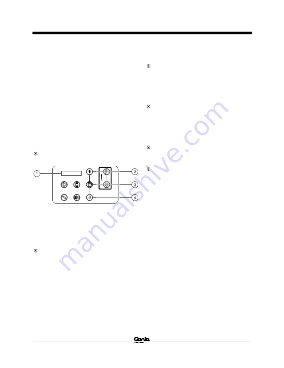
1 diagnostic display
2 blue platform up button
3 lift function enable button
4 yellow platform down button
3 Use the yellow platform down arrow to scroll
to select options.
Result: SELECT OPTIONS is showing in the
diagnostic display window. The ECM is now in
programming mode.
4 Press the lift function enable button.
Result: DESCENT DELAY is showing in the
diagnostic display window.
5 Press the lift function enable button to
deactivate the descent delay option.
6 Use the yellow platform down arrow to scroll
to overload.
Result: OVERLOAD ON is showing in the
diagnostic display window.
7 Press the lift function enable button to
deactivate the overload option.
8 Use the yellow platform down arrow to scroll
to return to the main menu.
Result: RETURN TO MAIN MENU is showing
in the diagnostic display window.
9 Press the lift function enable button.
Result: SELECT OPTIONS is showing in the
diagnostic display window.
10 Push in the ground controls red Emergency
Stop button to the off position.
11 Pull out the red Emergency Stop button to the
on position at the ground controls.
12 Start the engine from the ground controls.
13 Raise the platform approximately 10 feet /
3 m.
14 Lift the safety arm and move it to the center of
the linkage and rotate to a vertical position.
15 Lower the platform onto the safety arm. Push
in the red Emergency Stop button to the off
position.
Summary of Contents for GS-2669 IC
Page 141: ...May 2022 Service and Repair Manual 127 GM 998L Engine Wire Harness...
Page 144: ...Service and Repair Manual May 2022 130 Control Panel Circuit Diagram...
Page 145: ...May 2022 Service and Repair Manual 131 Electrical Schematic GS 69 RT GM 998L Models ANSI CSA...
Page 148: ...Service and Repair Manual May 2022 134 Electrical Schematic GS 69 RT GM 998L Models ANSI CSA...
Page 149: ...May 2022 Service and Repair Manual 135 Electrical Schematic GS 69 RT GM 998L Models ANSI CSA...
Page 152: ...Service and Repair Manual May 2022 138 Electrical Schematic GS 69 RT Diesel Models ANSI CSA...
Page 153: ...May 2022 Service and Repair Manual 139 Electrical Schematic GS 69 RT Diesel Models ANSI CSA...
Page 156: ...Service and Repair Manual May 2022 142 Electrical Schematic GS 69 RT Diesel Models ANSI CSA...
Page 157: ...May 2022 Service and Repair Manual 143 Electrical Schematic GS 69 RT GM 998L Models AS CE...
Page 160: ...Service and Repair Manual May 2022 146 Electrical Schematic GS 69 RT GM 998L Models AS CE...
Page 161: ...May 2022 Service and Repair Manual 147 Electrical Schematic GS 69 RT GM 998L Models AS CE...
Page 164: ...Service and Repair Manual May 2022 150 Electrical Schematic GS 69 RT Diesel Models AS CE...
Page 165: ...May 2022 Service and Repair Manual 151 Electrical Schematic GS 69 RT Diesel Models AS CE...
Page 168: ...Service and Repair Manual May 2022 154 Electrical Schematic GS 69 RT Diesel Models AS CE...
Page 169: ...May 2022 Service and Repair Manual 155 Hydraulic Schematic GS 69 RT...
Page 171: ......


