background image

Service and Repair Manual


May 2022


Kubota WG972 Engine 


42 

GS

-2669 RT • GS

-3369 RT • GS

-4069 RT 

Part No. 1306516GT 


5-6 

Engine RPM 

How to Adjust the RPM 

Note: The on-board self diagnostics incorporate a 

built-in engine tachometer. The engine rpm is 

displayed on the diagnostic display when the start 

button is held to the start position with the engine 

running. 
Note: Perform this procedure in gasoline mode 

with the engine at normal operating temperature. 
1  Start the engine from the ground controls. 
2  Hold the start toggle switch to the start 

position and check the engine RPM on the 

diagnostic display. Refer to Specifications, 

Engine Specifications

. Proceed to step 9 if the 

low idle is correct. 

3  To correct the low idle speed, Loosen the 

core clamp screw so the cable moves freely. 


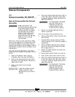
1  core clamp screw 
2  throttle lever 
3  low idle adjustment screw 
4  lock nut 
5  high idle adjustment nut 
6  high idle solenoid 


Summary of Contents for GS-2669 IC

Page 1: ...69F 18000 from GS69M 101 This manual includes Repair procedures Fault Codes Electrical and Hydraulic Schematics GS 3369 IC GS 4069 IC For detailed maintenance procedures refer to the appropriate Maint...

Page 2: ...ine Design Life Unrestricted with proper operation inspection and scheduled maintenance Technical Publications Genie has endeavored to deliver the highest degree of accuracy possible However continuou...

Page 3: ...e Section Procedure Page Description A 5 2021 Initial Release A1 5 2022 Fault Codes Platform Overload Fault Codes Reference Examples Electronic Version Click on any content or procedure in the Table o...

Page 4: ...6GT Revision History continued Revision Date Section Procedure Page Description Reference Examples Electronic Version Click on any content or procedure in the Table of Contents to view the update Sect...

Page 5: ...and Repair Manual Introduction Part No 1306516GT GS 2669 RT GS 3369 RT GS 4069 RT v Serial Number Legend 1 Model 2 Facility code 3 Sequence number 4 Serial label located inside cover 5 Serial number s...

Page 6: ...in the operator s manual are also safety hazards when maintenance and repair procedures are performed Do not modify or alter a MEWP without prior written permission from the manufacturer Do Not Perfo...

Page 7: ...tential crushing hazards such as moving parts free swinging or unsecured components when lifting or placing loads Always wear approved steel toed shoes Workplace Safety Any person working on or around...

Page 8: ...ral Safety Rules vi Section 2 Specifications 1 Machine Specifications 1 Performance Specifications 2 Hydraulic Oil Specifications 2 Hydraulic Component Specifications 6 Manifold Component Specificatio...

Page 9: ...Controls 16 1 1 Circuit Board 16 Platform Components 17 2 1 Platform 17 2 2 Platform Extension Deck 18 Scissor Components 20 3 1 Scissor Assembly GS 2669 RT 21 3 2 Scissor Assembly GS 3369 RT 24 3 3 S...

Page 10: ...ure Switches 39 4 6 How to Repair the Kubota D1105 Engine 40 Kubota WG972 Engine 41 5 1 Timing Adjustment 41 5 2 Carburetor Adjustment 41 5 3 Choke Adjustment 41 5 4 Flex Plate 41 5 5 Coolant Temperat...

Page 11: ...ion Speed Tuning 48 How to Determine the Revision Level 49 How to Adjust the Stowed Drive Speed 49 How to Adjust the High Torque Drive Speed 50 How to Adjust the Raised Drive Speed 51 How to Adjust th...

Page 12: ...Adjust the Oscillate Relief Valve 67 How to Adjust the Platform Up Relief Valve Models with Platform Overload 68 10 3 Outrigger Manifold Components 71 10 4 Traction Manifold Components View 1 72 10 4...

Page 13: ...Non steer Axle Components 88 13 1 Drive Motor Brake Assembly 88 13 2 Drive Hub 89 Outrigger Components 90 14 1 Outrigger Cylinder 90 Platform Overload Components 91 How to Calibrate the Platform Overl...

Page 14: ...Harness 128 Control Panel Circuit Diagram 129 Electrical Schematics ANSI and CSA Models 131 Electrical Schematic GS 69 RT ANSI CSA GM 998L Models 132 Electrical Schematic GS 69 RT ANSI CSA GM 998L Mod...

Page 15: ...nut torque dry Front 90 ft lbs 122 Nm Lug nut torque lubricated Front 68 ft lbs 92 Nm Wheel lugs non steer end 9 5 8 18 Lug nut torque dry Rear 170 ft lbs 230 Nm Lug nut torque lubricated Rear 130 ft...

Page 16: ...ximum protection to hydraulic systems have the ability to perform over a wide temperature range and the viscosity index should exceed 140 They should provide excellent antiwear oxidation prevention co...

Page 17: ...above 120 F 49 C Hydraulic Fluid Temperature Range Ambient air temperature 1 Chevron hydraulic oil 5606A 2 Petro Canada Environ MV 46 3 UCON Hydrolube HP 5046D 4 Chevron Rando HD premium oil MV Chevro...

Page 18: ...ating system is used Continued use of Chevron 5606A hydraulic fluid or equivalent when ambient temperatures are consistently above 32 F 0 C may result in component damage Petro Canada Environ MV 46 Fl...

Page 19: ...2669 RT GS 3369 RT GS 4069 RT 5 UCON Hydrolube HP 5046 Fluid Properties ISO Grade 46 Viscosity index 192 Kinematic Viscosity cSt 149 F 65 C cSt 104 F 40 C cSt 0 F 18 C 22 46 1300 Flash point None Pou...

Page 20: ...ift relief valve pressure GS 4069 RT 2850 psi 197 bar Oscillate relief valve pressure 3300 psi 228 bar Steer flow regulator 2 gpm 7 6 L min Lift Outrigger flow regulator 6 gpm 23 L min Oscillate flow...

Page 21: ...g Chassis assembly GS 2669 4960 lbs 2250 kg Chassis assembly GS 3369 4960 lbs 2250 kg Chassis assembly GS 4069 6794 lbs 3082 kg GM Engine Models 998L Low idle 1100 rpm 36 6 Hz High idle 3000 rpm 100 H...

Page 22: ...liters Oil viscosity requirements 22 F to 86 F 30 C to 30 C 5W 30 synthetic 4 F to 90 F 20 C to 32 C 10W 40 Above 23 F 5 C 20W 50 Unit ships with 15W 40 Extreme operating temperatures may require the...

Page 23: ...es may require the use of alternative engine oils For oil requirements refer to the Engine Operator Manual for your engine Fuel Pump Fuel pressure static 2 84 psi 0 19 bar Fuel flow rate 0 125 gpm 0 4...

Page 24: ...bar Oil capacity including filter 4 6 quarts 4 4 liters Oil viscosity requirements Below 86 F 30 C 5W 20 4 F to 104 F 20 C to 40 C 10W 30 Above 14 F 10 C 15W 40 Unit ships with 15W 40 Extreme operati...

Page 25: ...1 1 2 8 3 4 16 1 1 2 10 7 8 14 1 1 2 12 1 1 16 12 1 1 4 16 1 5 16 12 1 20 1 5 8 12 1 24 1 7 8 12 1 SAE O ring Boss Port tube fitting installed into Aluminum all types SAE Dash Size Torque 4 14 ft lbs...

Page 26: ...is seated and retained properly 4 Position the tube and nut squarely on the face seal end of the fitting and tighten the nut finger tight 5 Tighten the nut or fitting to the appropriate torque Refer t...

Page 27: ...e correct number of flats for the proper tightening position Note The marks indicate the correct tightening positions have been determined Use the second mark on the body hex fitting to properly tight...

Page 28: ...he appropriate operator s manual on your machine Be sure that all necessary tools and parts are available and ready for use Use only Genie approved replacement parts Read each procedure completely and...

Page 29: ...ed to alert personnel to potential personal injury hazards Obey all safety messages that follow this symbol to avoid possible injury or death Indicates a imminently hazardous situation which if not av...

Page 30: ...Loosen the platform control box lid retaining fasteners Open the control box and secure the control box lid in a level position 3 Visually locate the circuit board mounted to the inside of the platfor...

Page 31: ...tform wiring 2 Remove the clamp that secures the platform controls cable to the platform 3 Disconnect the platform controls cable from the connector located under the platform 4 Remove the platform co...

Page 32: ...ting it Crushing hazard The platform will become unbalanced and fall it not properly supported Note Note the position of the slider blocks before the platform is removed so that when the platform is i...

Page 33: ...xtension 7 Carefully slide the platform extension out until the platform extension makes contact with the carriage on the forklift 8 Secure the platform extension deck railings to the carriage of the...

Page 34: ...enter pivot pin Qty 2 6 Number 2 pivot pin steer end 7 Number 1 center pivot pin Qty 2 ANSI CSA 8 Number 1 center pivot pin Qty 1 AS CE 9 Number 1 inner arm Non steer End 10Chassis pivot 11Slider bloc...

Page 35: ...from the linkage assembly Component damage hazard Cables can be damaged if they are kinked or pinched 4 Using a suitable supporting device attach a strap to the rod end of the lift cylinder Do not app...

Page 36: ...inner arm Make the chains tight but do not apply lifting pressure Crushing hazard The linkage assembly could become unbalanced and fall if not properly supported when removed from the machine 20 Remov...

Page 37: ...er pivot pin Qty 2 8 Number 2 pivot pin steer end 9 Number 1 outer arm 10Number 1 center pivot pin Qty 2 ANSI CSA 11Number 1 center pivot pin Qty 1 AS CE 12Number 1 inner arm Non steer End 13Chassis p...

Page 38: ...the linkage assembly Component damage hazard Cables and hoses can be damaged if they are kinked or pinched 4 Using an overhead supporting device attach a 4 hook sling chain to the ends of the number 4...

Page 39: ...lace it on a structure capable of supporting it 20 Tag and disconnect the harness from the lift cylinder valve block 21 Tag and disconnect the hydraulic hoses from the lift cylinder Plug the hoses and...

Page 40: ...ht but do not apply lifting pressure Crushing hazard The linkage assembly could become unbalanced and fall if not properly supported when removed from the machine 2 Remove the retaining fasteners from...

Page 41: ...center pivot pin Qty 2 12Number 2 pivot pin steer end 13Number 1 center pivot pin Qty 2 ANSI CSA OR Number 1 center pivot pin Qty 1 AS CE 14Number 1 inner arm 15Chassis pivot Non steer End 16Slider bl...

Page 42: ...linkage assembly Component damage hazard Cables and hoses can be damaged if they are kinked or pinched 4 Using an overhead supporting device attach a 4 hook sling chain to the ends of the number 4 inn...

Page 43: ...attach a strap to the rod end of the lower lift cylinder Do not apply pressure 21 Remove the lower cylinder rod end pivot pin retaining fasteners 22 Using a soft metal drift remove the pivot pin 23 L...

Page 44: ...ard The linkage assembly could become unbalanced and fall if not properly supported when removed from the machine 36 Remove the two carriage bolts that secure the inner arm and chassis pivot to the st...

Page 45: ...g device to the ladder at the non steer end of the machine Support the ladder Do not apply lifting pressure 2 Remove the fasteners securing the ladder to the chassis Remove the ladder from the machine...

Page 46: ...ide 7 Remove the slider feet by sliding them out of the slider channel 8 Remove the upper and lower wear pads and discard 9 Using a hard rubber mallet secure the upper and lower wear pads to the slide...

Page 47: ...is procedure without these skills and tools could result in death or serious injury and significant component damage Dealer service is strongly recommended Note When removing a hose assembly or fittin...

Page 48: ...ended Note When removing a hose assembly or fitting the O ring if equipped on the fitting and or hose end must be replaced All connections must be torqued to specification during installation Refer to...

Page 49: ...if excessive force is applied Do not continue to lower the platform after the safety arm makes contact with the cross tube 4 Disconnect the height angle sensor from the main harness 5 Remove the retai...

Page 50: ...ing is different than 1 remove the wire and connector plate from the three individual glow plugs Then one glow plug at a time measure the resistance between the glow plug and ground Result The resista...

Page 51: ...djustment screw clockwise to increase the rpm or counterclockwise to decrease the rpm Tighten the lock nut and recheck the rpm 1 high idle solenoid 2 low idle adjustment screw 3 lock nut 4 high idle a...

Page 52: ...kinked or pinched 4 Remove the flex plate mounting fasteners Remove the flex plate from the flywheel How to I nstall t he Flex Plat e How to Install the Flex Plate 1 Install the flex plate onto the fl...

Page 53: ...s open at approximately 7 psi 0 48 bar If the oil pressure drops below the switch point the contacts open and the engine will shut off to prevent damage A low oil pressure indicator light at the groun...

Page 54: ...9 RT Part No 1306516GT 4 6 How to Repair the Kubota D1105 Engine Repair procedures and additional engine information are available in the Kubota Operator s and Workshop Manuals Kubota D1105 Operator s...

Page 55: ...r Adjustment The carburetor cannot be adjusted The carburetor mixture screws are factory sealed with tamper resistant caps installed by the manufacturer If service or repair is needed contact your loc...

Page 56: ...nning Note Perform this procedure in gasoline mode with the engine at normal operating temperature 1 Start the engine from the ground controls 2 Hold the start toggle switch to the start position and...

Page 57: ...the engine idle control button to high idle rabbit symbol from the ground controls 10 Hold the start toggle switch to the start position and check the engine RPM on the diagnostic display Refer to Sp...

Page 58: ...switch point the switch contacts close and the engine will shut off to prevent damage The engine will not start until the temperature drops below the switch point The engine oil pressure switch is a...

Page 59: ...nstall the new switch Torque to 20 ft lbs 27 Nm Oil Pressure switch Install the new switch Torque to 88 in lbs 10 Nm Note Always use pipe thread sealant when installing a new switch 6 4 Engine RPM How...

Page 60: ...loosen the yoke lock nut on the high idle solenoid then turn the high idle adjustment nut and solenoid boot counterclockwise to increase the rpm or clockwise to decrease the rpm Tighten the yoke lock...

Page 61: ...nd secure it from moving Component damage hazard Hoses can be damaged if they are kinked or pinched 4 Remove the flex plate mounting fasteners Remove the flex plate from the flywheel How to I nstall t...

Page 62: ...total ECM voltage output The speeds of the following machine functions may be adjusted to compensate for wear in the hydraulic pump and drive motors Stowed drive speed High torque drive speed Raised d...

Page 63: ...ow The ECM is now in programming mode 5 Press the lift function enable button 6 Use the yellow platform down arrow to scroll to max fwd high speed drive Result MAX FWD HIGH SPEED drive is showing in t...

Page 64: ...Use the yellow platform down arrow to scroll to max fwd high torque drive Result MAX FWD HIGH TORQUE DRIVE is showing in the diagnostic display window 7 Press the lift function enable button 8 Press...

Page 65: ...orm down arrow to scroll to max fwd raised drive speed Result MAX FWD RAISED DRIVE SPEED is showing in the diagnostic display window 7 Press the lift function enable button 8 Press the yellow platform...

Page 66: ...ition at the ground controls Result TUNE SPEEDS is showing in the diagnostic display window The ECM is now in programming mode 5 Press the lift function enable button 6 Use the yellow platform down ar...

Page 67: ...achine the flashing beacons operate continuously when the key switch is turned to ground or platform controls and both red Emergency Stop buttons are pulled out to the on position Generator When insta...

Page 68: ...option to function correctly the machine must be equipped with flashing beacons Note If the machine is not equipped with flashing beacons and this option is set to on the ECU will display a 4021 faul...

Page 69: ...o main menu is showing in the diagnostic display window 14 Press the lift function enable button Result SELECT OPTIONS is showing in the diagnostic display window 15 Push in the ground controls red Em...

Page 70: ...ers Tip over hazard The tilt level sensor must be installed with the Y on the level sensor base towards the steer end of the machine Failure to install the tilt level sensor as instructed will cause t...

Page 71: ...the machine approximately 4 inches 10 cm 17 Remove the blocks from under both wheels 18 Lower the machine and remove the jack 19 Center a lifting jack under the drive chassis at the engine side of th...

Page 72: ...ll and Calibrate the Level Sensor Tip over hazard Failure to install or calibrate the level sensor as instructed will compromise machine stability and cause the machine to tip over resulting in death...

Page 73: ...position at both ground and platform controls 8 Set a multimeter to read DC voltage Adjust the side to side axis 9 Without disconnecting the wire harness from the level sensor connect the negative le...

Page 74: ...rgency Stop button to the off position Confirm the side to side level sensor setting 20 Center a lifting jack under the drive chassis at the ground controls side of the machine 21 Raise the machine ap...

Page 75: ...level sensor must be replaced Repeat this procedure beginning with step 2 Note For reference only the output of the level sensor should be approximately 1 5V DC To confirm connect the positive lead of...

Page 76: ...ear the function manifold on the tank side of the machine 3 Start the engine from the platform controls 4 Steer the machine fully to the right or left and hold Note the pressure reading on the pressur...

Page 77: ...sed position or component damage will occur 1 Turn the key switch to ground controls and pull out the red Emergency Stop buttons to the on position at both platform and ground controls 2 Gasoline LPG...

Page 78: ...00 psi 241 3 bar FF System relief 20 25 ft lbs 27 34 Nm 7 Differential sensing valve 160 psi 11 bar FG Proportional valve circuit 20 25 ft lbs 27 34 Nm 8 Check valve FH Differential sensing circuit 12...

Page 79: ...May 2022 Service and Repair Manual Manifolds Part No 1306516GT GS 2669 RT GS 3369 RT GS 4069 RT 65...

Page 80: ...om the platform and place the controls near the function manifold on the hydraulic tank side of the machine 3 Start the engine from the platform controls 4 Steer the machine fully to the right or left...

Page 81: ...ontrols 4 Start the engine from the platform controls 5 Fully move the drive controller in either direction Note the pressure readings on the pressure gauge Refer to Specifications Hydraulic Component...

Page 82: ...diagnostic display window The ECM is now in programming mode 4 Press the lift function enable button Result DESCENT DELAY is showing in the diagnostic display window 5 Press the lift function enable b...

Page 83: ...gine from the ground controls 23 Press and hold the lift function enable button and press and hold the blue platform up button Allow the platform to raise completely then continue activating the lift...

Page 84: ...Pull out the red Emergency Stop button to the on position at the ground controls Result TUNE SPEEDS is showing in the diagnostic display window 37 Use the yellow platform down arrow to scroll to sele...

Page 85: ...S 3369 RT GS 4069 RT 71 10 3 Outrigger Manifold Components The outrigger manifold is located beneath the hose cover panel on top of the drive chassis Index No Description Schematic Item Function Torqu...

Page 86: ...n 4 way TE Drive forward reverse 20 25 ft lbs 27 34 Nm 6 Orifice 0 060 inch 1 5 mm TF Equalizes pressure on both sides of divider combiner valve 17 7 Flow divider combiner valve TG Controls flow to di...

Page 87: ...May 2022 Service and Repair Manual Manifolds Part No 1306516GT GS 2669 RT GS 3369 RT GS 4069 RT 73...

Page 88: ...mm TN Two speed circuit 15 Pressure reducing valve 250 psi 17 2 bar TO Two speed and brake circuit 25 30 ft lbs 34 40 Nm 16 Orifice 0 035 inch 9 mm TP Equalizes pressure on both sides of divider comb...

Page 89: ...May 2022 Service and Repair Manual Manifolds Part No 1306516GT GS 2669 RT GS 3369 RT GS 4069 RT 75...

Page 90: ...T 10 5 Generator Manifold Components The generator manifold is located above the function manifold Index No Description Schematic Item Function Torque 1 Proportional solenoid valve DA Generator speed...

Page 91: ...il to be tested 2 Test the coil resistance using a multimeter set to resistance Refer to the Valve Coil Resistance Specification table Result If the resistance is not within the adjusted specification...

Page 92: ...erminal on the coil Resistor 10 Genie part number 27287 Note The battery should read 9V DC or more when measured across the terminals 1 multimeter 2 9v DC battery 3 10 resistor 4 coil Note Dotted line...

Page 93: ...ch to ground controls 4 Press and hold both the blue platform up and yellow platform down buttons Pull out the red Emergency Stop button to the on position at the ground controls Result TUNE SPEEDS is...

Page 94: ...iner due to the possibility of fire 1 Remove the fuel filler cap from the tank 2 Using an approved hand operated pump drain the fuel tank into a suitable container Refer to Specifications Machine Spec...

Page 95: ...ulic tank cap 2 Remove the drain plug from the hydraulic tank and completely drain the tank into a container of suitable capacity Refer to Specifications Machine Specifications Bodily injury hazard Sp...

Page 96: ...e drive motor Cap the fittings on the drive motor Bodily injury hazard Spraying hydraulic oil can penetrate and burn skin Loosen hydraulic connections very slowly to allow the oil pressure to dissipat...

Page 97: ...e and Fitting Torque Specifications 1 Refer to Repair Procedure How to Remove the Yoke and Drive Motor 2 Remove the drive motor mounting fasteners Remove the drive motor from the yoke 12 2 Steer Cylin...

Page 98: ...ns 1 Tag disconnect and plug the hydraulic hoses from the oscillate cylinder Cap the fittings on the cylinder Bodily injury hazard Spraying hydraulic oil can penetrate and burn skin Loosen hydraulic c...

Page 99: ...wire from the oscillate right coil item B and set aside Refer to illustration 2 illustration 2 3 Tag and disconnect the connector with the blue wire from the steer right coil item C Connect it to the...

Page 100: ...C Refer to illustration 2 10 Disconnect the connector with the blue black wire from the oscillate left coil item A Connect it to the steer left coil item D Refer to illustration 2 11 Connect the conne...

Page 101: ...A2 and CR9 terminal 30 12V input power is sent to ECM U5 connector J2 A1 Oscillate Stowed Relays CR9 and CR10 When stowed on a flat level surface and the drive function is enabled the ECM sends 12V i...

Page 102: ...assembly Cap the fittings Bodily injury hazard Spraying hydraulic oil can penetrate and burn skin Loosen hydraulic connections very slowly to allow the oil pressure to dissipate gradually Do not allow...

Page 103: ...ve the drive motor brake assembly Refer to Repair Procedure 13 1 How to Remove a Drive Motor Brake Assembly 2 Center a lifting jack of ample capacity under the drive chassis at the non steer end of th...

Page 104: ...ng fasteners from the outside outrigger cover Remove the cover 5 Tag disconnect and plug the hydraulic hoses from the outrigger cylinder Cap the fittings on the cylinder Bodily injury hazard Spraying...

Page 105: ...lifting device place and secure the maximum rated load in the center of the platform deck Model Maximum rated load GS 2669 1500 lbs 680 kg GS 3369 1000 lbs 454 kg GS 4069 800 lbs 363 kg 3 Turn the key...

Page 106: ...p at predetermined points to gather data Continue holding the Function Enable and Platform Down buttons until the platform is fully stowed 13 When the platform is fully stowed momentarily activate the...

Page 107: ...t the red Emergency Stop button to the on position at the platform controls 2 Press and hold both the blue platform up and yellow platform down buttons Pull out the red Emergency Stop button to the on...

Page 108: ...larm is heard 4 Raise the platform until it stops 5 Push in the red Emergency Stop button to the off position 6 Measure the distance between the surface and the platform floor Model Measurement GS 266...

Page 109: ...perating instructions in the appropriate operator s manual on your machine Be sure that all necessary tools and test equipment are available and ready for use Read each appropriate fault code thorough...

Page 110: ...1306516GT About This Section When a malfunction is discovered the fault code charts in this section will help a service professional pinpoint the cause of the problem To use this section basic hand t...

Page 111: ...stic readout displays numerical codes that provide information about the machine operating status and about malfunctions The dot to the right of the numbers remain on when a fault code is displayed Th...

Page 112: ...T TURN SW FAULT Red Left turn switch fault Malfunctioning steer left microswitch Troubleshoot steer left microswitch 26 RIGHT TURN SW FAULT Red Right turn switch fault Malfunctioning steer right micro...

Page 113: ...vel enable button fault at platform controls Outriggers disabled Troubleshoot button OR replace printed circuit board at platform controls 3812 OSCILLATE LIMIT SWITCHES Red Value to high Voltage above...

Page 114: ...n inhibited Troubleshoot coil OR wiring 58 BRAKE COIL FAULT Red Brake release coil Y2 fault Brakes will not release Troubleshoot coil OR wiring 60 FORWARD 1 COIL FAULT Red Forward 1 coil Y6 fault Driv...

Page 115: ...g 82 RIGHT FRONT OTRG COIL FLT Red Right front outrigger coil Y36 fault Right front outrigger function inhibited Troubleshoot coil OR wiring 83 RIGHT REAR OTRG COIL FLT Red Right rear outrigger coil Y...

Page 116: ...Platform Overload Display 1 LCD screen 2 red LED The diagnostic readout displays numerical codes that provide information about height sensor pressure sensor and platform overload malfunctions The co...

Page 117: ...not reading consistent or correlated signals Check wiring Shorted to high or low Replace sensor 15 Value too low Output lower than normal Check wiring Check 5V supply voltage Check ground Open or shor...

Page 118: ...Shorted too high Replace sensor 15 Value too low Output lower than normal Check wiring Check 5V supply voltage Check ground Open or short circuit Replace sensor 16 Value at 0 V Output at 0 volts Chec...

Page 119: ...horted to high or low Replace sensor 15 Value too low Output lower than normal Check wiring Check 5V supply voltage Check ground Open or short circuit Replace sensor 16 Value at 0 V Output at 0 volts...

Page 120: ...SCON detect an internal safety fault Replace SCON 29 Software version mismatch Primary and secondary processors software do not match Update software Replace SCON 76 Platform Overload 23 Too high Pla...

Page 121: ...tic trouble code DTC is related to either an engine shutdown fault or an oxygen sensor fault the following statement applies If the machine is not serviced by a technician and the condition causing th...

Page 122: ...Injector 5 open or short to ground 655 5 DTC 122 TPS1 voltage low 51 4 DTC 274 Injector 5 coil shorted 655 6 DTC 123 TPS1 voltage high 51 3 DTC 276 Injector 6 open or short to ground 656 5 DTC 127 IAT...

Page 123: ...ow 520202 1 DTC 616 Start relay ground short 1321 4 DTC 1163 Adaptive learn NG high 520203 0 DTC 617 Start relay coil short to power 1321 3 DTC 1164 Adaptive learn NG low 520203 1 DTC 627 Fuel pump re...

Page 124: ...stage 2 442 0 DTC 1555 Water Intrusion Detection 520224 3 DTC 1419 ERWT1 voltage high 443 3 DTC 1556 AUX digital 3 low voltage 520224 4 DTC 1420 ERWT2 voltage high 444 3 DTC 1561 AUX analog Pull Down...

Page 125: ...short to power 920 3 DTC 2300 Spark coil 1 primary open or short to ground 1268 5 DTC 1644 MIL control ground short 1213 4 DTC 2301 Spark coil 1 primary shorted 1268 6 DTC 1645 MIL control short to po...

Page 126: ...ocessor internal fault 3221 1 DTC 8911 UEGO sense cell voltage low 3218 4 DTC 8902 UEGO heater supply high voltage 3222 3 DTC 8912 UEGO pump voltage at high drive limi 3217 3 DTC 8903 UEGO heater supp...

Page 127: ...obey the safety rules and operating instructions in the appropriate operator s manual on your machine Be sure that all necessary tools and test equipment are available and ready for use About This Se...

Page 128: ...ane select ground BN33 Platform up down enable ground BN34 Platform up ground BN35 Platform down ground BN91 Auxiliary platform down ground C Capacitor C1 10000 f CB Circuit breaker CB2 20 amp control...

Page 129: ...JC4 Drive Steer JC10 Platform up down Outriggers extend retract KS Key switch KS1 Key switch L LED or Light L12 Left front outrigger option platform L13 Right front outrigger option platform L14 Left...

Page 130: ...n enable platform SW6 Steer right left platform Item Description TB Terminal base Ground controls terminal strip TS Toggle switch TS18 Work light option U Electronic Component U3 Circuit board platfor...

Page 131: ...3369 RT GS 4069 RT 117 Color Description BL Blue BK Black BR Brown GR Green OR Orange PP Purple RD Red WH White YL Yellow BL RD Blue Red BL WH Blue White BK RD Black Red OR WH Orange White RD BK Red...

Page 132: ...t FD 2 position 3 way directional valve platform up down FE Relief valve Platform up circuit FF Relief valve Main system FG Differential sensing valve meters flow to functions FH Check valve different...

Page 133: ...equalizes drive pressure at non steer end TG Combiner Divider valve controls flow to front and rear drive motors TH Combiner Divider valve Controls flow to steer end drive motors TI Orifice equalizes...

Page 134: ...LED Fuse with amperage Circuit breaker with amperage Connection no terminal Circuits crossing no connection Quick disconnect terminal Level sensor without outriggers Power relay Coil solenoid or relay...

Page 135: ...le valve Solenoid operated 3 position 4 way directional valve Solenoid operated 3 position 5 way directional valve Solenoid operated 2 position 3 way directional valve Solenoid operated 2 position 2 w...

Page 136: ...No 1306516GT 1 left rear outrigger limit switch LS14 2 left axle oscillate limit switches LSA10S and LSA10SS 3 right rear outrigger limit switch LS15 4 right axle oscillate limit switches LSA20S and L...

Page 137: ...May 2022 Service and Repair Manual Electronic Control Module Pin Out Legend Part No 1306516GT GS 2669 RT GS 3369 RT GS 4069 RT 123 Electronic Control Unit Pin Numbering 36 pin connector...

Page 138: ...input C9 Engine water temp SW1 input C10 Not used C11 Fuel pump output Gas LPG models C12 Oscillate fault detector input J2 Connector A1 Down limit height TB 43 input A2 Down limit height TB 26 input...

Page 139: ...5 CR72 CR9 CR4 CR10 C 2 R CR5 CR1 CR71 CR62 C1 1 2 3 4 5 6 7 8 9 10 11 12 13 14 15 16 17 18 19 20 21 22 23 24 25 26 27 28 29 30 31 32 33 34 35 36 37 38 39 40 4142 43 44 45 4647 48 49 50 5152 53 54 55...

Page 140: ...ics 126 GS 2669 RT GS 3369 RT GS 4069 RT Part No 1306516GT 1 Power Relay 7 Fuel Pump Fuse 15A 2 Fuel Pump Relay 8 DEPR Fuse 5A 3 Starter Relay 9 ECM Fuse 10A 4 Alternator Fuse 60A 10 Ignition Fuse 20A...

Page 141: ...May 2022 Service and Repair Manual 127 GM 998L Engine Wire Harness...

Page 142: ...Service and Repair Manual May 2022 128 GS 2669 RT GS 3369 RT GS 4069 RT Part No 1306516GT GM 998L Engine Wire Harness...

Page 143: ...LEVEL SENSOR GROUND S8 LEVEL SENSOR PITCH KS1 KEY SWITCH S7 LEVEL SWITCH AUX DOWN IN AUX DOWN OUT LS6 LS6B DLS CHANNEL 2 TB 9 TB 8 TB 41 TB 49 TB 48 TB 47 TB 46 TB 56 TB 55 TB 54 TB 30 TB 52 TB 51 TB...

Page 144: ...Service and Repair Manual May 2022 130 Control Panel Circuit Diagram...

Page 145: ...May 2022 Service and Repair Manual 131 Electrical Schematic GS 69 RT GM 998L Models ANSI CSA...

Page 146: ...COIL Y98 HI SPEED BYPASS H2 HORN J2 B11 J2 B8 J2 C12 B1 12 VOLT BATTERY CHASSIS PLAT J1 A7 Y97 FRONT MOTOR FREE WHEEL Y96 FRONT MOTORS ISOLATE J1 A11 J1 A10 J2 C7 J1 C7 FB1 BEACON 3 J2 C11 J2 B7 J2 A...

Page 147: ...May 2022 Service and Repair Manual Part No 1306516GT GS 2669 RT GS 3369 RT GS 4069 RT 133 Electrical Schematic GS 69 RT GM 998L Models ANSI CSA...

Page 148: ...Service and Repair Manual May 2022 134 Electrical Schematic GS 69 RT GM 998L Models ANSI CSA...

Page 149: ...May 2022 Service and Repair Manual 135 Electrical Schematic GS 69 RT GM 998L Models ANSI CSA...

Page 150: ...SENSOR POWER 9 SENSOR GROUND 12 ANGLE SENSOR HIGH 13 ANGLE SENSOR LOW 18 PRESSURE SENSOR HIGH 19 PRESSURE SENSOR LOW 33 STOP UP INTERUPT 34 STOP DOWN INTERUPT 23 UP VALVE FROM ECU 24 DOWN VALUE FROM...

Page 151: ...B1 J2 C11 5 Y29 GENERATOR PR2 STARTER RELAY D1 ALTERNATOR G6 ENGINE HOURMETER Y9 PROPORTIONAL FLOW J1 A12 J2 A3 J2 A4 J2 A5 J1 A6 J1 A4 J1 A5 Y6 DRIVE FORWARD Y5 DRIVE REVERSE Y27 2 SPEED COIL Y98 HI...

Page 152: ...Service and Repair Manual May 2022 138 Electrical Schematic GS 69 RT Diesel Models ANSI CSA...

Page 153: ...May 2022 Service and Repair Manual 139 Electrical Schematic GS 69 RT Diesel Models ANSI CSA...

Page 154: ...Service and Repair Manual May 2022 140 GS 2669 RT GS 3369 RT GS 4069 RT Part No 1306516GT Electrical Schematic GS 69 RT Diesel Models ANSI CSA...

Page 155: ...SENSOR POWER 9 SENSOR GROUND 12 ANGLE SENSOR HIGH 13 ANGLE SENSOR LOW 18 PRESSURE SENSOR HIGH 19 PRESSURE SENSOR LOW 33 STOP UP INTERUPT 34 STOP DOWN INTERUPT 23 UP VALVE FROM ECU 24 DOWN VALUE FROM E...

Page 156: ...Service and Repair Manual May 2022 142 Electrical Schematic GS 69 RT Diesel Models ANSI CSA...

Page 157: ...May 2022 Service and Repair Manual 143 Electrical Schematic GS 69 RT GM 998L Models AS CE...

Page 158: ...COIL Y98 HI SPEED BYPASS H2 HORN J2 B11 J2 B8 J2 C12 B1 12 VOLT BATTERY CHASSIS PLAT J1 A7 Y97 FRONT MOTOR FREE WHEEL Y96 FRONT MOTORS ISOLATE J1 A11 J1 A10 J2 C7 J1 C7 FB1 BEACON 3 J2 C11 J2 B7 J2 A2...

Page 159: ...May 2022 Service and Repair Manual Part No 1306516GT GS 2669 RT GS 3369 RT GS 4069 RT 145 Electrical Schematic GS 69 RT GM 998L Models AS CE...

Page 160: ...Service and Repair Manual May 2022 146 Electrical Schematic GS 69 RT GM 998L Models AS CE...

Page 161: ...May 2022 Service and Repair Manual 147 Electrical Schematic GS 69 RT GM 998L Models AS CE...

Page 162: ...ENSOR POWER 9 SENSOR GROUND 12 ANGLE SENSOR HIGH 13 ANGLE SENSOR LOW 18 PRESSURE SENSOR HIGH 19 PRESSURE SENSOR LOW 33 STOP UP INTERUPT 34 STOP DOWN INTERUPT 23 UP VALVE FROM ECU 24 DOWN VALUE FROM EC...

Page 163: ...B1 J2 C11 Y29 GENERATOR PR2 STARTER RELAY D1 ALTERNATOR G6 ENGINE HOURMETER Y9 PROPORTIONAL FLOW J1 A12 J2 A3 J2 A4 J2 A5 J1 A6 J1 A4 J1 A5 Y6 DRIVE FORWARD Y5 DRIVE REVERSE Y27 2 SPEED COIL Y98 HI S...

Page 164: ...Service and Repair Manual May 2022 150 Electrical Schematic GS 69 RT Diesel Models AS CE...

Page 165: ...May 2022 Service and Repair Manual 151 Electrical Schematic GS 69 RT Diesel Models AS CE...

Page 166: ...Service and Repair Manual May 2022 152 GS 2669 RT GS 3369 RT GS 4069 RT Part No 1306516GT Electrical Schematic GS 69 RT Diesel Models AS CE...

Page 167: ...ENSOR POWER 9 SENSOR GROUND 12 ANGLE SENSOR HIGH 13 ANGLE SENSOR LOW 18 PRESSURE SENSOR HIGH 19 PRESSURE SENSOR LOW 33 STOP UP INTERUPT 34 STOP DOWN INTERUPT 23 UP VALVE FROM ECU 24 DOWN VALUE FROM EC...

Page 168: ...Service and Repair Manual May 2022 154 Electrical Schematic GS 69 RT Diesel Models AS CE...

Page 169: ...May 2022 Service and Repair Manual 155 Hydraulic Schematic GS 69 RT...

Page 170: ...SI 037 037 OUT SV14 SV15 3100 2900 GS 2669 GS 3369 MODEL PRESSURE GS 4069 2850 RV6 RV5 160 PSI 3300 CV2 6 GPM FR2 SV3 Y8 Y95 SV6 1 GPM 1 RV2 CV1 PS1 Y9 SP1 PS3 FR1 FR3 SV1 RV1 SV5 SV4 2 GPM 850 Y94 Y9...

Page 171: ......

Reviews: