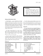
Brake--Speed sensor of front wheel
Speed sensor of front wheel
Change
Hint: the process for changing right side is same as the
left side.
1. Disassemble front wheels.
2. Disassemble gasket of left front wing.
3. Disassemble speed sensor of left front wheel.
(a) Disassemble resinous clamp and speed sensor wiring har-
ness from fixing clamp of automobile body.
(b) Disassemble the sensor joint.
(c) Disassemble two bolts of fixing clamp of sensor wiring har-
ness from automobile body and absorber.
(d) Disassemble bolt and left front sensor.
Note: do not attach any sundries on top of sensor.
4. Assemble speed sensor of left front wheel.
(a) Use bolt to assemble left front sensor.
Torque: 8.0 N
⋅⋅⋅⋅⋅
m
Note: do not attach any sundries on top of sensor.
(b) Use two bolts to assemble fixing clamp of sensor wiring
harness on automobile body and absorber.
Bolt A: 9.0 N
⋅⋅⋅⋅⋅
m
Bolt B: 29 N
⋅⋅⋅⋅⋅
m
(c) Connect the joint of speed sensor.
(d) Connect resinous clamp and speed sensor wiring harness
on automobile body and fixing clamp.
5. Assemble gasket of left front wheel wing.
6. Assemble front wheels.
Torque: 103
±±±±±
10 N
⋅⋅⋅⋅⋅
m
7. Check the signal of ABS speed sensor.
151
Summary of Contents for FC
Page 1: ......
Page 2: ......
Page 302: ...Light Side turning light Side turning light Components Side turning light 291 ...
Page 409: ...Electric glass lifter Electrical schematic diagram Electric glass lifter 398 ...
Page 412: ...Electric rearview mirror Electrical schematic diagram Electric rearview mirror 401 ...
Page 413: ...Reversing radar system Electrical schematic diagram Reversing radar system 402 ...
Page 414: ...Safety airbag system Electrical schematic diagram Safety airbag system 403 ...
Page 418: ...Combination instrument Electrical schematic diagram Combination instrument 407 ...


