CHAPTER 2: GETTING STARTED
GETTING STARTED
MULTINET4 MULTI-PORT SERIAL SERVER & MANAGED SWITCH – INSTRUCTION MANUAL
2–13
Z
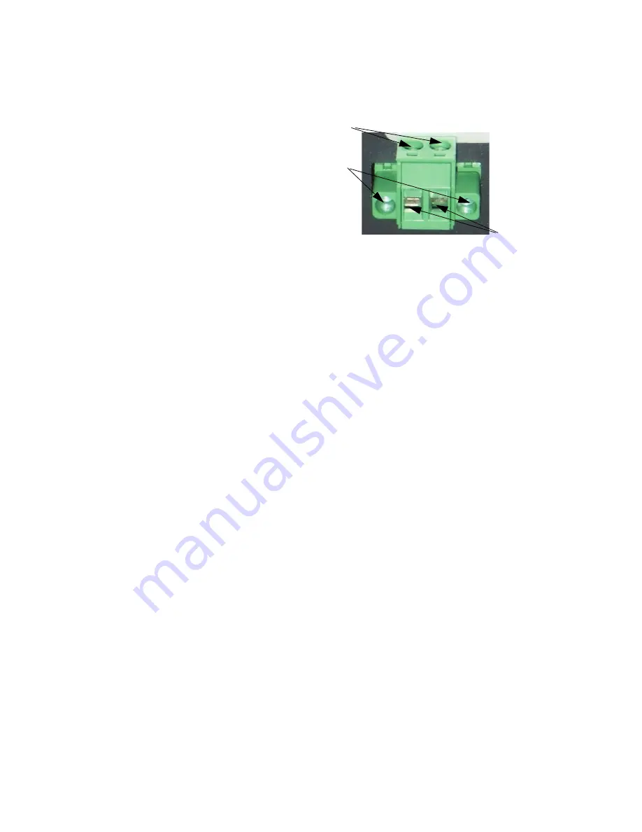
Re-insert the plug into the power connector and secure the two
captive mounting screws.
FIGURE 2–11: Non-Polarized Power Input
2.3.3
Connecting to the Console Port and the Alarm Port
2.3.3.1 Console Port
Use a DB9 null-modem cable or a DB9-to-USB null-modem cable, to connect the Multinet4
console port (the RS232 port) to the PC.
2.3.3.2 Alarm Port
Resevered for future use.
2.3.4
Connecting Network Cables
There are three types of connections that can be made to the Multinet4. They are serial,
Ethernet copper, and Ethernet fiber optic. The following sections describe each type of
connection separately.
2.3.4.1 Connecting Serial Cables
This procedure assumes that one end of the Serial device cable is already attached to the
end unit. Be aware of the serial port numbering scheme when installing the cables see (see
section1.3: Pinouts
). The ports are configured in software later on and if a device is
accidentally connected to the wrong port it will be difficult to detect.
Connect cables to the serial ports as described below (A 3/32” slotted screwdriver is
required.):
1.
Remove the plug portion of the phoenix connector by loosening the two captive
mounting screws.
2.
Strip back 1/4" off the insulation of the wires.
3.
Loosen saddle screws and insert each conductor firmly into a terminal hole of the
plug
4.
Visually inspect that no strands of wire are straying out of the hole, potentially
shorting to ground or the other conductor.
saddle screws
captive mounting screws
terminal holes


