GE Multilin 889 Instruction Manual Download Page 249

CHAPTER 4: SETPOINTS

PROTECTION

889 GENERATOR PROTECTION SYSTEM – INSTRUCTION MANUAL

4–119

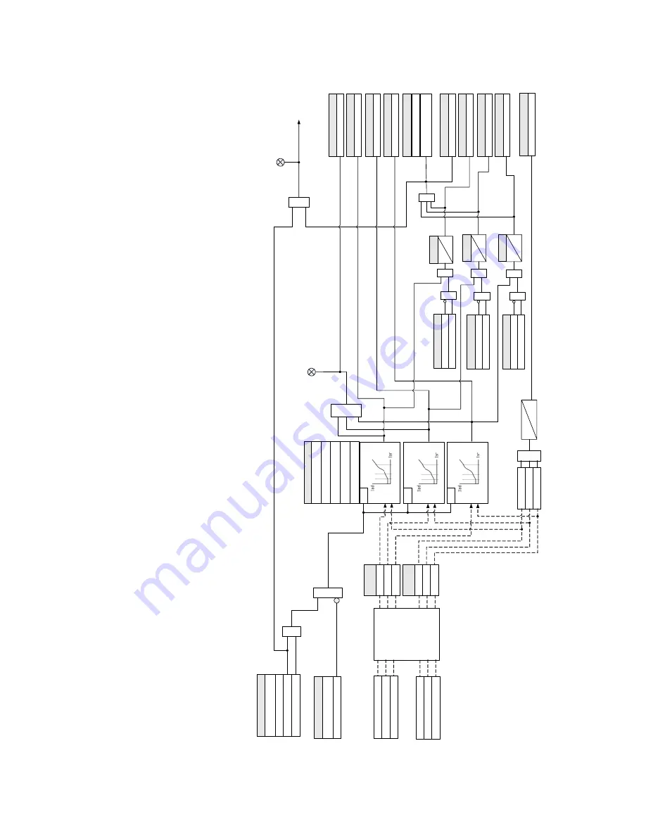
Figure 4-39: Percent Differential logic diagram

SETPOINT

Phase

A

 current 

(I

a)

SETPOINT

FUNCTION

Disabled

T

rip

Pickup

AND

Phase B current 

(I

b)

Phase C current 

(I

c)

RUN

TRIP

LED

:

PICKUP

OR

Neutral side currents 

(I

ns

)

(K

1

-CT

)

Bank

SETPOINT

BLOCK

Of

f

=

0

OR

AND

Configurable

SETPOINTS

Output Relays

Do Not Operate

,

Operate

LED

:

TRIP

Percent Dif

f PKP

 C

FlexLogic Operands

Phase

A

 current 

(I

a

)

Phase B current 

(I

b

)

Phase C current 

(I

c)

T

erminal side currents 

(I

ts

)

(J

1

-CT

)

Bank

I

ar

I

br

I

cr

Restraint

Phasors

I

ad

I

bd

I

cd

Dif

ferential

Phasors

Break

2

Slope

2

Slope

1

Break

1

Percent Dif

f PKP

A

FlexLogic Operands

Percent Dif

f PKP

FlexLogic Operands

Percent Dif

f PKP

 B

FlexLogic Operands

Percent Dif

f OP

 C

FlexLogic Operands

Percent Dif

f OP

A

FlexLogic Operands

Percent Dif

f OP

FlexLogic Operands

Percent Dif

f OP

 B

FlexLogic Operands

Percent Dif

f Sat C

FlexLogic Operands

Percent Dif

f Dir C

OR

AND

Percent Dif

f Sat B

FlexLogic Operands

Percent Dif

f Dir B

OR

AND

Percent Dif

f Sat 

A

FlexLogic Operands

Percent Dif

f Dir 

A

OR

AND

OR

|I

d

|=

|I

ts

-I

ns

|

|I

r

|

=

MAX

{|

I

ts

|, |

I

ns

|}

I ad

>

(0

.

5

x

 PKP

)

I bd

>

(0

.

5

x

 PKP

)

I cd

>

(0

.

5

x

 PKP

)

OR

Percent Dif

f W

arn

FlexLogic Operands

10

s

0s

RUN

RUN

T

pkp

0

T

pkp

0

T

pkp

0

SETPOINT

SETPOINT

SETPOINT

894147.

CDR

Summary of Contents for Multilin 889

Page 1: ...Instruction manual Product version 2 0x GE publication code 1601 0320 A3 GEK 119652B 1601 0450 A3 889 Generator Protection System Generator Protection Control and Asset Management GE Grid Solutions ...

Page 2: ...tered trademarks of GE Multilin Inc The contents of this manual are the property of GE Multilin Inc This documentation is furnished on license and may not be reproduced in whole or in part without the permission of GE Multilin The content of this manual is for informational use only and is subject to change without notice Part number 1601 0320 A3 July 2017 Note May contain components with FCC ID X...

Page 3: ...nd Warnings 1 34 Must read Information 1 37 Storage 1 38 For Further Assistance 1 38 Repairs 1 38 2 INSTALLATION Mechanical Installation 2 1 Product Identification 2 1 Dimensions 2 2 Mounting 2 3 Standard Panel Mount 2 4 Depth Reducing Collar 2 5 Draw out Unit Withdrawal and Insertion 2 7 Removable Power Supply 2 8 Removable Magnetic Module 2 9 Arc Flash Sensor 2 10 Sensor Fiber Handling Storage 2...

Page 4: ...with Setpoints Setpoints Files 3 24 Engaging a Device 3 25 Entering Setpoints 3 25 File Support 3 26 Using Setpoints Files 3 26 Downloading Saving Setpoints Files 3 27 Adding Setpoints Files to the Environment 3 27 Creating a New Setpoints File 3 28 Upgrading Setpoints Files to a New Revision 3 29 Printing Setpoints 3 30 Loading Setpoints from a File 3 31 Uninstalling Files and Clearing Data 3 31 ...

Page 5: ... 52 Flex States 4 52 Front Panel 4 52 Programmable LEDs 4 53 Programmable Pushbuttons 4 54 Tab Pushbuttons 4 58 Annunciator 4 61 Display Properties 4 63 Default Screens 4 64 Home Screens 4 65 Resetting 4 66 Installation 4 66 System 4 68 Current Sensing 4 68 Voltage Sensing 4 69 Traditional VT 4 69 Power Sensing 4 70 Power System 4 71 Generator 4 72 Setup 4 72 Transformer 4 73 Windings 4 74 Breaker...

Page 6: ...ve Ground Time Overcurrent Protection 51SG 4 192 Sensitive Ground Instantaneous Overcurrent Protection 50SG 4 195 Sensitive Ground Directional Overcurrent Protection 67SG 4 198 Restricted Ground Earth Fault 87G 4 203 Negative Sequence Instantaneous Overcurrent Protection 50_2 4 208 Negative Sequence Directional Overcurrent Protection 67_2 4 211 Load Encroachment 4 215 Voltage Elements 4 218 Phase ...

Page 7: ...352 Virtual Input Control 4 355 Trip Bus 4 355 Breaker Failure 50BF 4 358 Setup 4 359 Initiate 4 361 Arc Flash Protection 4 363 Synchrocheck 25 4 365 VT Fuse Failure VTFF 4 370 FlexLogic 4 372 Timers 4 382 Non volatile Latches 4 383 FlexLogic Equation 4 384 Viewing FlexLogic Graphics 4 386 FlexElements 4 387 Testing 4 393 Simulation 4 394 Setup 4 394 Pre Fault 4 395 Fault 4 396 Post Fault 4 397 Te...

Page 8: ...requency OOB Accumulation 6 7 Stator Ground 3rd Harmonic 6 7 Impedance 6 8 Positive Sequence Impedance 6 8 Currents 6 8 Voltages 6 10 Frequency 6 12 Volts Per Hertz 6 12 Harmonics 1 Harmonics 4 6 13 Harmonic Detection 6 14 Synchrocheck 6 14 Power 6 15 Energy 6 16 Power Factor 6 17 Current Demand 1 6 17 Power Demand 6 18 Directional Power 6 18 Arc Flash 6 19 RTDs 6 19 RTD Maximums 6 20 Analog Input...

Page 9: ...lear Records 7 6 8 MAINTENANCE Environmental Health Report 8 2 General Maintenance 8 4 In service Maintenance 8 4 Out of service Maintenance 8 4 Unscheduled Maintenance System Interruption 8 4 A APPENDIX A Warranty A 1 Revision history A 1 Major Updates A 2 ...

Page 10: ...VIII 889 GENERATOR PROTECTION SYSTEM INSTRUCTION MANUAL ...

Page 11: ...log inputs outputs module allows for monitoring of generator excitation current vibration and other parameters These relays contain many innovative features To meet diverse utility standards and industry requirements these features have the flexibility to be programmed to meet specific user needs This flexibility will naturally make a piece of equipment difficult to learn To aid new users in getti...

Page 12: ...s line voltage or three phase currents The signals are passed through a low pass filter to prevent false zero crossings Frequency tracking utilizes the measured frequency to set the sampling rate for current and voltage which results in better accuracy for the Discrete Fourier Transform DFT algorithm for off nominal frequencies The main frequency tracking source uses three phase bus voltages The f...

Page 13: ... timer has expired The voltage and current protection elements use RMS current voltage or the magnitude of the phasor Figure 1 1 Single Line Diagram 894153A2 cdr 50G 87GD 51G 64TN 51V 51N 46 67_2 78 24 59P 27P 25 Metering Transient Recorder Event Recorder Trip Close 40 59N 81U 81O 27TN 59X 52 R 87G 50N 81R 50P G 49 EX 889 Generator Protection System Slot J1 Ph Bank Slot K1 Ph Bank Slot J2 Ph Bank ...

Page 14: ...K1 Ph Bank Slot J2 Ph Bank Slot J Ground Slot J Vx Slot J Vx R RTD 50 27 67G 59_2 40Q 50SG 51SG 67SG 32 Slot K Ground Sensitive or 50 0 025 50N 50P 50_2 50_2 38 76 dcmA 50OL 39 dcmA 47 50OFL 81A 49TOL VTFF 50BF Alternatives for connection 27X Trip Close 52 Monitoring Slot K2 Ph Bank 87O 67_2 67P 67N 894166A2 cdr 27TN Monitoring AFP LIGHT 51N ANSI Device Description 24 Volts per Hertz 25 Synchroche...

Page 15: ...estrained Time Overcurrent 55 Power Factor 59N Neutral Overvoltage 59P Phase Overvoltage 59X Auxiliary Overvoltage 59_2 Negative Sequence Overvoltage 64TN 100 Stator Ground using 3rd Harmonic Voltage Differential 67G Ground Directional Element 67N Neutral Directional Element 67P Phase Directional Element 67SG Sensitive Ground Directional Element 67_2 Negative Sequence Directional Element 76 Excita...

Page 16: ...ons Flexstates Generator Health Report IEC 61850 Communications Metering current voltage power PF energy frequency harmonics THD Modbus User Map Non volatile Latches OPC UA Communications Output Relays RTD Temperature Setpoint Groups 6 Trip Bus 6 Transient Recorder Oscillography Trip and Close Coil Monitoring User programmable LEDs User programmable Pushbuttons Virtual Inputs 32 Virtual Outputs 32...

Page 17: ...al Outputs Targets Motor Metering Records Events Transients Motor Start Records Breakers Dig Counters Clear Records Currents Voltages Frequency Harmonics Harmonic Detection Energy RTDs Data Logger Fault Reports Motor Start Statistics Current Demand Power Demand Learned Data Directional Power Arc Flash Arc Flash Testing PTP Status Clock Device Status Information Communications Flex States Last Trip...

Page 18: ...ons based on specific roles and individual user accounts configured on the AAA server At present the defined roles are Administrator Operator and Observer Strong encryption of all access and configuration network messages between the EnerVista software and 889 devices using the Secure Shell SSH protocol the Advanced Encryption Standard AES and 128 bit keys in Galois Counter Mode GCM as specified i...

Page 19: ...le has read only access to all 889 settings This role allows concurrent access The Observer is the default role if no authentication has been done to the device This role can download settings files and records from the device Factory This is an internal non user accessible role used for manufacturing diagnostics The ability to enable or disable this role is a security setting that the Administrat...

Page 20: ...ital Inputs 4 Arc Flash Inputs A 2 Form A Vmon 3 Form C 7 Digital Inputs Low High voltage Int Ext Supply Faceplate M Basic Membrane Keypad G Standard Rugged Keypad Current Protection M Standard 38 RTD 1 39 AnIp 1 46 Gen Unbl 1 49 RTD 1 50 27 1 50OFL 1 50OL 1 50P 2 CT bank 50N 1 CT bank 50G 2 50SG 1 50_2 1 CT bank 51V 2 51N 2 51G 2 51SG 1 67N 1 67G 1 67SG 1 76 AnIp 1 87G 1 A Advanced Standard 67P 1...

Page 21: ...ed on the existing relay order code and additional requirements Navigate to https www gegridsolutions com multilin catalog 889 htm and click Buy Retrofit Kit for further information Accessories 18J0 0030 8 Series Depth Reducing Collar 1 3 8 18J0 0029 8 Series Depth Reducing Collar 3 8 Series Retrofit Kit 489 to 889 892800D3 PDF Wireless Communication N None W WiFi 802 11 Security B Basic A Advance...

Page 22: ...CT Dropout Level 97 to 98 of Pickup Level Accuracy For 0 1 to 0 2 x CT 0 2 of reading or 1 5 of rated whichever is greater For 0 2 x CT 1 5 of reading Operate Time 4 ms at 6 x Pickup at 60 Hz 5 ms at 6 x Pickup at 50 Hz 4 8 ms at 3 6 x Pickup at 60 Hz 4 10 ms at 3 6 x Pickup at 50 Hz DIRECTIONAL POWER 32 Measured Power 3 phase Number of Stages 2 Characteristic Angle 0º to 359º in steps of 1 Calibr...

Page 23: ...e alarm Trip Alarm Pickup Level 0 00 to 100 00 FLA in steps of 0 01 Constant K 0 00 to 100 00 in steps of 0 01 Maximum Time 0 to 1000 s in steps of 1 s Reset Time 0 00 to 1000 00 s in steps of 0 01 s Alarm Delay 0 00 to 600 00 s in steps of 0 01 s Pickup Accuracy 0 025 A or 3 of reading whichever is greater Operate Time 20 ms at 1 10 x pickup at 60 Hz Timing Accuracy 3 of operate time or 20 ms whi...

Page 24: ...Pickup Level 0 005 to 0 900 in steps of 0 001 Level Accuracy 0 02 pu Dropout Level 103 of Pickup for 0 333 Pickup 0 010 for 0 333 97 of 1 Pickup for 0 333 1 Pickup 0 010 for 0 333 Voltage Supervision Level 0 5 to 30 0 V in steps of 0 1 Supervision Level Accuracy 5 of reading for 1V up to 45 V secondary 0 07 V for 1V Supervision Dropout Level 97 of pickup for 7V Pickup 0 2V for 7V Pickup Time Delay...

Page 25: ... curve time to obtain the TOC operating time i e from fault inception until operation PHASE DIRECTIONAL OVERCURRENT 67P Relay Connection 90º Quadrature Quadrature Voltage ABC phase seq phase A Vbc phase B Vca phase C Vab ACB phase seq phase A Vcb phase B Vac phase C Vba Polarizing Voltage Threshold 0 050 to 3 000 x VT in steps of 0 001 x VT Current Sensitivity Threshold 0 05 x CT Characteristic An...

Page 26: ...g Operating Current Isg Level Sensing Ig Isg Characteristic Angle 90º to 90º in steps of 1 Limit Angle 40º to 90º in steps of 1 independent for forward and reverse Angle Accuracy 2º Pickup Level 0 005 to 3 000 x CT in steps of 0 001 x CT Dropout Level 97 to 98 Operate Time no direction transition 12 ms typical at 3 Pickup at 60 Hz 15 ms typical at 3 Pickup at 50 Hz SENSITIVE GROUND INSTANTANEOUS O...

Page 27: ...P Voltage Fundamental Phasor Magnitude Minimum Voltage 0 00 to 1 50 x VT in steps of 0 01 x VT Pickup Level 0 00 to 1 50 x VT in steps of 0 01 x VT Dropout Level 102 to 103 of Pickup Level Accuracy 0 5 of reading from 10 to 208 V Phases Required for Operation Any one Any two All three Undervoltage Curves Definite Time GE IAV Inverse Time or FlexCurves A B C D Pickup Time Delay 0 000 to 6000 000 s ...

Page 28: ...000 to 6000 000 s in steps of 0 001 s Definite Time Dropout Time Delay 0 000 to 6000 000 s in steps of 0 001 s Definite Time Operate Time 25 ms at 1 1 x pickup at 60Hz 30 ms at 1 1 x pickup at 50Hz Curve Timing Accuracy at 1 1 x Pickup 3 of curve delay or 1 cycle whichever is greater from pickup to operate NEGATIVE SEQUENCE OVERVOLTAGE 59_2 Operating Parameter V_2 Pickup Level 0 00 to 3 00 x VT in...

Page 29: ...ver is greater from pickup to operate REACTIVE POWER 40Q Operating Condition Three phase reactive power Positive Negative var Trip Alarm Pickup Level 0 02 to 2 00 x Rated in steps of 0 01 Positive Negative var Trip Alarm Pickup Level 1 to 25000 kvar in steps of 1 kvar Pickup Level Accuracy 1 0 of reading Positive Negative var Trip Alarm Pickup Delay 0 00 to 600 00 s in steps of 0 01 s Timer Accura...

Page 30: ...0 00 to 80 00 Hz in steps of 0 01 Hz Maximum Frequency 20 00 to 80 00 Hz in steps of 0 01 Hz Minimum Voltage Threshold 0 000 to 1 250 x VT in steps of 0 001 x VT Minimum Current Threshold 0 000 to 30 000 x CT in steps of 0 001 x CT Pickup Time Delay 0 000 to 6000 000 s in steps of 0 001 s Timer Accuracy 3 of delay setting or cycle whichever is greater from pickup to operate 95 Settling Time for df...

Page 31: ...nabled FIELD BREAKER DISCREPANCY Configurable Assigned to any FlexLogic operand digital input preferred Time Delay 0 10 to 600 00 s in steps of 0 01 s Timing Accuracy 100 ms or 0 5 of total time SEQUENTIAL SHUTDOWN Arming Input Configurable to any FlexLogic operand Pickup Level 0 02 to 0 99 x Rated MW in steps of 0 01 Power Direction Low Forward Power or Reverse Power Time Delay 0 20 to 180 00 s i...

Page 32: ...on Accuracy For 0 1 to 2 0 x CT 0 5 of reading or 0 4 of rated whichever is greater For 2 0 x CT 1 5 of reading Time Delay 0 000 to 6000 000 s in steps of 0 001 s Timer Accuracy 3 of delay setting or cycle whichever is greater from pickup to operate Reset Time 10 ms typical at 2 x Pickup at 60 Hz 12 ms typical at 2 x Pickup at 50 Hz BREAKER HEALTH Timer Accuracy 3 of delay setting or 1 cycle which...

Page 33: ...ATH For 2 IO_A module configuration the following ratings are applied to meet UL508 requirements 1 second on 10 seconds off per output relay at max rating PULSED OUTPUTS Mode 3 phase positive and negative active energy measurement 3 phase positive and negative reactive energy measurements Principle Pulsed output is energized for one second and then de energized for one second after the programed e...

Page 34: ...user programmable analog channels 1 to 32 TRANSIENT RECORDER Default AC Channels 8 currents 4 voltages Configurable Channels 16 analog and 64 digital channels Sampling Rate 128 c 64 c 32 c 16 c 8 c Trigger Source Any element pickup dropout or operate digital input or output change of state FlexLogic operand Trigger Position 0 to 100 Storage Capability Non volatile memory LAST TRIP DATA Number of R...

Page 35: ...ic FLEXCURVES Number 4 A through D Reset points 40 0 00 to 0 98 x pickup Operate points 80 1 03 to 20 0 x pickup Time delay 0 to 200 000 000 ms in steps of 1 ms Saturation level 20 times the pickup level TAB PUSHBUTTONS Number of elements 1 20 Tab Pushbuttons Data Storage Non volatile memory Mode Self reset latched Display Message 2 lines 15 characters per line Dropout Timer 0 000 to 60 000 s in s...

Page 36: ...hase per phase if VT is Wye Accuracy 1 0 of reading or 0 2 kvar whichever is greater at 0 2 PF 0 2 Apparent Power VA Range 0 kVA to 214748364 7 kVA Parameters 3 phase per phase if VT is Wye Accuracy 1 0 of reading or 0 2 kVA whichever is greater Power Factor Parameters 3 phase per phase if VT is Wye Range 0 01 Lag to 1 00 to 0 01 Lead Accuracy 0 02 for 50 Hz and 60 Hz 0 05 for 25 Hz Watt hours pos...

Page 37: ...rating Parameter Current 2nd 3rd 4th 5th harmonic or THD per phase Timer Accuracy Harmonics 3 of delay setting or 1 4 cycle whichever is greater from pickup to operate THD 3 of delay setting or 3 cycles whichever is greater from pickup to operate ARC FLASH SENSOR FIBER Number of Point Sensors 4 Detection Radius 180 degree Maximum Fiber Length Point Sensor 18 ft Fiber Size 1000 um Mode Multi mode C...

Page 38: ...ower cycle 128 samples per power cycle available for transient recorder Tracking frequency range 2 to 72 Hz ARC FLASH SENSOR FIBER Number of Point Sensors 4 Detection Radius 180 degree Maximum Fiber Length Point Sensor 18 ft Fiber Size 1000 um Mode Multi mode Connector Small Media Interface SMI Fiber Type Plastic Optical Fiber Bend Radius 25 mm CONTACT INPUTS Number of Inputs Based on relay orderi...

Page 39: ...ach group of chassis Driving Signal any Analog quantity Sampling Interval Typically 500 ms Upper and lower limit for the driving signal 90 to 90 pu in steps of 0 001 TRIP CLOSE OUTPUT RELAYS Relays 1 and 2 from Slot F Relays 9 and 10 from Slot G Type FORM A Configuration 2 two electromechanical Contact material silver alloy Operate time 8 ms Continuous current 10 A Make and carry for 0 2s 30 A per...

Page 40: ...equirements 1 second ON 10 seconds OFF per output relay at maximum rating FASTPATH For 2 IO_A module configuration the following ratings are applied to meet UL508 requirements 1 second on 10 seconds off per output relay at max rating PULSED OUTPUTS Mode 3 phase positive and negative active energy measurement 3 phase positive and negative reactive energy measurements Principle Pulsed output is ener...

Page 41: ...0 5 104 IEC 61850 IEC 61850 GOOSE IEEE 1588 SNTP IEC 62439 3 clause 4 PRP Wavelength 1310nm Typical link distance 4 km USB Standard specification Compliant with USB 2 0 Protocols Modbus TCP TFTP SERIAL RS485 port Isolated Baud rates Supports 9600 19200 38400 57600 and 115200 kbps Response time 10 ms typical Parity None Odd Even Protocol Modbus RTU DNP 3 0 IEC 60870 5 103 Maximum distance 1200 m 40...

Page 42: ... Surge Immunity EN61000 4 5 Level 3 Conducted RF Immunity EN61000 4 6 Level 3 Power Frequency Immunity IEC60255 26 Class A B Voltage variation interruption and Ripple DC IEC60255 26 PQT levels based on IEC61000 4 29 IEC61000 4 11 and IEC61000 4 17 Radiated Conducted Emissions CISPR11 CISPR22 Class A Sinusoidal Vibration IEC60255 21 1 Class 1 Shock Bump IEC60255 21 2 Class 1 Seismic IEC60255 21 3 C...

Page 43: ...oduct Safety IEC60255 27 As per Normative sections Rated Burden IEC60255 1 Sec 6 10 Contact Performance IEC60255 1 Sec 6 11 Ambient temperatures Storage Shipping 40 C to 85 C Operating 40 C to 60 C Humidity Operating up to 95 non condensing 55 C As per IEC60068 2 30 Variant 2 6 days Altitude 2000m standard base reference evaluated altitude 5000m maximum achievable altitude Pollution Degree II Over...

Page 44: ...r not specified by the manufacturer or functions abnormally proceed with caution Otherwise the protection provided by the equipment may be impaired and can result in impaired operation and injury CAUTION Hazardous voltages can cause shock burns or death CAUTION Installation service personnel must be familiar with general device test practices electrical awareness and safety precautions must be fol...

Page 45: ...h option is ordered Ensure that the control power applied to the device the AC current and voltage input match the ratings specified on the relay nameplate Do not apply current or voltage in excess of the specified limits Only qualified personnel are to operate the device Such personnel must be thoroughly familiar with all safety cautions and warnings in this manual and with applicable country reg...

Page 46: ...devices are considered safe to the unaided eye Do not view directly with optical instruments FASTPATH To ensure the settings file inside the relay is updated wait 30 seconds after a setpoint change before cycling power FASTPATH This product is rated to Class A emissions levels and is to be used in Utility Substation Industrial environments Not to be used near electronic devices rated for Class B l...

Page 47: ...lts before the directional signal has changed A coordination time of at least 10 ms must therefore be added to all the instantaneous protection elements under the supervision of the Phase Directional element If current reversal is a concern a longer delay in the order of 20 ms is needed The same curves used for the time overcurrent elements are used for Neutral Displacement When using the curve to...

Page 48: ...ory For issues not solved by troubleshooting the process to return the device to the factory for repair is as follows Contact a GE Grid Solutions Technical Support Center Contact information is found in the first chapter Obtain a Return Materials Authorization RMA number from the Technical Support Center Verify that the RMA and Commercial Invoice received have the correct information Tightly pack ...

Page 49: ...bel indicates the product model serial number and date of manufacture Figure 2 1 Product Label LISTED C US L U E57838 IND CONT EQ 2D58 R MADE IN CANADA HQHUDWRU Protection System Model 8 EP5NNG5HNNANNGSSBSNNNB SerialNumber MJ AXXXXXXX POWERSUPPLYRATINGS Nominal 100to240V 125to250V Range 88to265V 50 60Hz 88to300V PowerConsumption 20WTyp 34W 70VAMax Input OutputRatings RefertoManual InstructionManua...

Page 50: ...ON MANUAL MECHANICAL INSTALLATION CHAPTER 2 INSTALLATION Dimensions The dimensions in inches millimeters of the 889 are shown below Additional dimensions for mounting and panel cutouts are shown in the following sections Figure 2 2 889 Dimensions ...

Page 51: ... rear of the panel screw the case into the panel at the 8 screw positions see figures in Standard panel mount section Optional tab mounting The V tabs are located on the sides of the case and appear as shown in the following figure Use needle nose pliers to bend the retaining V tabs outward to about 90 Use caution and do not bend and distort the wall of the enclosure adjacent to the tabs The relay...

Page 52: ...dard Panel Mount The standard panel mount and cutout dimensions are illustrated below CAUTION To avoid the potential for personal injury due to fire hazards ensure the unit is mounted in a safe location and or within an appropriate enclosure Figure 2 4 Standard panel mount Figure 2 5 Panel cutout dimensions ...

Page 53: ...The drill hole locations are different when a depth reducing collar is used See Figure 2 7 Depth reducing collar panel cutout 18J0 0030 8 Series Depth Reducing Collar 1 3 8 18J0 0029 8 Series Depth Reducing Collar 3 Figure 2 6 Depth reducing collar dimensions Figure 2 7 Depth reducing collar panel cutout 10 40 A 9 00 7 25 GE PN A DEPTH 1009 0310 1 3 8 1009 0311 3 Dimensions in inches 8 73 892703A1...

Page 54: ...wn on the panel cutout drawing Figure 2 7 Depth reducing collar panel cutout 2 Mount the required collar depth 1 375 or 3 on the captive unit using eight screws as shown 3 Mount the combined unit and collar on the panel using eight screws as shown DEPTH REDUCING COLLAR GE PART 1009 0311 3IN 76 2MM DEPTH GE PART 1009 0310 1 375IN 34 9MM DEPTH 8 SERIES UNIT 8 32x3 8IN P HD PHIL BLK GE PART 1408 0306...

Page 55: ...ved from the unit FASTPATH Turn off control power before drawing out or re inserting the relay to prevent mal operation Follow the steps outlined in the diagrams below to insert and withdraw the Draw out unit Figure 2 9 Unit withdrawal and insertion diagram 67 3 6 67 3 1 72 7 72 326 7 21 6 1 5 287 81 7 172 37 9 81 7 67 3 0 17 1 1 7 326 7 21 817 5 287 81 7 6 8 16 57 386 1 2 1 1 7 7 1 7 6 5 7 1 7254...

Page 56: ...ION CHAPTER 2 INSTALLATION Removable Power Supply Follow the steps outlined in the Insert or Remove Power Supply diagram to insert 1 or remove 2 the power supply from the unit Figure 2 10 Insert or Remove the Power Supply Figure 2 11 Unlatch Module location is marked by arrow ...

Page 57: ...ALLATION 889 GENERATOR PROTECTION SYSTEM INSTRUCTION MANUAL 2 9 Removable Magnetic Module Follow the steps outlined in the diagram below to insert or remove the magnetic module from the unit Figure 2 12 Insert or Remove the Magnetic Module ...

Page 58: ...r fiber which can be damaged if twisted bent or clamped tightly during installation Do not bend sensor fiber sharply or with a radius of less than 25 mm 1 inch Sharp bends can damage the fiber Do not pull or tug loops of sensor fiber as sharp bends may result Do not clamp sensor fiber tightly during installation Sensor fiber should be held in place loosely for the best long term performance Avoid ...

Page 59: ...r fiber follow these steps 1 Choose a location for the sensor clear of any obstructions that could shield the sensor from arc flash light 2 Mount the sensor securely using the mounting screw holes 3 Once the sensor is securely mounted carefully route the sensor fiber from the AFS sensor to the base unit minimizing loops and curves for the strongest possible signal 4 Secure all sensor fibers loosel...

Page 60: ...GENERATOR PROTECTION SYSTEM INSTRUCTION MANUAL ELECTRICAL INSTALLATION CHAPTER 2 INSTALLATION Electrical Installation Typical Wiring Diagrams The following illustrates the electrical wiring of the Draw out unit ...

Page 61: ...24 V H12 COMMON DIGITAL INPUT 10 H11 H10 DIGITAL INPUT 9 DIGITAL INPUT 8 SLOT G I O_L OPTIONAL CH1 CH4 CH3 CH2 FIBER INPUT 1 FIBER INPUT 2 FIBER INPUT 3 FIBER INPUT 4 C9 C8 C7 C6 C5 C4 C3 C2 C1 C12 C11 C10 C15 C14 C13 C18 C17 C16 SHIELD RETURN COMP HOT COMP HOT RETURN COMP HOT HOT RESERVED SHIELD COMP RETURN COMP HOT COMP HOT RTD 7 RTD 7 8 RTD 8 RTD 9 RTD 10 RTD 11 RTD 12 RTD 9 10 B9 B8 B7 B6 B5 B...

Page 62: ...IGITAL INPUT 9 DIGITAL INPUT 8 SLOT G I O_L OPTIONAL CH1 CH4 CH3 CH2 FIBER INPUT 1 FIBER INPUT 2 FIBER INPUT 3 FIBER INPUT 4 C9 C8 C7 C6 C5 C4 C3 C2 C1 C12 C11 C10 C15 C14 C13 C18 C17 C16 SHIELD RETURN COMP HOT COMP HOT RETURN COMP HOT HOT RESERVED SHIELD COMP RETURN COMP HOT COMP HOT RTD 7 RTD 7 8 RTD 8 RTD 9 RTD 10 RTD 11 RTD 12 RTD 9 10 B9 B8 B7 B6 B5 B4 B3 B2 B1 B12 B11 B10 B15 B14 B13 B18 B17...

Page 63: ...N Make sure that the first letter on the terminal strip corresponds to the slot location identified on the chassis silkscreen Terminal Connections NOTE NOTE When installing two lugs on one terminal both lugs must be right side up as shown in the picture below This is to ensure the adjacent lower terminal block does not interfere with the lug body Figure 2 16 Orient the Lugs Correctly Figure 2 17 C...

Page 64: ... applications are available for the 889 relays As such it is not possible to present typical connections for all possible schemes The information in this section covers the important aspects of interconnections in the general areas of instrument transformer inputs other inputs outputs communications and grounding The figure below shows the rear terminal layout of the 889 Platform ...

Page 65: ...4 5 6 7 8 9 10 11 12 13 14 15 16 17 18 1 2 3 4 5 6 7 8 9 10 11 12 13 14 15 16 17 18 19 20 21 22 23 24 1 2 3 4 5 6 7 8 9 10 11 12 13 14 15 16 17 18 19 20 21 22 23 24 1 2 3 4 5 6 7 8 9 10 11 12 13 14 15 16 17 18 19 20 21 22 23 24 1 1 2 3 4 5 6 7 8 9 10 11 12 13 14 15 16 1 2 3 4 5 6 7 8 9 10 11 12 13 14 15 16 1 2 3 4 5 6 7 8 9 10 11 12 13 14 15 16 1 2 3 4 5 6 7 8 9 10 11 12 13 14 15 16 17 18 Tx4 Rx4 ...

Page 66: ...85_1 3 RS485_1 4 RS485_1 4 RS485_1 5 RS485_1 COM 5 RS485_1 COM 6 RESERVED 6 RESERVED 7 RESERVED 7 RESERVED 8 RESERVED 8 RESERVED 9 RESERVED 9 RESERVED 10 RESERVED 10 RESERVED RJ45 ETHERNET RJ45 NOT USED A HV I O 2 FA Vmon 3FC 7 Contact Inputs Terminal Description 1 FA_1 COM TRIP 2 FA_1 NO TRIP 3 FA_1 OPT V TRIP 4 FA_2 COM CLOSE AUX 5 FA_2 NO CLOSE AUX 6 FA_2 OPT V CLOSE AUX 7 FC_1 NC AUX 8 FC_1 CO...

Page 67: ...T5_RETURN 3 CT2_IN 3 CT6_IN 4 CT2_RETURN 4 CT6_RETURN 5 CT3_IN 5 CT7_IN 6 CT3_RETURN 6 CT7_RETURN 7 CT4_IN 7 CBCT_IN 8 CT4_RETURN 8 CBCT_RETURN 9 VT1_IN 9 RESERVED 10 VT1_RETURN 10 RESERVED 11 VT2_IN 11 RESERVED 12 VT2_RETURN 12 RESERVED 13 VT3_IN 13 RESERVED 14 VT3_RETURN 14 RESERVED 15 VT4_IN 15 RESERVED 16 VT4_RETURN 16 RESERVED Terminal Description 1 RTD1_HOT 2 RTD1_COMP 3 RTD1 2_RETURN 4 RTD2...

Page 68: ...ransformer connections When the connections adhere to the drawing the arrow shows the direction of power flow for positive watts and the positive direction of lagging vars The phase sequence is user programmable for either ABC or ACB rotation The 889 relay has four 4 current inputs in each J slot and K slot Three of them are used for connecting to the phase CT phases A B and C The fourth input is ...

Page 69: ...e ground directional elements When using the residual connection set the GROUND CT PRIMARY setpoint to a value equal to the PHASE CT PRIMARY setpoint The sensitive ground current input is intended for use either with a CT in a source neutral of a high impedance grounded system or on ungrounded systems On ungrounded systems it is connected residually with the phase current inputs In this case the S...

Page 70: ... where earth leakage current must be measured for personnel safety primary ground current as low as 0 5 A primary may be detected with the GE Digital Energy 50 0 025 CT Only one ground CT input tap must be used on a given unit Note that when this CT input is selected for the Ground Fault function fixed ratio of 50 0 025 A is used by the relay Figure 2 23 Sensitive Ground Current Input Connections ...

Page 71: ...cement of a Zero Sequence current CT so that ground fault current can be detected Twisted pair cabling on the Zero Sequence CT is recommended Figure 2 24 Zero Sequence Core Balance CT Installation Ground connection to neutral must be on the source side UNSHIELDED CABLE LOAD A B C N G Ground outside CT Source LOAD SHIELDED CABLE 996630A5 A B C Source To ground must be on load side Stress cone shiel...

Page 72: ...ary voltage must be in the 10 to 240 V range The 889 supports wye and delta or open delta VT connections The typical open delta VT wiring diagram is shown in the following figure Open Delta VT Connections The typical wye VT wiring diagram is shown in the figure Typical Wiring diagram Figure 2 25 Open Delta VT Connections A B C X X A B C V V V V V V V V J9 J10 J11 J12 J13 J14 J16 J15 VOLTAGE INPUTS...

Page 73: ... does not match damage to the unit may occur All grounds MUST be connected for normal operation regardless of control power supply type For more details please refer to the Power Supply subsection located in the Introduction chapter CAUTION The relay should be connected directly to the ground bus using the shortest practical path A tinned copper braided shielding and bonding cable should be used A...

Page 74: ...V sources Wet or Dry input signal types can be connected to contact input terminals as shown in the figure Wet and Dry Contact Input Wiring Examples Dry inputs use an internal 24V that is supplied by the 889 The voltage threshold must be set to 17V for the inputs to be recognized using the internal 24V FASTPATH The same type of input signal must be connected to all contact inputs on the same conta...

Page 75: ...AY_15 RELAY_23 19 Digital In_7 Digital In_14 20 RELAY_7 RELAY_15 RELAY_23 20 Common Common 21 RELAY_7 RELAY_15 RELAY_23 21 24V 24V 22 RELAY_8 RELAY_16 RELAY_24 22 RELAY_8 RELAY_16 23 RELAY_8 RELAY_16 RELAY_24 23 RELAY_8 RELAY_16 24 RELAY_8 RELAY_16 RELAY_24 24 RELAY_8 RELAY_16 Slots F G H with I O options A A A Slots F G H with I O options A L A Terminal SLOT F SLOT G SLOT H Terminal SLOT F SLOT G...

Page 76: ...ital In_18 4 RELAY_2 Digital In_11 5 RELAY_2 RELAY_10 Digital In_19 5 RELAY_2 Digital In_12 6 RELAY_2 RELAY_10 Digital In_20 6 RELAY_2 Digital In_13 7 RELAY_3 RELAY_11 Digital In_21 7 RELAY_3 Digital In_14 8 RELAY_3 RELAY_11 Digital In_22 8 RELAY_3 Digital In_15 9 RELAY_3 RELAY_11 Digital In_23 9 RELAY_3 Digital In_16 10 RELAY_4 RELAY_12 Digital In_24 10 RELAY_4 Digital In_17 11 RELAY_4 RELAY_12 C...

Page 77: ...e source computer PLC SCADA system should have similar transient protection devices installed either internally or externally Ground the shield at one point only as shown in the figure above to avoid ground loops Correct polarity is also essential The 889 IEDs must be wired with all the positive terminals connected together and all the negative terminals connected together Each relay must be daisy...

Page 78: ...or amplitude modulated AM form The type of form is auto detected by the 889 relay Third party equipment is available for generating the IRIG B signal this equipment may use a GPS satellite system to obtain the time reference so that devices at different geographic locations can also be synchronized Figure 2 29 IRIG B connection GE MULTILIN 8 SERIES IRIG B RECEIVER TO OTHER DEVICES SHIELDED CABLE G...

Page 79: ...ecurity If the relay is in the commissioning phase and you want to bypass authentication switch the Setpoint access setting on or assign it to a contact input Once the setting is on you have complete administrator access from the front panel If a contact input is chosen the access is also conditional on the activation of the respective contact input For more information on setpoint access and othe...

Page 80: ...ure 3 2 889 Front Control Panel The USB port is intended for connection to a portable computer ESCAPE ENTER HELP IN SERVICE TRIP ALARM PICK UP LOSS OF EXCIT AUX OVERVOLT BKR 1 FAILURE CLOSE RESET OPEN F1 BKR 1 OPEN BKR 2 OPEN LOCAL MODE GEN UNBALANCE TARGETS STATUS METERING SETPOINTS RECORDS Navigation Pushbuttons Menu tabs associated with pushbuttons for screen navigation Pushbuttons for setpoint...

Page 81: ...e Target is displayed immediately automatically overriding the Home screen Figure 3 3 889 Display Page Hierarchy Setpoints Device System Inputs Outputs Protection Monitoring Control FlexLogic Status S ches Contact Inputs Output Relays Virtual Inputs Virtual Outputs Targets Summary Metering Records Events Transients Breakers Dig Counters Clear Records Currents Voltages Frequency Harmonics Power Ene...

Page 82: ...hoosing each main menu item displays the corresponding sub menu Figure 3 4 Typical paging operation from the Main Menu There are two ways to navigate throughout the 889 menu using the pushbuttons corresponding to the soft tabs from the screen or by selecting the item from the list of items on the screen using the Up and Down pushbuttons to move the yellow highlighted line and pressing the pushbutt...

Page 83: ...buttons Each Keypad pushbutton serves the following function The Home pushbutton is used to display the home screen and all screens defined under the Front Panel Screens menu as default screens The Enter pushbutton has a dual function It is used to display a sub menu when an item is highlighted It is also used to save the desired value for any selected setpoint The Up and Down pushbuttons are used...

Page 84: ...iew a list of values for the chosen item Some items are view only 4 Use the Up and Down pushbuttons to highlight a value 5 Press Enter to assign the highlighted value to the item Single Line Diagram BKR1 LED setting for Breaker symbol color configuration In all 8 Series devices the Breaker symbol color is configurable as per the color scheme setting in Setpoints Device Front Panel Display Properti...

Page 85: ...h black text The parameters displayed in the Front panel screen example are as follows SLD Breaker Symbol Color Generator Status Color Scheme Open Color Close Color Not Configured Unknown Disconnected Offline Online Tripped Unknown Red Red Green Orange White Green Green Red Orange White Parameter Input for the value Load Cur Metering Generator General Load Current Unbln Metering Generator General ...

Page 86: ...column and the 7 LED indicators from the second LED column are fully programmable The indicators TRIP LED 2 and ALARM LED 3 are also programmable and can be triggered by either a selection of FlexLogic operand assigned in their own menu or by the operation of any protection control or monitoring element with function selected as Trip Alarm or Latched Alarm The RESET key is used to reset any latche...

Page 87: ...tiated to allow the latch to be reset PICKUP This LED indicates that at least one element is picked up This indicator is never latched TEST MODE This LED indicates that the relay has been set into Test Mode MESSAGE This LED indicates the presence of Target Messages detected by the relay LOCAL MODE This LED indicates that the relay is operating in local mode Breaker status indication is based on th...

Page 88: ...f LED operation is of maximum benefit in installations where languages other than English are used to communicate with operators FASTPATH For LED and Pushbutton programming details please refer to Front Panel Home Screen Icons The next figure shows the icons available on the front screen For descriptions of these screen icons see the following tables Figure 3 12 Home Screen Icons Table 3 1 Securit...

Page 89: ...les include viewing metering or navigating to a screen with setting etc If no further navigation is performed no pushbutton is touched and or no target is initiated for the time specified in the message timeout setpoint the display goes back to the default screen the metering summary screen The target message interrupts the message timeout It overrides it The message timeout starts timing after ea...

Page 90: ...e relay Major errors indicate a problem with the relay which takes it out of service CAUTION Self Test Warnings may indicate a serious problem with the relay hardware Upon detection of a minor problem the relay does the following Displays a detailed description of the error on the relay display as a target message Records the minor self test error in the Event Recorder Flashes the ALARM LED Upon d...

Page 91: ...valid data to match the order code Every 1 second CPanel S N Invalid Control Panel doesn t have valid data to match the order code Every 1 second PSU S N Invalid Power Supply Unit doesn t have valid data to match the order code Every 1 second RTC Error The CPU cannot read the time from the real time clock Every 1 second Product Serial Invalid The product serial number doesn t match the product typ...

Page 92: ... enclosure for unexpected heat sources i e loose primary cables and remove accordingly Event Rate High Abnormally high amounts of events have been generated so the relay has stopped logging to prevent further issues Every 1 second Ensure settings are not set close to nominal ratings Ensure FlexLogic equations do not have impractical timing for status events IRIG B Failure A bad IRIG B input signal...

Page 93: ... to pressing certain keys The factory default flash message time is 2 seconds Label Removal The following procedure describes how to use the label removal tool 1 Bend the tabs of the tool upwards as shown in the image 3 To disable Link Error Primary target when not in use with SE order code change IP address to 127 0 0 1 Self test Error Message Latched Target Message Description of Problem How Oft...

Page 94: ...rom the relay Move the tool inside until the tabs enter the pocket 3 Remove the tool with the LED label The following describes how to remove the user programmable pushbutton label from the 889 front panel 1 Slide the label tool under the user programmable pushbutton label as shown in the next image Make sure the bent tab is pointing away from the relay 2 Remove the tool and user programmable push...

Page 95: ...enus in the familiar Windows environment This section provides the necessary information to install EnerVista 8 Series Setup software upgrade the relay firmware and write and edit setting files The EnerVista 8 Series Setup software can run without a 889 connected to the computer In this case settings may be saved to a file for future use If a 889 is connected to a PC and communications are enabled...

Page 96: ...nerVista software on the local PC 3 When installation is complete start the EnerVista Launchpad application 4 Click the IED Setup section of the LaunchPad toolbar 5 In the EnerVista Launchpad window click the Add Product button and select the 889 Protection System as shown below Select the Web option to ensure the most recent software release or select CD if you do not have a web connection then c...

Page 97: ...loaded into the computer and the installation program automatically creates icons and adds the EnerVista 8 Series Setup software to the Windows start menu 9 The 889 device is added to the list of installed IEDs in the EnerVista Launchpad window as shown below If you are going to communicate from your computer to the 889 Relay using the USB port 10 Plug the USB cable into the USB port on the 889 Re...

Page 98: ...face type 14 Select the Read Order Code button Upgrading the Software The latest EnerVista software and firmware can be downloaded from https www gegridsolutions com After upgrading check the version number under Help About If the new version does not display try uninstalling the software and reinstalling the new versions ...

Page 99: ... fast connection through the front panel USB port of a relay or through the Ethernet port The following window appears when the QuickConnect button is pressed As indicated by the window the Quick Connect feature can quickly connect the software to a front port if the USB is selected in the interface drop down list Select USB and press the Connect button Ethernet or WiFi can also be used as the int...

Page 100: ... CHAPTER 3 INTERFACES When connected a new Site called Quick Connect appears in the Site List window The Site Device has now been configured via the Quick Connect feature for either USB or Ethernet communications Proceed to Connecting to the Relay next to begin communications ...

Page 101: ...lity 8 Enter the IP address slave address and Modbus port values assigned to the 889 relay from the Setpoints Device Communications menu 9 Click the Read Order Code button to connect to the 889 and upload the order code If a communications error occurs ensure that the Ethernet communication values correspond to the relay setting values 10 Click OK when the relay order code has been received The ne...

Page 102: ...ilar manner Actual Values windows are also available for display These windows can be arranged and resized if desired Working with Setpoints Setpoints Files FASTPATH When a settings file is being uploaded to a device the DEVICE IN SERVICE state Setpoints Device Installation switches to Not Ready for the duration of the upload This ensures that all new settings are applied before the device is oper...

Page 103: ...ng setpoints In this example we are changing the voltage sensing setpoints 1 Establish communications with the relay 2 Select the Setpoint System Voltage Sensing menu item 3 Select the Aux VT Secondary setpoint by clicking anywhere in the parameter box This displays three arrows two to increment decrement the value and another to launch the numerical keypad 4 Clicking the arrow at the end of the b...

Page 104: ... or provides focus to the already opened application New files are automatically added to the tree Using Setpoints Files The software interface supports three ways of handling changes to relay settings In off line mode relay disconnected to create or edit relay settings files for later download to communicating relays Directly modifying relay settings while connected to a communicating relay then ...

Page 105: ... and corresponding device s have been properly defined and configured as shown in Connecting to the Relay above 2 Select the desired device from the site list 3 Select the Read Device Settings from the online menu item or right click on the device and select Read Device Settings to obtain settings information from the device 4 After a few seconds of data retrieval the software requests the name an...

Page 106: ...a particular version are not downloaded into the relay 2 Select the Firmware Version and Order Code options for the new setpoint file 3 For future reference enter some useful information in the Description box to facilitate the identification of the device and the purpose of the file 4 To select a file name and path for the new file click the button beside the File Name box 5 Select the file name ...

Page 107: ... pane select the saved setpoint file 5 From the main window menu bar select the Offline Edit Settings File Properties menu item and note the File Version of the setpoint file If this version is different from the Firmware Revision noted in step 2 select a New File Version that matches the Firmware Revision from the pull down menu 6 For example if the firmware revision is J0J08AA150 SFD Firmware Re...

Page 108: ... Device Information menu item If printing from a previously saved setpoints file select the Offline Print Settings File menu item 3 The Print Export Options dialog box appears Select Setpoints in the upper section and select either Include All Features for a complete list or Include Only Enabled Features for a list of only those features which are currently used in the filtering section and click ...

Page 109: ... the setpoints file version 3 Right click on the selected file and select the Write Settings File to Device item 4 Select the target relay from the list of devices shown and click Send If there is an incompatibility an error of the following type occurs If there are no incompatibilities between the target device and the settings file the data is transferred to the relay An indication of the percen...

Page 110: ...reens Online and offline settings changes are made from the corresponding Quick Setup screen Figure 3 15 889 Quick Setup Online tree position Figure 3 16 889 Quick Setup Offline tree position Quick Setup is designed to allow quick and easy user programming Power system parameters and settings for some simple overcurrent elements are easily set The Quick Setup screen is shown as follows ...

Page 111: ...buttons function the same as in the individual setting setup screens Attempting to enter and save a setting value which exceeds the range gives a warning dialog box note the value is not replaced with the maximum value of the setting The user must correct the setting value and save to proceed Example The Phase CT Primary value has a setting range of 1 to 12000 but the user enters 12001 and tries t...

Page 112: ...Fi interface is not allowed Note that uploading firmware to a relay having a Communications card must be done with Port 4 operation configured as independent FASTPATH Before upgrading firmware it is very important to save the current 889 settings to a file on your PC After the firmware has been upgraded it will be necessary to load this file back into the 889 Refer to Downloading and Saving Setpoi...

Page 113: ...ollowing format The following screen appears Select YES to proceed 4 EnerVista 8 Series Setup software now prepares the 889 to receive the new firmware file The 889 front panel momentarily displays Upload Mode indicating that it is in upload mode 5 The following screen appears click YES to proceed with the firmware loading process J2 J08 A A 150 SFD File type Board Assembly Rev Code Type in Memory...

Page 114: ...Boot 2 upload is completed the EnerVista 8 Series Setup software requests the user reboot the relay After the Boot 1 upload is completed the EnerVista 8 Series Setup software again requests the user to reboot the relay CAUTION Make sure to reboot the relay first and then press the OK Not the other way around ...

Page 115: ...9 firmware the relay is not in service and requires setpoint programming To communicate with the relay the communication settings may have to be manually reprogrammed When communications is established the saved setpoints must be reloaded back into the relay See Loading Setpoints from a File for details Modbus addresses assigned to features settings and corresponding data items i e default values ...

Page 116: ...ages Each page can have a combination of active and passive objects Status metering and control objects are active while the static images for bus generator motor transformer ground etc are passive objects Figure 3 18 SLD Page For optimum use the first SLD page can be used for the overall single line diagram and the subsequent pages can be used for breaker switch specific CT VT placement metering ...

Page 117: ...bols in the GE Standard style and IEC style If the switching element is tagged blocked or bypassed indicators with the letters T B and By appear on the lower right corner of the element Additionally the breaker switch name is displayed on top of the object NOTE NOTE The displayed breaker name is configured in the setpoint Setpoints System Breakers Breaker X Name This setpoint has a 13 character li...

Page 118: ...ersed If the setting is used the breaker symbols automatically change to the Truck CB symbols The SLD assumes that if the Breaker Racked In Racked Out input is used any setting other than Off the appropriate Truck CB symbol will be used The following figure shows the orientation available for the control objects The default position for the control objects is 0 degrees Orientation in multiple dire...

Page 119: ...wing figure shows an example of Reclose Blocked signal in both On and Off state Figure 3 22 Reclose Blocked signal In addition Remote Breaker status objects are added for GE and IEC style Remote breaker status allows monitoring of three distant breakers These objects are not controllable and hence cannot be used for selection and operation Metering Objects The metering objects consist of metering ...

Page 120: ...is in Local Mode Navigation The Single Line Diagram can be accessed in two ways from the front panel of the relay The original location for the SLD pages is under Status Summary Single Line Diagram SLD X However a more convenient way to access an SLD page is by setting it as a default home screen at Setpoints Device Front Panel Home Screens Home Screen1 Pressing home button more than once rotates ...

Page 121: ...element selection with flash message NOTE NOTE Browsing and selection is allowed only when the relay is in Local Mode and the user has at least an operator level of security access To check if the relay is in local mode look for an LM symbol on the task pane at the top of the screen Pressing navigation keys on SLD pages while in remote mode does nothing NOTE NOTE Control pushbuttons appearing on t...

Page 122: ...actions such as tag blocked bypass and open close are blocked The breaker may remain in the selected state but no action can be executed Once the selected breaker or switch is tagged a letter T appears below the associated element Similarly for blocking letter B appears and for bypassing letters By appear below the associated breaker or switch as shown in the last column of the following figure Th...

Page 123: ...hows the model followed by 889 for viewing FlexCurves Select Initialize to copy the trip times from the selected curve to the FlexCurve Transient Recorder Waveform Capture The software can be used to capture waveforms or view trace memory from the relay at the instance of a pickup trip alarm or other condition With software running and communications established select the Records Transients Trans...

Page 124: ...nu bar press the Preference button to open the COMTRADE Setup page in order to change the graph attributes Display graph values at the corresponding cursor line Cursor lines are identified by their colors FILE NAME Indicates the file name and complete path if saved CURSOR LINES To move lines locate the mouse pointer over the cursor line then click and drag the cursor to the new position TRIGGER LI...

Page 125: ... and select other options as required by checking the appropriate boxes Click OK to store these graph attributes and to close the window The Waveform Capture window reappears based on the selected graph attributes To view a vector graph of the quantities contained in the waveform capture press the View Phasors button to display the following window Preference Button ...

Page 126: ...3 48 889 GENERATOR PROTECTION SYSTEM INSTRUCTION MANUAL SOFTWARE INTERFACE CHAPTER 3 INTERFACES ...

Page 127: ...ments The Protection Summary Screen allows the user to view the output relay R3 R4 assignments for the elements modify the output relay assignments for the elements view the Function status for the elements navigate to the respective element screen on a button click With the software running and communications established select the Setpoints Protection Summary menu item to open the Protection Sum...

Page 128: ...sta 8 Series Setup version 1 6x supports conversion of SR 489 files above version 4 0 only to 889 settings files For files below version 4 0x first convert these files to version 4 x using the EnerVista 489 Setup software before doing the 889 conversion The conversion can only be initialized with EnerVista from the Offline New Settings File commands located in the taskbar 1 In the menu taskbar cli...

Page 129: ...d and become inaccessible if the user removes or modifies the converted file from the 8 Series Setup Software Results Window The following figure shows an example conversion summary results window Figure 3 27 Results Window The results window has the following columns Name the same tree structure as in the offline window but with status icons NOTE NOTE Settings in the results window are linked to ...

Page 130: ...port If desired the conversion summary report can be printed using the File Print command in the EnerVista taskbar or it can be printed from the GUI print button NOTE NOTE Although the report shows successful conversion green checkbox the settings must still be verified before putting the relay in service ...

Page 131: ...lable from the paths shown below Each setpoints menu has sub sections that describe in detail the setpoints found on that menu NOTE NOTE Use the path provided to access the menus from the front panel and from the EnerVista 8 Series Setup software NOTE NOTE For certain named settings the user may configure custom names The user should not create 13 character long names using the largest width chara...

Page 132: ...ng the EnerVista 8 Series Setup software Rear Ethernet copper or fiber port connected to portable computer running the EnerVista 8 Series Setup software Wi Fi wireless connection to a portable computer running the EnerVista 8 Series Setup software Rear RS485 port and a SCADA system running user written software Any of these methods can be used to enter the same information A computer however makes...

Page 133: ...he FUNCTION setpoint is selected as Trip then the feature is operational When the Trip function is selected and the feature operates the output relay 1 Trip operates and the LED TRIP is lit If the FUNCTION setpoint is selected as Alarm or Latched Alarm then the feature is operational When this function is selected and the feature operates the LED ALARM is lit and any assigned auxiliary output rela...

Page 134: ...lected the time to reset is calculated based on the reset equation for the selected inverse curve BLOCK The ELEMENT_NAME BLOCK setpoint selects an operand from the list of FlexLogic operands which when active blocks the feature from running EVENTS The ELEMENT_NAME EVENTS setpoint can be set to Enabled or Disabled If set to Enabled the events associated with the pickup operation or other conditions...

Page 135: ...is shown as a circle O FlexLogic operands Shown as a block with a heading labeled FLEXLOGIC OPERANDS Each feature produces output flags operands which can be used further for creating logic in the FlexLogic equation editor or Trip Bus or can be directly assigned to trigger an output The operands from all relay features constitute the list of FlexLogic operands Setpoints Text Abbreviations The foll...

Page 136: ...y only displaying settings that are typically used or settings that are important to configure There are two configuration modes supported Simplified and Regular In Simplified configuration mode some of the advanced functions features or a few settings under a function are hidden or made read only greyed out In Regular configuration mode all function features and setpoints of the device are editab...

Page 137: ... Simplified configuration mode the home icon color changes to green When in Regular mode the home icon color stays blue Example 1 More about the setting items view control The Phase TOC 1 function in Regular mode has 14 setpoints made available to edit read write In the case of Simplified mode this function has only 6 out of the 14 setpoints made available to edit read write 5 setpoints are hidden...

Page 138: ...re hidden or the values are read only to enhance User eXperience UX with minimum setpoint changes Real time Clock Path Setpoints Device Real Time Clock The 889 is capable of receiving a time reference from several time sources in addition to its own internal clock for the purpose of time stamping events transient recorders and other occurrences within the relay The accuracy of the time stamp is ba...

Page 139: ...dicated in the message The setting can be used to approximately compensate for the delay Since the relay is not aware of network switching that dynamically changes the amount of uncompensated delay there is no setting that always completely corrects for uncompensated delay A setting can be chosen that reduces worst case error to half of the range between minimum and maximum uncompensated delay if ...

Page 140: ...s to all of the relay s PTP capable ports PTP VLAN PRIORITY Range 0 to 7 Default 4 The setting selects the value of the priority field in the 802 1Q VLAN tag in request messages issued by the relay s peer delay mechanism In compliance with PP Power Profile the default VLAN priority is 4 but it is recommended that in accordance with PTP it be set to 7 Depending on the characteristics of the device ...

Page 141: ...abled IRIG B Range Disabled Enabled Default Disabled DAYLIGHT SAVINGS TIME Range Disabled Enabled Default Disabled DST START MONTH Range January to December all months Default Not Set DST START DAY Range SUN to SAT all days of the week Default Not Set DST START WEEK Range 1st 2nd 3rd 4th Last Default Not Set DST START HOUR Range 0 to 23 Default 2 DST END MONTH Range January to December all months ...

Page 142: ...here are no configurable options SNTP Protocol Path Setpoints Device Real Time Clock SNTP SNTP FUNCTION Range Disabled Enabled Default Disabled SNTP SERVER IP ADDRESS Range Standard IP Address Format Default 0 0 0 0 SNTP UDP PORT NUMBER Range 0 to 65535 in steps of 1 Default 123 SNTP SERVER 2 IP ADDRESS Range Standard IP Address Format Default 0 0 0 0 SNTP 2 UDP PORT NUMBER Range 0 to 65535 in ste...

Page 143: ... on or assigned to a digital input If the setpoint access setting is assigned to a digital input the digital input needs to be activated through a physical key jumper The setpoint access setting may be set only by an Administrator PASSWORD COMPLEXITY The password complexity is available on both Basic Security and CyberSentry If password complexity is enabled a user account requires an alpha numeri...

Page 144: ...the current user and logs in as Observer If the user is already an Observer this setting does not apply When logging out a switch to Observer role is performed CHANGE PASSWORDS 1 The Change local passwords menu is shown on the front panel and EnerVista on a successful login of Administrator role 2 If password complexity is enabled the rules as defined in the Password Complexity section must be obe...

Page 145: ...connection otherwise your session is terminated FACTORY SERVICE MODE When the factory service mode feature is enabled the device may go into factory service mode The default value is Disabled REQUIRE PW FOR RESET KEY This setting is only available to the Administrator The Require PW for Reset Key is used for the purpose of bypassing security If this setting is enabled and an alarm or trip occurs o...

Page 146: ... the feature Under the CyberSentry option the 8 Series supports SSH secure tunneling of MODBUS communications between itself and EnerVista setup software SSH secure tunneling is supported on Ethernet only If bypass security is set through setpoint access the communications over Ethernet is not encrypted ROLE ACCESS MAP The detailed role access map is defined in the following figure Figure 4 6 Role...

Page 147: ...rs the wrong password the Authentication Failed message is displayed If the maximum failed authentications occur the Account Blocked message is displayed The Observer user role is the default choice and it does not require a password Setpoints Data Capture Security Real Time Clock Level 1 Level 2 Level 3 Level 4 Device Communications Security Change Administrator Password Change Operator Password ...

Page 148: ... to switch on device authentication After switching on the device authentication the Administrator gains write access to all the other settings without the need to logout and login again LOAD FACTORY DEFAULTS Range Yes No Default No An Administrator role is able to change this setting This resets all the settings communication and security passwords and all records ACCESS LOCKOUT Range 0 99 Defaul...

Page 149: ...signed to a digital input When the digital input is activated the user gets Administrator access to the front panel FACTORY SERVICE MODE Range Disabled Enabled Default Disabled When the feature is enabled the Factory role is accessible and the device may go into factory service mode The setting may be changed only by an Administrator The default value is Disabled NOTE NOTE The factory role passwor...

Page 150: ...s the user that this operation is allowed only for Administrators e g via a pop up window The EnerVista Login Screen has two radio buttons to choose between device and server authentication If server authentication is chosen the screen provides User Name and Password fields If device authentication is chosen the User Name field changes to a drop down menu If device authentication is enabled intern...

Page 151: ...535 1812 Administrat or Vendor ID An identifier that specifies Radius vendor specific attributes used with the protocol 1 65535 Value that represents General Electric 2910 Administrat or Radius Authenticati on Method Authentication method used by Radius server Currently fixed to EAP TTLS EAP TTLS EAP TTLS EAP TTLS Administrat or Timeout Timeout in seconds in between re transmission requests 0 9999...

Page 152: ...AMP Warning 4 An event to indicate when a certain role logged in LOGOUT ORIGIN TIMESTAMP Warning 4 An event to indicate when a certain role logged out or timed out RADIUS_UNREACH ORIGIN TIMESTAMP Critical 2 RADIUS server is unreachable Origin RADIUS server IP address and port number CLEAR_EVENT_RECORDS ORIGIN TIMESTAMP Warning 4 Clear event records command was issued CLEAR_TRANSIENT_RECORDS ORIGIN...

Page 153: ...ludes USB RS485 fiber optics etc Modbus is a single master multiple slave type of protocol suitable for a multi drop configuration The 889 is always a Modbus slave with a valid slave address range 1 to 254 DATA FRAME FORMAT AND DATA RATE One data frame of an asynchronous transmission to or from an 889 typically consists of 1 start bit 8 data bits and 1 stop bit This produces a 10 bit data frame Th...

Page 154: ... s MODBUS ERROR RESPONSES The following exception response codes are implemented Function Code 03H Read Setpoints Modbus Implementation Read Holding Registers 889 Implementation Read Setpoints For the 889 implementation of Modbus the function code can be used to read any setpoints holding registers Holding registers are 16 bit two byte values transmitted high order byte first As a result all 889 S...

Page 155: ... Data Written to Relay to Login as Administrator Address Data 006B 022B 006C 0000 006D 0064 MASTER TRANSMISSION BYTES EXAMPLE DESCRIPTION SLAVE ADDRESS 1 FE message for slave 254 FUNCTION CODE 1 03 read registers DATA STARTING ADDRESS 2 4A 8A data starting at 4A8A NUMBER OF SETPOINTS 2 00 04 4 registers 8 bytes total CRC low high 2 67 F4 CRC error code SLAVE RESPONSE BYTES EXAMPLE DESCRIPTION SLAV...

Page 156: ...racters 3 and 4 62254 F32E 0 0000 Password Characters 5 and 6 62255 F32F 0 0000 Password Characters 7 and 8 62256 F330 0 0000 Password Characters 9 and 10 62257 F331 0 0000 Password Characters 11 and 12 62258 F332 0 0000 Password Characters 13 and 14 62259 F333 0 0000 Password Characters 15 and 16 62260 F334 0 0000 Password Characters 17 and 18 62261 F335 0 0000 Password Characters 19 and 20 62262...

Page 157: ...unction Data Starting Address Number of Setpoints Byte count Data 1 Data 2 FE 10 0080 0002 04 0005 0060 Slave Function Data Starting Address Number of Setpoints Byte count Data 1 Data 2 FE 10 0080 0002 04 0005 0069 Slave Function Data Starting Address Number of Setpoints Byte count Data 1 Data 2 FE 10 0080 0002 04 0005 1000 Master Transmission Byte Example Description Slave Address 1 FE message fo...

Page 158: ...rated on the 8 Series products conforms to IEEE 802 11b g n standards The 8 Series devices operate in infrastructure mode Security is optional but enabled by default and it is advisable that it is left on as wireless traffic is very susceptible to cyber attacks The security technology used is WPA2 Wireless Protected Access version 2 based on the IEEE 802 11i standard for data encryption WPA2 is a ...

Page 159: ...LAN must use the same SSID in order to communicate with each other The default for the SSID is provided by the vendor with the shipment of any new 8 Series device It is recommended that the customer modifies this name as needed after initial startup to ensure unique SSIDs if several WLANs are configured NOTE NOTE SSID broadcast should be disabled on AP This provides some extra protection by requir...

Page 160: ...tically connect to the configured Access Point 4 Start EnerVista on a PC and use the Discover function all relays within range appear and are populated in EnerVista for initial configuration and commissioning 5 Once the relay is configured change the 8 Series relay default WiFi SSID and Passphrase settings before the relay goes into service WiFi State WiFi Icon Color Disabled Icon is grey and cros...

Page 161: ... following communication offerings are available Base Offering Modes 10 100 Mbps One Port RJ45 Protocol Modbus TCP Communications Card Option C 2x Copper RJ45 Ports Modes 10 100 MB Two Ports RJ45 with this option both enabled ports are on the communications card the Ethernet port located on the base CPU is disabled Protocols Modbus TCP DNP 3 0 IEC 60870 5 104 IEC 61850 GOOSE IEEE 1588 SNTP IEC 624...

Page 162: ...tandard IPV4 format NOTE NOTE The setting is valid on port 1 if the optional communications card is not present The setting is valid on port 5 if port 4 s OPERATION is set to INDEPENDENT PRT1 4 5 SUBNET IP MASK Range Standard IPV4 mask format Default 255 255 255 0 Port 1 Default 0 0 0 0 Port 4 5 This setting specifies the IPv4 mask associated with the corresponding port IP address PRT1 GWY ADDRESS...

Page 163: ...process the first frame received and discard the duplicate through a link redundancy entity LRE or similar service that operates below layer 2 Aside from LRE PRP uses conventional Ethernet hardware but both ports must know they are in PRP Ports of PRP devices operating with the same Internet Protocol IP addresses for traffic that uses IP Management protocols such as Address Resolution Protocol ARP...

Page 164: ...for any of the entries 1 to 6 that entry becomes a static route and it must meet all the rules listed in the following section under Important Notes Rule 4 To configure the default route enter a default gateway address A default gateway address configured must be validated against Rule 5 the next rule Deleting a route Rule 5 Routes are deleted by replacing the route destination with the default ad...

Page 165: ... 0 24 and the IP address of this interface is 10 1 1 1 Port 5 IP address 10 1 2 2 connects to LAN 10 1 2 0 24 and to EnerVista setup program through Router 2 Router 2 has an interface on 10 1 2 0 24 and the IP address of this interface is 10 1 2 1 Configuration Network addresses PRT54IP ADDRESS 10 1 1 2PRT4 SUBNET IP MASK 255 255 255 0PRT5 IP ADDRESS 10 1 2 2PRT5 SUBNET IP MASK 255 255 255 0 Routi...

Page 166: ... Default 2000 NOTE NOTE DNP Channel 1 Port will take the DNP TCP UDP Port 1 and DNP Client Address 1 to allow reject connections The same relation is used by channel 2 DNP Unsol Resp Function Range Enabled Disabled Default Disabled This setting will take effect for Ethernet communication only if the main card is present or a comms card is available in the device This setting enables disables the u...

Page 167: ... number for object types 1 2 20 21 22 23 30 and 32 The default variation refers to the variation response when variation 0 is requested and or in class 0 1 2 or 3 scans TCP Connection Timeout Range 10 to 300 s in steps of 1 Default 120 s This setting specifies a time delay for the detection of dead network TCP connections If there is no data traffic on a DNP TCP connection for greater than the tim...

Page 168: ...band default values DNP object 34 points can be used to change deadband values from the default for each individual DNP analog input point Whenever power is removed and re applied to the 889 the new deadbands are in effect The binary output points for the DNP protocol or the CSC CDC points for IEC 60870 5 104 protocol can be configured to a maximum of 16 points The data source for each point is us...

Page 169: ...8 freeze noack 9 freeze and clear 10 freeze and clear noack 22 assign class Static Variation reported when variation 0 requested 1 32 Bit Binary Counter with Flag Change Event Variation reported when variation 0 requested 1 32 Bit Counter Change Event without time Change Event Buffer Size 10 Default Class for all points 3 FROZEN COUNTERS Static Steady State Object Number 21 Change Event Object Num...

Page 170: ...static object requests sent with qualifiers 00 01 06 07 or 08 are responded with qualifiers 00 or 01 For change event objects qualifiers 17 or 28 are always responded Cold restarts are implemented the same as warm restarts the 889 is not restarted but the DNP process is restarted IEC 60870 5 104 The IEC 60870 5 104 communications protocol is supported on Ethernet ports 4 and 5 only Setting changes...

Page 171: ...b menu information is shown below Commands are executed over the Binary Outputs The first 8 Binary Outputs are configured to receive Select Operate Commands and the next 8 Binary Outputs are configured to receive Direct Execute Commands The IEC104 CHANNEL 1 PORT and IEC104 CHANNEL 2 PORT settings select the communications port assigned to the IEC104 protocol for each channel When this setting is s...

Page 172: ...ASTPATH The IEC 60870 5 103 point lists always begin with point 0 and end at the first Off value Since IEC 60870 5 103 point lists must be in one continuous block any points assigned after the first Off point are ignored IEC 61850 The optional communications processor supports both the IEC61850 GOOSE and IEC 61850 MMS Server service as per IEC 61850 standard Ed 2 The GOOSE messaging service provid...

Page 173: ...CD file with the respective order code option and saves the file to the path the user has selected previously Read Device Settings The menu option reads all the settings from the relay by TFTP and creates an 889 file with extension CID The created CID file consists of two sections A private section where all non IEC 61850 settings are available and a public section in which IEC 61850 related setti...

Page 174: ...iously IEC 61850 Configurator Details The IEC61850 Configurator allows the user to edit all sections of the IEC61850 CID and ICD file The user cannot perform any other operations in the EnerVista 8 Series Setup software if the IEC 61850 Configurator is open The user must close the IEC61850 session to perform other operations in the EnerVista software The IEC 61850 configurator consists of five sec...

Page 175: ...lphanumeric Characters Default BSG3 The Remote Modbus Device currently supports the Powell BriteSpot Thermal Monitoring device BSG3 The 27 analog and 27 digital operands that are available in the device are supported and are pre configured in the default settings file The data defined for BSG3 are described in the 8 Series Protection Relay Platform Communications guide IP ADDRESS Range Standard IP...

Page 176: ...ct the length of the record the cycles per record are well approximated in the following table Path Setpoints Device Transient Recorder NUMBER OF RECORDS Range 1 to 16 in steps of 1 Default 5 The selection from the range defines the desired number of records SAMPLES PER CYCLE Range 8 c 16 c 32 c 64 c 128 c Default 32 c This setpoint provides a selection of samples per cycle for representing the wa...

Page 177: ...pickup condition detected by any of the protection or control elements TRIGGER ON ANY OP Range On Off Default Off Selection of On setting enables triggering of the recorder upon operate state of any of the enabled protection or control elements TRIGGER ON TRIP Range On Off Default Off Selecting the On setting enables triggering of the recorder when any of the protection elements configured as a Tr...

Page 178: ...te setting The data logger is idle in this mode if no channels are configured When set to Triggered the data logger begins to record any configured channels at the instance of the rising edge of the trigger FlexLogic operand The data logger ignores all subsequent triggers and continues to record data until the active record is full Clear Data Logger Once the data logger is full a Clear Data Logger...

Page 179: ...e i e the time interval selected under the setpoint Rate While enabled the Data Logger executes every protection pass and each of the four modes Sample Max Min or Mean The flexanalog values are updated at protection pass rate In Sample mode the data logger records the flexanalog value updated in the first protection pass from the time interval selected under setpoint Rate In Max mode the data logg...

Page 180: ...omplete report is created If the fault trigger does not occur within 1 second after the pre fault trigger drops out the element resets and no record is created The user programmable fault report contains a header with the following information Relay model Device name Firmware revision Date and time of trigger Name of pre fault trigger FlexLogic operand Name of Fault trigger FlexLogic operand Activ...

Page 181: ... memory pertinent to an event when triggered Each fault report is stored as a file to a maximum capacity of fifteen 15 files A sixteenth 16th trigger overwrites the oldest file The EnerVista 8 Series Setup software is required to view all captured data The relay faceplate display can be used to view the date and time of trigger the fault type and the distance location of the fault Path Setpoints D...

Page 182: ...is not cleared Path Setpoints Device Event Data PARAMETER 1 to 64 Range Off any FlexAnalog Parameter Default Off Flex States Path Setpoints Device Flex States PARAMETER 1 to 256 Range Off Any FlexLogic operand Default Off Front Panel The relay provides an easy to use faceplate for menu navigation using 5 navigation pushbuttons and a high quality graphical display Conveniently located on the panel ...

Page 183: ...LED 5 The setpoint is used to select the LED name by choosing up to 13 alphanumeric characters LED 5 17 COLOR Range Off Red Green Orange Default Orange The setpoint selects the color of the LED Three colors are available for selection depending on the user s preference Red Green and Orange LED 5 17 TRIGGER Range Off Any FlexLogic operands Default Testing On This setpoint requires the assigning of ...

Page 184: ... timer and specify the associated time delay The auto reset timer can be used in select before operate SBO switching device control applications where the command type CLOSE OPEN must be selected prior to command execution The selection must Reset automatically if control is not executed within a specified time period SELF RESET MODE In Self reset mode a pushbutton remains active for the time it i...

Page 185: ...etting specifies the 13 character line of the user programmable message and is intended to provide the ID information of the pushbutton ON TEXT Range Up to 13 alphanumeric characters Default PB1 On or PB X On This setting specifies the 13 character line of the user programmable message and is displayed when the pushbutton is in the ON position Refer to the Working with Graphical Display Pages sect...

Page 186: ...tton is in Latched mode AUTORESET DELAY Range 0 2 to 600 0 s in steps of 0 1 s Default 1 0 s This setting specifies the time delay for automatic Reset of the pushbutton when in the Latched mode LOCK Range Off Any FlexLogic operand Default Off This setting assigns a FlexLogic operand serving to inhibit pushbutton operation from the front panel pushbuttons This locking functionality is not applicabl...

Page 187: ...et Function Disabled Enabled AND FLEXLOGIC OPERAND Pushbutton 1 ON t PKP 0 OR 60 ms 0 TIMER AND AND 200 ms 0 TIMER OR OR SETPOINT Drop Out Timer t RST 0 SETPOINT Auto Reset Delay SETPOINT AND OR Latched Self Reset Latched AND FLEXLOGIC OPERAND Pushbutton 1 OFF FLEXLOGIC OPERAND Pushbutton 1 ON SETPOINT Flash Message Time t RST 0 SETPOINT PB 1 ID Text LCD MESSAGE PB 1 OFF Text XXXXXXXXXX XXXXXXXXXX...

Page 188: ...in the Dropout Time setting expires The pulse duration of the pushbutton must be at least 100ms to operate the pushbutton LATCHED MODE In Latched Mode a pushbutton can be set activated by directly pressing the associated tab pushbutton The pushbutton maintains the set state until deactivated by another press of the same button The state of each pushbutton is stored in non volatile memory and maint...

Page 189: ...n the summary view BUTTON COLOR Range Black Red Yellow Blue Green Teal Purple White Default Black This setting specifies the background color of the Tab Pushbutton If the button is disabled the button color by default is shown as grey TEXT COLOR Range Black Red Yellow Blue Green Teal Purple White Default White This setting specifies the text color of the Tab Pushbutton INDICATOR COLOR Range Black ...

Page 190: ...OCK Range Any FlexLogic operand Default Off This setting assigns a FlexLogic operand to inhibit pushbutton operation from the front panel pushbuttons This locking functionality is not applicable to pushbutton autoreset DROPOUT TIME Range 0 0 s to 600 0 s in steps of 0 1 s Default 0 0 s This setting applies only to Self reset mode and specifies the duration of the pushbutton active status after the...

Page 191: ... one of the homescreens This means that when on the home page pressing the home button multiple times lets the user rotate through all the homescreens Alternatively the annunciator can be accessed by navigating to Status Summary Annunciator Page1 Individual annunciator pages can also be assigned as a homepage If the auto navigation setting is enabled in the setup the screen automatically jumps fro...

Page 192: ...reset the background stops flashing If the operand becomes inactive the indicator returns to its default colors The behavior of these modes conforms to ISA 18 1 1979 R2004 standard A 4 5 6 self reset and M 6 latched Figure 4 13 Self Reset Mode Figure 4 14 Latched Mode When any annunciator page is displayed with an alarm condition the navigation keys can be used to select an indicator Once selected...

Page 193: ...s setting Path Setpoints Device Front Panel Display Properties COLOR SCHEME Range Green open Red open Default Green open This setting defines the color scheme for the breaker status If it is programmed Green open the breaker open status is shown in the color green on the single line diagram and on the device status FLASH MESSAGE TIME Range 1 to 10 s in steps of 1 s Default 5 s Flash messages are s...

Page 194: ...rts after the time of inactivity programmed in the Message Timeout setpoint no PB has been pressed no target message is present Pressing a pushbutton or the presence of a target message inhibits the sequential display of default screens The screen displays resume only after the target messages are cleared and no PB pressing is recorded for 30 seconds When configured the home screen is changed to t...

Page 195: ...efault screen is shown after 30 seconds plus the inactivity period defined in Setpoints Device Front Panel Display Properties Message Timeout If the default screens feature and screen saver are disabled the screen defaults to the Values screen after the inactivity period When the home screens are programmed and the default screens feature is enabled but the screens are set to Off the last accessed...

Page 196: ...d from the list of FlexLogic operands The targets LEDs and latched output relays reset upon assertion from any of the operands selected as Reset Inputs Installation Path Setpoints Device Installation DEVICE NAME Range Up to 13 alphanumeric characters An alphanumeric name may be assigned to the device DEVICE IN SERVICE Default Not Ready Range Not Ready Ready The relay is defaulted to the Not Ready ...

Page 197: ... GGGG CURRENT CUTOFF Range 0 000 to 1 000 p u in steps of 0 001 p u Default 0 020 p u VOLTAGE CUTOFF Range 0 0 to 300 0 in steps of 0 1 V Default 1 0 V FASTPATH Lower the Voltage Cutoff and Current Cutoff levels with care as the relay accepts lower signals as valid measurements Unless dictated otherwise by a specific application the default settings of 0 020 pu for current and 1 0 V for voltage ar...

Page 198: ...cters Default CT Bank 1 J1 PHASE CT PRIMARY Range 1 A to 12000 A in steps of 1A Default 500 A Enter the phase CT primary current for current sensing bank J1 GROUND CT PRIMARY Range 1 A to 12000 A Default 500 A Enter the rated Ground CT primary current for the ground current input for the selected Current 1 bank Path Setpoints System Current Sensing Current Bank 2 K1 CT BANK NAME Range Any combinat...

Page 199: ...e 889 can be connected to 4 VTs i e three phase VTs from either a Wye Star or a Delta connection and one auxiliary VT The VT inputs setup for the 889 is shown below Path Setpoints System Voltage Sensing Ph VT Bnk1 J2 or Ph VT Bnk2 K2 PHASE VT BANK NAME Range Any combination of 13 alphanumeric characters Default Ph VT Bnk 1 J2 or Ph VT Bnk 2 J2 Enter the name of the phase voltage from bank J2 or K2...

Page 200: ...e 13800 14400 120 For a Wye connection the voltage value entered must be the phase to neutral voltage which would be 115 3 66 4 V On a 14 4 kV system with a Delta connection and a VT primary to secondary turns ratio of 14400 120 the voltage value entered would be 120 V i e 14400 120 Power Sensing The power computation in the 889 relay is performed using the voltage and current inputs from the card...

Page 201: ...e condition FlexLogic operand defined for reverse phase rotation is true high then the phase rotation will switch to ACB The reverse phase rotation feature is only intended for use in special applications such as pumped storage schemes As soon as the reverse phase rotation condition FlexLogic operand status becomes false low the phase rotation goes back to the nominal value set in Setpoints System...

Page 202: ...001 to 2000 000 MVA in steps of 0 001 MVA Default 50 000 MVA Enter the generator rated power rating in MVA Typically this value is obtained from the generator nameplate or design datasheet The rated MVA of the generator is used to derive other rated values such as rated MW MVAR etc RATED POWER FACTOR Range 0 00 to 0 99 pf in steps of 0 01 pf Default 0 85 pf Enter the generator rated power factor l...

Page 203: ... Wye configuration and they introduce a phase shift For the correct performance of the overall percent differential protection it is necessary to correct the magnitude and phase relationships of the CT secondary currents for each winding in order to obtain near zero differential currents under normal transformer operating conditions Traditionally the phase shift between the currents from the trans...

Page 204: ...s CT bank instead of VT bank the relay CT banks are mapped to represent the winding currents as follows 1 The K2 CT bank is linked to Winding1 which is the high voltage side of the GSU connected to the system hence the programmed primary rating of the K2 CT bank is used as a base for magnitude compensation It is strongly recommended that the user wires the correct currents from the transformer win...

Page 205: ... relay to automatically perform all necessary magnitude phase angle and zero sequence compensation The settings specific to each winding are shown as follows WINDING SETTINGS RATED MVA Range 0 001 to 2000 000 MVA in steps of 0 001 Default 5 000 MVA Enter the self cooled 100 load rating for the power transformer NOMINAL PH PH VOLTAGE Range 0 001 to 1000 000 KV in steps of 0 001 Default 13 800 kV En...

Page 206: ... terminal markings of the three phases follow national practice The phase relationship among the windings is shown as a specified notation on the nameplate and there may be a phasor diagram In this standard the arbitrary labeling of the windings is shown as I II and III This standard specifically states that the phase relationships are established for a condition where a source phase sequence of I...

Page 207: ...6 Example Transformer The Example Transformer figure shows the physical connections within the transformer that produce a phase angle in the delta winding lagging the respective wye winding by 30 The winding currents are also identified Note that the total current out of the delta winding is described by an equation Now assume that a source with a sequence of ABC is connected to transformer termin...

Page 208: ... to the power system phases A B and C respectively The transformer types and phase relationships presented are for a system phase sequence of ABC in accordance with the standards for power transformers Users with a system phase sequence of ACB must determine the transformer type for this sequence The following diagram shows the internal connections of the Y d30 transformer from our example Figure ...

Page 209: ...o sequence can flow into and out of one transformer winding but not the other windings Transformer windings that are grounded inside the zone of protection allow zero sequence current flow in that winding and therefore it is from these windings that zero sequence removal is necessary The 889 performs this phase angle compensation and zero sequence removal automatically based on the settings entere...

Page 210: ...as follows φcomp w φ wf φ w where Rotation ABC φcomp w φ w φ wf where Rotation ACB The following figure Phase and Zero Sequence Compensation for Typical Values of φcomp shows the phase shift compensation equations of transformer winding currents based on typical phase compensation angles φcomp and whether or not the zero sequence current is removed where IA w uncompensated winding w phase A curren...

Page 211: ...w IC p w IC w IB w IA p w IA w IC w IB p w IB w IA w IC p w IC w IB w IA p w IC w IB p w IA w IC p w IB w IA p w IC w IA w IB w IB p w IA w IB w IC w IC p w IB w IA w IC w IA p w IB w IC w IB p w IC w IA w IC p w IA w IB w IA p w IB w IC w IB p w IC w IA w IC p w IA w IB w IA p w IB w IB p w IC w IC p w IA w IA p w IB w IA w IC w IB p w IC w IA w IB w IC p w IA w IB w IC w IA p w IB w IA w IB p w ...

Page 212: ... sequence compensated winding phase currents see earlier The magnitude compensation factor for the reference winding is 1 210 lag 240 lag 270 lag 300 lag 330 lag IA p w 1 3 IC w 1 3 IA w IB p w 1 3 IA w 1 3 IB w IC p w 1 3 IB w 1 3 IC w IA p w 1 3 IC w 1 3 IA w IB p w 1 3 IA w 1 3 IB w IC p w 1 3 IB w 1 3 IC w IA p w IC w IB p w IA w IC p w IB w IA p w 2 3 IC w 1 3 IA w 1 3 IB w IB p w 2 3 IA w 1 ...

Page 213: ...mps Winding 2 load current Iload W2 2 5MVA 3 4 16kV 347 Amps Since Winding 1 is always magnitude compensation reference the currents from winding 1 are scaled only to be presented in times Winding 1 CT MW1 1 magnitude compensation factor for winding 1 REFERENCE Winding 1 currents MW1 Iload W1 CTW1 104 5 500 0 209 x CTW1 Magnitude compensation for winding 2 currents MW2 CTW2 VW2 CTW1 VW1 1500 4 16 ...

Page 214: ...rents from the Delta winding Per figure Two winding transformer connections for phase compensation angle of 30 lag the relay will use the following phase and zero sequence compensation equations Winding 1 Wye grounded neutral IA p w 1 3 IA w 1 3 IC w IB p w 1 3 IB w 1 3 IA w IC p w 1 3 IC w 1 3 IB w Winding 2 Delta IA p w IA w IB p w IB w IC p w IC w The complete compensated winding 1 and winding ...

Page 215: ... MANUAL 4 85 Transformer Types and Phase Shift compensation angles The figure below show standard two winding transformer types and the phase compensation angles which reference the phase reference winding used by the relay Figure 4 22 Two winding transformer connections ...

Page 216: ...r the breaker is connected Racked in or disconnect switches switched on or disconnected racked out or disconnect switches switched off from the system TRIP RELAY SELECT Range Off Relay X Default Relay 1 For the 889 with two breakers any output relay from the list of available output relays can be programmed for breaker tripping action Please refer to the table from the section Output Relaysfor mor...

Page 217: ...d 1 Off 0 FlexLogic operand status AND OR FLEXLOGIC OPERANDS BKR 1 Disconnected FLEXLOGIC OPERANDS BKR 1 Connected 894207A1 cdr SETPOINT 52a CONTACT FlexLogic operand 1 Off 0 SETPOINT 52b CONTACT FlexLogic operand 1 Off 0 FlexLogic operand BKR 52a state FlexLogic operand BKR 52b status AND AND XOR 30 ms S R PB LED BREAKER CLOSED PB LED BREAKER OPENED LED ALARM LATCH OR AND OR OR RESET command AND ...

Page 218: ...uts 89a and 89b show normal states on the relay Path Setpoints System Switches Switch 1 9 NAME Range 13 alphanumeric characters Default SW 1 Assign a user defined name to the disconnect switch This name is used in the SLD flash messages related to disconnect switch 1 and the event recorder CONTACT INPUT 89a Range Off Any FlexLogic operand Default Off Select an operand usually NO aux contact wired ...

Page 219: ...n output relay selection availability EVENTS Range Disabled Enabled Default Enabled This setting disables or enables the disconnect switch operation events TARGETS Range Disabled Self Reset Latched Default Enabled This setting disables or enables the disconnect switch operation Targets The logic for Switch configuration and the Open and Close status is shown in the following tables Table 4 20 Swit...

Page 220: ...Logic operand SW1 89a state FlexLogic operand SW1 89b state AND AND XOR PKP S R LED ALARM LATCH OR AND OR OR AND AND FLEXLOGIC OPERANDS SW1 CLOSED FLEXLOGIC OPERANDS SW1 OPENED FLEXLOGIC OPERANDS SW1 DISCREPANCY OR FLEXLOGIC OPERANDS SW1 NOT CONFIGURED SETPOINT ALARM DELAY t Positive Edge SETPOINT RESET ALARM FlexLogic operand Off 0 FLEXLOGIC OPERANDS SW1 INTERMITTENT FLEXLOGIC OPERAND 89a CONTACT...

Page 221: ... entering times to reset and operate 40 points for reset from 0 to 0 98 times the Pickup value and 80 for operate from 1 03 to 20 times the Pickup This data is converted into two continuous curves by linear interpolation between data points Path Setpoints System FlexCurves NOTE NOTE Please use the EnerVista 8 Series Setup software program to select design or modify any of the four FlexCurves The f...

Page 222: ...IGURATION WITH ENERVISTA 8 SERIES SETUP SOFTWARE The EnerVista 8 Series Setup software allows for easy configuration and management of FlexCurves and their associated data points Prospective FlexCurves can be configured from a selection of standard curves to provide the best approximate fit then specific data points can be edited afterwards Alternately curve data can be imported from a specified f...

Page 223: ...ng voltage supply is 100 mA When the internal 24 V supply is used the current limitations of the 24V supply must be considered The Contact Inputs are either open or closed with a programmable debounce time to prevent false operation from induced voltage The debounce time is adjustable by the user per manufacturer specifications A raw status is scanned for all Contact Inputs synchronously at the co...

Page 224: ...Inputs The FlexLogic operand response time to the Contact Input change is related to the debounce time setting plus up to one protection pass variable and depending on system frequency if frequency tracking enabled For example 8 protection passes per cycle on a 60 Hz system correspond to a protection pass every 2 1 ms With a contact debounce time setting of 3 0 ms the FlexLogic operand assert time...

Page 225: ...s of five contact inputs and therefore requires two Voltage Threshold settings While Contact input card type C allocated at Slot B has three groups of five contact inputs and therefore requires three Voltage Threshold settings Each Voltage Threshold setting is distinct by the slot or terminal numbers For example Voltage Threshold Slot F specifies the threshold setting of all the contact inputs in ...

Page 226: ...lt Enabled For example to use Contact Input F1 as a status input from the breaker 52b contact to seal in the trip relay and record it in the Event Records menu make the following settings changes CONTACT INPUT 1 NAME 52b CONTACT INPUT 1 EVENTS Enabled FASTPATH The 52b contact is closed when the breaker is open and open when the breaker is closed Virtual Inputs The 889 relay is equipped with 64 Vir...

Page 227: ... input signal transits from OFF to ON the output operand will be set to ON for only one evaluation of the FlexLogic equations then return to OFF If set to Latched the virtual input sets the state of the output operand to the same state as the most recent received input FASTPATH The self reset operating mode generates the output operand for a single evaluation of the FlexLogic equations i e a pulse...

Page 228: ...arm function is set to Disabled and the Analog Input is not Disabled Path Setpoints Inputs Analog Inputs Analog In 1 X Setup Settings FUNCTION Range Disabled Enabled Bearing Vibration Excitation Current Default Disabled This setting disables the Analog Input function or enables it for any generic application or any specific application such as Bearing Vibration or Excitation Current Upon selecting...

Page 229: ...is setpoint provides the trip pickup level in the engineering units defined in the setting TRIP DROPOUT RATIO Range 2 to 20 in steps of 1 Default 5 This setting represents the variation of pickup value in percentage of pickup at which the element will effectively drop out The drop out ratio is defined as follows Drop Out pickup pickup dropout ratio 100 when TRIP TYPE is Over Drop Out pickup pickup...

Page 230: ...or example if the pickup level is 5000 µA ALARM TYPE is set to Over and DROPOUT RATIO set to 10 the actual dropout will be 4500 µA Conversely if the ALARM TYPE is Under with the same dropout ratio the actual dropout will be 5500 µA ALARM PICKUP DELAY Range 0 to 600 s in steps of 1 s Default 2 This setpoint will operate the element if the alarm pickup condition is maintained for a longer time than ...

Page 231: ...e Operate Anlg Ip 1 ALARM OP AND AND OR LATCH S R RESET Command LED Alarm FLEXLOGIC OPERANDS Anlg Ip 1 TRIP PKP SETPOINT Output Relay Do Not Operate Operate Anlg Ip 1TRIP OP Operate Output Relay 1 TRIP LED TRIP OR AND ANALOG INPUT Measured Signal SETPOINT Enabled 1 FUNCTION Disabled 0 SETPOINT MIN VALUE NAME UNITS RANGE MAX VALUE SETPOINT TRIP TYPE OVER UNDER Dropout Ratio VALUE PKP VALUE PKP RUN ...

Page 232: ...extracted from GOOSE messages originating in remote devices Remote input 1 must be programmed to replicate the logic state of a specific signal from a specific remote device for local use The programming is performed by the three settings shown in the Virtual Inputs section The REMOTE INPUT 1 Name setting allows the user to assign descriptive text to the remote input The REMOTE INPUT 1 Events sett...

Page 233: ...both The Trip and Close relays reset after the switching device is detected in a state corresponding to the command When a command is sent to one of these special relays it remains operated until the requested change of the switching device state is confirmed and the initiating condition has reset If the command resets without a change of the switching device state the output relay is reset after ...

Page 234: ...ip relay by selecting up to 13 alphanumeric characters The default setting is Trip for an 889 relay with one breaker and AuxRelay 1 for an 889 relay with two breakers SEAL IN TIME displayed only if Type Pulsed Range 0 00 to 9 99 s in steps of 0 01 s Default 0 10 s This setting defines the time to be added to the Reset time of Relay 1 Trip output thus extending its pulse width This is useful for th...

Page 235: ...al is low and de energized when the same signal is high A failsafe relay also changes state if not already activated by an operand driving this output relay when control power is removed from the 889 Conversely a non failsafe relay is de energized in its normal non activated state and will not change state when control power is removed from the 889 if not already activated by a protection element ...

Page 236: ...me expiry Upon dropout of the trip signal and no breaker open status detected this timer will start on the raising edge of a pulse issued from either of the two timers and will produce positive pulse upon time expiry When breaker open status is detected and no trip is present the output relay will stay reset AND TYPE SETPOINT Pulsed Self Reset RESET command For 850 only Latched Relay Ready 1 OPERA...

Page 237: ... Output Relay 2 functions as a Close relay The default value is Off The description below applies to both Relay 2 Close functionality For the Relay 2 auxiliary functionality see the figure Auxiliary Relays generic logic at the end of this section Path Setpoints Outputs Output Relays Aux Relay 2 Close NOTE NOTE The output relays selected under the Breaker menu for breaker closing are excluded from ...

Page 238: ...er will start on the raising edge of a pulse issued from either of the two timers and will produce positive pulse upon time expiry This timer starts on the falling edge of a pulse and issues a positive pulse upon time expiry This timer starts on the falling edge of a pulse and issues a positive pulse upon time expiry For 850 only For 850 only Relay Ready 1 OPERATE SETTING FL Operand Off 0 OR AND S...

Page 239: ...will be reapplied to the last pulse resulting in prolonged time for which the output will stay energized before going to de energized mode BLOCK Range Disabled Any FlexLogic operand Default Disabled This setting defines a block to the Auxiliary output relay When the selected input is asserted the Aux relay is blocked OPERATE Range Off Any FlexLogic operand Default Off This setpoint provides a sele...

Page 240: ... from FlexLogic and the trip relay is used to signal events the settings would be programmed as follows Virtual Output 1 NAME Trip Virtual Output 1 Events Enabled Path Setpoints Outputs Virtual Outputs Virtual Outputs 1 32 NAME Range up to 13 alphanumeric characters Default VO 1 An alphanumeric name may be assigned to a virtual output for diagnostic setting and event recording purposes EVENTS Rang...

Page 241: ...racteristics Path Setpoints Outputs Analog Outputs Analog Output 1 X FUNCTION Range Disabled Enabled Default Disabled RANGE Range 0 to 1 mA 0 to 5 mA 0 to 10 mA 0 to 20 mA or 4 to 20 mA Default 0 to 1 mA This setting provides the selection for the analog output range PARAMETER Range Off any Flex Analog Parameter Default Off This setting selects the measured parameter to control the Analog Output l...

Page 242: ...line Overcurrent 50OFL Overload Alarm Current Elements Phase Time Overcurrent Protection 51P Phase Instantaneous Overcurrent Protection 50P Phase Directional Overcurrent Protection 67P Neutral Time Overcurrent Protection 51N Neutral Instantaneous Overcurrent Protection 50N Neutral Directional Overcurrent Protection 67N Ground Time Overcurrent Protection 51G Ground Instantaneous Overcurrent Protect...

Page 243: ...rotection 59N Negative Sequence Overvoltage Protection 59_2 Volts per Hertz 24 Impedance Elements Out of step 78 Power Elements Directional Power 32 Reactive Power 40Q Frequency Elements Underfrequency 81U Overfrequency 81O Frequency Rate of Change 81R Generator Elements Figure 4 36 Generator Elements Display Hierarchy Setpoints Device System Inputs Outputs Protection Monitoring Control FlexLogic ...

Page 244: ...are the Restraining current Ir and the Differential current Id The way they are calculated depends on the used differential method as follows Internal Summation Method For internal summation method differential current Id and restraint current Ir are defined below Eq 1 Where Its is the current phasor of the terminal side CTs J1 CT bank in per unit normalized to the reference CT nominal Ins is the ...

Page 245: ...ange Disabled Trip Configurable Default Disabled PICKUP Range 0 05 to 1 00 x CT in steps of 0 01 Default 0 20 This setting defines the minimum differential current required for operation and is based on the amount of differential current seen under normal operating conditions A setting of 0 1 to 0 3 pu is typically recommended The CT base of the setting is the reference CT nominal the CT with the ...

Page 246: ...EAK 2 SLOPE 2 Range 1 to 100 in steps of 1 Default 95 The setting is applicable for restraint currents above the BREAK 2 setting The slope is set to ensure stability under heavy external fault conditions that could lead to high differential currents as a result of CT saturation A setting of 80 to 100 is recommended The transition region as shown on the percent differential characteristic is a cubi...

Page 247: ...tions during these events the 889 incorporates saturation detection logic When saturation is detected the element makes an additional check on the angle between the terminal side CT and differential CT currents If this angle indicates an internal fault then tripping is permitted The latter applies only when the Internal summation method is used The saturation detector is implemented as a state mac...

Page 248: ...lag indicating that the phase comparison principle is satisfied B1 breakpoint 1 setting Its Ins current phasor at the terminal and neutral side banks respectively K factory constant of 0 25 There are three DIR flags one per phase The corresponding FlexLogic operands are Percent Diff Dir A Percent Diff Dir B Percent Diff Dir C NOTE NOTE That the above CT saturation SAT and phase direction DIR check...

Page 249: ...r I br I cr Restraint Phasors I ad I bd I cd Differential Phasors Break2 Slope2 Slope1 Break1 Percent Diff PKP A FlexLogic Operands Percent Diff PKP FlexLogic Operands Percent Diff PKP B FlexLogic Operands Percent Diff OP C FlexLogic Operands Percent Diff OP A FlexLogic Operands Percent Diff OP FlexLogic Operands Percent Diff OP B FlexLogic Operands Percent Diff Sat C FlexLogic Operands Percent Di...

Page 250: ...ks 1 VT bank and an additional second breaker control NOTE NOTE The K2 CT bank is connected to Winding 1 which is the High Voltage winding of the GSU connected to the system In contrast the K1 CT bank is connected at the neutral side of the generator and must be configured as Winding 2 K1 Figure 4 40 Filtering and Calculation of differential and restraint currents The 889 continuously calculates p...

Page 251: ...traints is bigger than a threshold average using the Break1 and Break 2 setting programmed in the menu While at the same time the differential restraint ratio is below a slope average calculated based on Slope 1 and Slope 2 settings The directional flag is not checked unless the SAT flag is initiated Normally during internal faults the trajectory of the differential restraint ratio does not cross ...

Page 252: ...seen during transformer tap changer operation For example for a 20MVA 25MVA or 28MVA power transformer with a 138kV 4 16kV ratio and class C current transformers CT w1 200 5 and CT w2 3000 5 the CT errors and the minimum pickup setting is calculated as follows Winding 1 138kV CT reference Magnitude factor M w1 1 Winding 2 4 16kV CT non reference Magnitude factor M w2 4 16 3000 138 200 0 4521 Based...

Page 253: ...gh current restraint current expressed in times winding 1 CT w1 below which CT saturation due to DC components and or residual magnetism is not expected The latter may be as high as 80 of the nominal flux effectively reducing the CT capabilities by factor of 5 Therefore this setting must correspond to the end of the linear operation of the CT with the worst characteristic counting up to 80 remnant...

Page 254: ...ycle saturation free time Break 2 must be set to a through fault current so that the CT 3000 5 produces at least cycle saturation free time The solution is to change the fault current to 15000 kA The waveform now shows a bigger part of the first cycle before saturation The fault current of 15000 Amps would then be translated as 15000 3000 5 times winding 2 CT Bringing this to the same scale with r...

Page 255: ... external fault Path Setpoints Protection Group 1 6 Generator Overall Differential FUNCTION Range Disabled Trip Configurable Default Disabled The selection of the Trip or Configurable setting enables the Percent Phase Differential function The trip output relays selected to trip each breaker will operate if the Percent Differential protection operates and these trip outputs are selected in the Per...

Page 256: ...dded to this setting BREAK 1 Range 0 50 to 2 00 x CT in steps of 0 01 x CT Default 1 50 x CT The setting for Break 1 defines the limit of linear operation of the magnitude reference CT accounting for up to 80 residual flux that effectively reduces the capability of the CT by a factor of 5 Break 1 must be set below the current that can cause CT saturation due to DC components and or residual magnet...

Page 257: ...3 1 out of 3 Default Per Phase This setting specifies the mode of blocking during transformer magnetizing inrush conditions If set to Per phase the function performs inrush inhibit per each phase individually If set to Average the relay calculates the average 2nd harmonic level and compares this level against the setting for inrush inhibit level Averaging of the 2nd harmonics follows an adaptive a...

Page 258: ...d Default Off RELAYS Range Do Not Operate Operate Default Do Not Operate Any or all of the output relays can be selected to operate upon percent differential operation The 889 relay provides one instantaneous differential element per setpoint group The Instantaneous differential protection is not biased protection and operates similar to the instantaneous overcurrent protection Inputs to this prot...

Page 259: ...put relays to be set for operation or no operation upon protection operation FASTPATH The output relays selected under the Breaker menu for breaker trip need to be reselected if the Percent Differential function is set to Trip These output relays will not be operational even if selected to operate if the Percent Differential function is set to Configurable EVENTS Range Disabled Enabled Default Dis...

Page 260: ... PICKUP OR RUN 2nd Harm Diff A 2nd Harm Diff B 2nd Harm Diff C 5th Harm Diff A 5th Harm Diff B 5th Harm Diff C SETPOINTS FUNCTION Disabled 0 Trip OR OR AND AND LED ALARM AND S R LATCH Configurable LED TRIP RESET Command Set Dominant Do Not Operate Operate r d Ia Diff Ia Restr r d Ib Diff Ib Restr Ic Diff Ic Restr r d Iad 0 5 x PKP Ibd 0 5 x PKP Icd 0 5 x PKP OR Ovrl Percent Diff Warn 10s 0s FlexLo...

Page 261: ...Group 1 6 Generator Generator Unbalance SIGNAL INPUT Range CT Bank 1 J1 CT Bank 2 K1 Default CT Bank 1 J1 This setting provides the selection for the 3 Phase CT bank inputs This setting allows applying this element either on terminal side or neutral side of the Generator TRIP FUNCTION Range Disabled Trip Configurable Default Disabled This setting enables the Generator Unbalance Trip functionality ...

Page 262: ...erate Operate Default Do Not Operate Any assignable output relay can be selected to operate upon the generator unbalance operation The operation of these general relays is programmed by the user Each relay can be selected to become either energized or de energized when operated and to operate as latched self resetting or pulsed ALARM FUNCTION Range Disabled Alarm Latched Alarm Default Disabled Thi...

Page 263: ...or unbalance operation The operation of these general relays is programmed by the user Each relay can be selected to become either energized or de energized when operated and to operate as latched self resetting or pulsed BLOCK Range Off Any FlexLogic operand Default Off EVENT Range Enabled Disabled Default Enabled TARGET Range Self reset Latched DIsabled Default Self reset Figure 4 45 Generator U...

Page 264: ...TPOINT Block Off 0 SETPOINT LATCH ALARM Alarm Function Disabled 0 ALARM OR AND AND FLEXLOGIC OPERANDS Unbal Alarm PKP SETPOINT Output Relay Do Not Operate Operate Unbal Alarm OP AND AND OR LATCH S R RESET Command LED Alarm FLEXLOGIC OPERANDS Unbal PKP SETPOINT Output Relay Do Not Operate Operate Unbal OP Operate Output Relay 1 TRIP LED TRIP OR AND SETPOINT Constant K Maximum Time Reset Rate t I_2 ...

Page 265: ...his feature requires 5 s to arm and 250 ms to disarm Path Setpoints Protection Group 1 6 Generator Inadvertent Energization FUNCTION Range Disabled Trip Alarm Latched Alarm Configurable Default Disabled ARMING MODE Range U V and Offline U V or Offline Default U V and Offline The element is armed based on the U V condition and or Offline status O C PICKUP Range 0 050 to 30 00 x CT in steps of 0 01 ...

Page 266: ...Command RESET OR LED ALARM SETPOINT O C PICKUP IA PICKUP RUN S LATCH Set Dominant R Phase A Current IA Phase B Current IB Phase C Current IC IB PICKUP IC PICKUP SETPOINT OUTPUT RELAY X Do Not Operate Operate Disabled AND J1 Current Inputs SETPOINT U V PICKUP VA VAB PICKUP RUN VB VBC PICKUP VC VCA PICKUP J2 Voltage Inputs OR AND SETPOINT ARMING MODE U V and Offline U V or Offline Offline FlexLogic ...

Page 267: ...tation protection is achieved using positive sequence impedance measurements from J slot voltage and currents and two inverted offset Mho circles as shown User configurable Under Voltage UV supervision and sufficient positive sequence current 0 05 x CT are applied for additional protection of this element Each individual circle characteristic can be applied independently In the case where a circle...

Page 268: ... referring to the relay side This allows the machine to be protected during light load conditions or with reduced field excitation The corresponding time delay for the outer circle should be high enough to prevent mis operations due to power swings and hence this value is determined from stability studies typically this value may be in the range of 0 5 s to 2 s Path Setpoints Protection Group 1 6 ...

Page 269: ...tting is the diameter of the Circle 2 characteristic in ohms referring to the CT VT secondary relay CIRCLE 2 OFFSET Range 0 1 to 300 0 ohms in steps of 0 1 ohms Default 2 5 ohms This setting is the offset of the Circle 2 characteristic in ohms referring to the CT VT secondary relay CIRCLE 2 PICKUP DELAY Range 0 00 to 600 00 s in steps of 0 01 s Default 1 00 s CIRCLE 2 UV SUPERVISION Range Disabled...

Page 270: ...PROTECTION SYSTEM INSTRUCTION MANUAL PROTECTION CHAPTER 4 SETPOINTS BLOCK Range Off Any FlexLogic operand Default Off EVENTS Range Enabled Disabled Default Enabled TARGETS Range Self reset Latched DIsabled Default Latched ...

Page 271: ... V1 FLEXLOGIC OPERANDS FLEXLOGIC OPERAND LOE Circle 1 PKP LOE Circle 1 OP 0 I 1 0 05 x CT RUN COMPARATOR CIRCLE1 UV SUPERVISION TIMER 20ms 0 SETPOINTS CIRCLE1 FUNCTION Disabled 0 Trip Operate Output Relay 1 TRIP Alarm OR OR AND Latched Alarm AND BLOCK Off 0 LED ALARM RESET Command AND S R LATCH Configurable LED TRIP Set Dominant SETPOINTS AND OR IV1 PKP RUN SETTING AND SETTING RUN t pkp CIRCLE1 DE...

Page 272: ... V1 FLEXLOGIC OPERANDS FLEXLOGIC OPERAND LOE Circle 2 PKP LOE Circle 2 OP 0 I 1 0 05 x CT RUN COMPARATOR CIRCLE2 UV SUPERVISION TIMER 20ms 0 SETPOINTS CIRCLE2 FUNCTION Disabled 0 Trip Operate Output Relay 1 TRIP Alarm OR OR AND Latched Alarm AND BLOCK Off 0 LED ALARM RESET Command AND S R LATCH Configurable LED TRIP Set Dominant SETPOINTS AND OR IV1 PKP RUN SETTING AND SETTING RUN t pkp CIRCLE2 DE...

Page 273: ...etting enables the Third Harmonic Neutral Undervoltage trip functionality TRIP PICKUP Range 0 10 to 20 00 V in steps of 0 01 V Default 1 00 V This setting specifies the trip pickup level in VT secondary for the magnitude of the 3rd harmonic of the neutral voltage The magnitude of the 3rd harmonic voltage at the neutral point can be monitored under Metering Generator Stat Gnd 3rd Harm Measuring the...

Page 274: ...ess than the Blocking Max Power setting BLOCKING MAX POWER Range 0 000 to 1 250 x Rated in steps of 0 001 Default 0 200 x Rated This setting specifies the maximum real power that inhibits this element If the measured power is below this setting but above the Blocking Min Power setting the element is blocked This setting applies to three phase real power where the rated real generator power is the ...

Page 275: ... SETPOINT t PKP 0 Alarm Pickup Delay SETPOINT t PKP 0 AND Operate Output Relay 1 TRIP LED TRIP LED Alarm AND AND OR LATCH S R RESET Command 3rd Ntr UV Trp PKP FLEXLOGIC OPERANDS 3rd Ntr UV Trp OP 3rd Ntr UV Alm PKP FLEXLOGIC OPERANDS 3rd Ntr UV Alm OP SETPOINT Trip Output Relay Do Not Operate Operate SETPOINT Alarm Output Relay Do Not Operate Operate OR RUN Alarm Pickup SETPOINT Blocking Max Power...

Page 276: ...ment of the third harmonic in the zero sequence voltage at the generator output terminals Path Setpoints Protection Group 1 Generator 3rd Harm Voltage Difference TRIP FUNCTION Range Disabled Trip Configurable Default Disabled This setting enables the Third Harmonic Voltage Difference trip functionality TRIP PICKUP Range 0 005 to 0 900 in steps of 0 001 Default 0 100 This setting specifies a pickup...

Page 277: ... of this setting can be established after putting a given machine into service and reading the quantity from the relay under actual values menu Metering Generator Stat Gnd 3rd Harm ALARM RELAY Range Do Not Operate Operate Default Operate BLOCK Range FlexLogic operand Default Off EVENTS Range Enabled Disabled Default Enabled TARGETS Range Self reset Latched Disabled Default Latched Example 1 Operat...

Page 278: ... the normal conditions described above we set the operating quantities as follows In actual practice the VN VN V0 ratio may vary from 0 4 to 0 85 under normal conditions The pickup and supervision setpoints are determined by evaluating the operating quantities during a fault condition refer to example 2 for details Vn 3rd Va Vb Vc Va Vb Vc E3 E3 E3 Vn k 3V0 3rd Pickup 3rd rd 3 rd 3 0 V V V n n and...

Page 279: ...point For analysis consider the above figure and assume that E3 10 V R 5Ω Xc 5Ω and k 0 15 In this case we have the magnitude of the neutral voltage at VN k x E3 0 15 x 10 1 5 and the magnitude of the neutral and zero sequence voltages VN V0 as V_0 1 k E_ 3 Therefore for faults at a fraction k 0 15 from the neutral grounding point we set the operating quantities as follows ...

Page 280: ...TPOINT TRIP PICKUP DELAY t PKP 20 ms RUN AND SETPOINT ALARM PICKUP Pickup 1 Pickup Supv RUN AND SETPOINT ALARM PICKUP DELAY t PKP 20 ms AND FLEXLOGIC OPERANDS 3rd V Dif TRIP OP AND Operate Output Relay 1 TRIP LED TRIP 3rd V Dif TRIP PKP SETPOINTS TRIP RELAY Do Not Operate Operate AND AND OR LATCH S R RESET Command LED ALARM FLEXLOGIC OPERANDS 3rd V Dif ALM OP 3rd V Dif ALM PKP SETPOINTS ALARM RELA...

Page 281: ...fference of the operation times Path Setpoints Protection Group 1 Generator Offline Overcurrent FUNCTION Range Disabled Trip Alarm Latched Alarm Configurable Default Disabled SIGNAL INPUT Range CT Bank 1 J1 CT Bank 2 K1 Default CT Bank 1 J1 NOTE NOTE This setting is order code dependent In the case of two CT cards it is recommended that the CT wired in the neutral end is selected as input for this...

Page 282: ...OTECTION SYSTEM INSTRUCTION MANUAL PROTECTION CHAPTER 4 SETPOINTS BLOCK Range Off Any FlexLogic operand Default Off EVENTS Range Enabled Disabled Default Disabled TARGETS Range Self reset Latched Disabled Default Self reset ...

Page 283: ...rm AND BLOCK Off 0 Ib PICKUP Ia PICKUP Ic PICKUP SETPOINTS t PKP t PKP t PKP OR OR LED ALARM RESET Command AND S R LATCH Configurable Offline OC OP Offline OC OP A Offline OC OP B Offline OC OP C FlexLogic Operands Offline OC PKP Offline OC PKP A Offline OC PKP B Offline OC PKP C FlexLogic Operands SETPOINTS OUTPUT RELAYS 2 to X Do Not Operate Operate 0 0 0 PICKUP DELAY LED TRIP Set Dominant SETPO...

Page 284: ...ALARM LED can be cleared by issuing a Reset command Output relay 1 Trip will not operate if the Alarm or Latched Alarm setting is selected When the Configurable function is selected neither ALARM LED will turn on automatically These must be configured using the Alarm menus and FlexLogic operands The selected auxiliary output relays will operate if the Latched Alarm Alarm or Configurable setting is...

Page 285: ...ing J1 CT Bank RUN SETPOINT Function Disabled Pickup Dropout Delay AND LED PICKUP Alarm OR OR AND Latched Alarm AND SETPOINT Block Off 0 Load Current PICKUP SETPOINT t PKP LED ALARM RESET Command S R LATCH Configurable SETPOINTS Output Relay Do Not Operate Operate t DPO Pickup Delay Set Dominant Overload Alarm PKP FlexLogic Operands Overload Alarm OP FlexLogic Operands 894145 CDR ...

Page 286: ...iple of the base curve shape where the time dial multiplier 1 with the curve shape setting Unlike the electromechanical time dial equivalent operate times are directly proportional to the time multiplier TD MULTIPLIER setting value For example all times for a multiplier of 10 are 10 times the multiplier 1 or base curve values Setting the multiplier to zero results in an instantaneous response to a...

Page 287: ...E A B P tr IEEE Extremely Inverse 28 2 0 1217 2 000 29 1 IEEE Very Inverse 19 61 0 491 2 000 21 6 IEEE Moderately Inverse 0 0515 0 1140 0 02000 4 85 MULTIPLIER TDM CURRENT I Ipickup 1 5 2 0 3 0 4 0 5 0 6 0 7 0 8 0 9 0 10 0 IEEE EXTREMELY INVERSE 0 5 11 341 4 761 1 823 1 001 0 648 0 464 0 355 0 285 0 237 0 203 1 0 22 682 9 522 3 647 2 002 1 297 0 927 0 709 0 569 0 474 0 407 2 0 45 363 19 043 7 293 ...

Page 288: ...0 614 10 083 9 654 10 0 64 390 38 032 24 322 19 458 16 883 15 255 14 117 13 267 12 604 12 068 MULTIPLIER TDM CURRENT I Ipickup 1 5 2 0 3 0 4 0 5 0 6 0 7 0 8 0 9 0 10 0 ANSI CURVE SHAPE A B C D E tr ANSI Extremely Inverse 0 0399 0 2294 0 5000 3 0094 0 7222 5 67 ANSI Very Inverse 0 0615 0 7989 0 3400 0 2840 4 0505 3 88 ANSI Normally Inverse 0 0274 2 2614 0 3000 4 1899 9 1272 5 95 ANSI Moderately Inv...

Page 289: ...23 0 113 1 0 4 284 1 766 0 754 0 513 0 407 0 344 0 302 0 270 0 246 0 226 2 0 8 568 3 531 1 508 1 025 0 814 0 689 0 604 0 541 0 492 0 452 4 0 17 137 7 062 3 016 2 051 1 627 1 378 1 208 1 082 0 983 0 904 6 0 25 705 10 594 4 524 3 076 2 441 2 067 1 812 1 622 1 475 1 356 8 0 34 274 14 125 6 031 4 102 3 254 2 756 2 415 2 163 1 967 1 808 10 0 42 842 17 656 7 539 5 127 4 068 3 445 3 019 2 704 2 458 2 260...

Page 290: ... 675 0 540 0 450 0 386 0 338 0 300 0 40 10 800 5 400 2 700 1 800 1 350 1 080 0 900 0 771 0 675 0 600 0 60 16 200 8 100 4 050 2 700 2 025 1 620 1 350 1 157 1 013 0 900 0 80 21 600 10 800 5 400 3 600 2 700 2 160 1 800 1 543 1 350 1 200 1 00 27 000 13 500 6 750 4 500 3 375 2 700 2 250 1 929 1 688 1 500 IEC CURVE C 0 05 3 200 1 333 0 500 0 267 0 167 0 114 0 083 0 063 0 050 0 040 0 10 6 400 2 667 1 000...

Page 291: ... 269 0 172 0 133 0 113 0 101 0 093 0 087 0 083 1 0 2 901 1 312 0 537 0 343 0 266 0 227 0 202 0 186 0 174 0 165 2 0 5 802 2 624 1 075 0 687 0 533 0 453 0 405 0 372 0 349 0 331 4 0 11 605 5 248 2 150 1 374 1 065 0 906 0 810 0 745 0 698 0 662 6 0 17 407 7 872 3 225 2 061 1 598 1 359 1 215 1 117 1 046 0 992 8 0 23 209 10 497 4 299 2 747 2 131 1 813 1 620 1 490 1 395 1 323 10 0 29 012 13 121 5 374 3 43...

Page 292: ...0 5 0 6 0 7 0 8 0 9 0 10 0 0 01 0 44 0 25 0 11 0 06 0 04 0 03 0 02 0 02 0 01 0 01 0 10 4 44 2 50 1 11 0 63 0 40 0 28 0 20 0 16 0 12 0 10 1 00 44 44 25 00 11 11 6 25 4 00 2 78 2 04 1 56 1 23 1 00 10 00 444 44 250 00 111 11 62 50 40 00 27 78 20 41 15 63 123 5 10 00 100 00 4444 44 2500 00 1111 1 625 00 400 00 277 78 204 08 156 25 123 46 100 00 600 00 26666 7 15000 0 6666 7 3750 0 2400 0 1666 7 1224 5...

Page 293: ...ting TRESET reset time in seconds assuming energy capacity is 100 and RESET is Timed DEFINITE TIME CURVES The Definite Time curve shape operates as soon as the Pickup level is exceeded for a specified period of time The base Definite Time curve delay is in seconds The curve multiplier of 0 05 to 600 makes this delay adjustable from 50 to 600000 milliseconds Where T operate time in seconds TDM Mult...

Page 294: ...me for TOC operation is defined only by the TDM setting The selection of TDM when in Definite Time mode sets the time to operate in seconds Path Setpoints Protection Group 1 6 Current Phase TOC 1 X FUNCTION Range Disabled Trip Alarm Latched Alarm Configurable Default Disabled INPUT Range Phasor RMS Default Phasor PICKUP Range 0 050 to 30 000 x CT in steps of 0 001 x CT Default 1 000 x CT CURVE Ran...

Page 295: ...Voltage VT Nominal Phase phase voltage the new pickup with voltage restraint would be 1 000 0 4 0 400 xCT During the fault condition when the voltage drops the overcurrent relay pickup also drops linearly and it should be verified that for the limiting case the new voltage restraint relay pickup should be lower than around 50 of the fault current Refer IEEE C37 102 2006 Annex A for more details Fi...

Page 296: ...figurable FlexLogic Operands Phase TOC 1 OP Phase TOC 1 OP C Phase TOC 1 OP B Phase TOC 1 OP A FlexLogic Operands Phase TOC 1 PKP Phase TOC 1 PKP C Phase TOC 1 PKP B Phase TOC 1 PKP A SETPOINTS INPUT Phasor RMS RESET SETPOINTS OUTPUT RELAYS Do Not Operate Operate LED TRIP Set Dominant Calculate Voltage Restraint Multiplier SETPOINT VOTAGE RESTRAINT Disabled Enabled AND Ph A Reverse from Phase Dire...

Page 297: ...ed current drops below 97 98 of the Pickup value before the time for operation is reached Path Setpoints Protection Group1 6 Current Phase IOC 1 X FUNCTION Range Disabled Trip Alarm Latched Alarm Configurable Default Disabled SIGNAL INPUT Range Dependant upon the order code Default CT Bank 1 J1 This setting provides the selection for the current input bank The three bank names listed above are the...

Page 298: ...R LED ALARM RESET Command AND S R LATCH Configurable Phase IOC 1 OP Phase IOC 1 OP A Phase IOC 1 OP B Phase IOC 1 OP C FlexLogic Operands Phase IOC 1 PKP Phase IOC 1 PKP A Phase IOC 1 PKP B Phase IOC 1 PKP C FlexLogic Operands SETPOINTS OUTPUT RELAYS Do Not Operate Operate t RST t RST t RST PICKUP DELAY LED TRIP Set Dominant Ph A Reverse from Phase Directional OC element From Manual Close Blocking...

Page 299: ...rease security for three phase faults very close to the VTs used to measure the polarizing voltage a voltage memory feature is incorporated This feature remembers the measurement of the polarizing voltage 3 cycles back from the moment the voltage collapsed below the polarizing voltage threshold and uses it to determine direction The voltage memory remains valid for one second after the voltage has...

Page 300: ...ation upon expiration of voltage memory When set to Yes the directional element output value is forced to Reverse when voltage memory expires when set to No the directional element is Forward when voltage memory expires BLOCK Range Off Any FlexLogic operand Default Off EVENTS Range Enabled Disabled Default Enabled TARGETS Range Self reset Latched Disabled Default Self reset FASTPATH The Phase Dire...

Page 301: ...VALUES Ia Seq ABC Seq ACB Vbc Vcb SETPOINT REV WHEN V MEM EXP No Yes SETPOINT POLARIZING V TRESHOLD Vact if V V minimum Vmem if V Vminimum V V minimum MEMORY TIMER 1 cycle 1 sec AND AND PHASE B LOGIC SIMILAR TO PHASE A PHASE C LOGIC SIMILAR TO PHASE A Ph Dir OC REV A FLEXLOGIC OPERANDS Ph Dir OC REV B FLEXLOGIC OPERANDS Ph Dir OC REV C FLEXLOGIC OPERANDS To phase TOC IOC elements To phase TOC IOC ...

Page 302: ...n steps of 0 001 x CT Default 1 000 x CT CURVE Range IEEE Extremely Very Moderately Inverse ANSI Extremely Very Normally Moderately Inverse Definite time IEC A B C and Short Inverse IAC Extremely Very Inverse Short Inverse FlexCurve A B C D I2t I4t Default IEEE Moderately Inverse This setting sets the shape of the selected over current inverse curve If none of the standard curve shapes is appropri...

Page 303: ...PROTECTION SYSTEM INSTRUCTION MANUAL 4 173 BLOCK Range Off Any FlexLogic operand Default Off OUTPUT RELAY X For details see Common Setpoints EVENTS Range Enabled Disabled Default Enabled TARGETS Range Self reset Latched Disabled Default Self reset ...

Page 304: ...rm AND RESET Neutral current In Calculated as a sum of phase currents SETPOINTS BLOCK Off 0 From Autoreclose per shot settings From Cold Load Pickup LED ALARM RESET Command AND S R LATCH SETPOINTS Do Not Operate Operate OUTPUT RELAYS SETPOINTS INPUT Phasor RMS Configurable Ntrl TOC 1 PKP FLEXLOGIC OPERANDS Ntrl TOC 1 OP FLEXLOGIC OPERANDS DIRECTION Direction from Neutral Directional OC element Set...

Page 305: ...urrents are injected into the relay single phase injection Iop 0 9375 I_injected three phase pure zero sequence injection Iop 3 I_injected The settings of this function are applied to the neutral current to produce Pickup and Trip flags The Neutral IOC Pickup flag is asserted when the neutral current is above the PKP value The Neutral IOC Operate flag is asserted if the element stays picked up for...

Page 306: ...TION MANUAL PROTECTION CHAPTER 4 SETPOINTS BLOCK Range Off Any FlexLogic operand Default Off OUTPUT RELAY X For details see Common Setpoints EVENTS Range Enabled Disabled Default Enabled TARGETS Range Self reset Latched Disabled Default Self reset ...

Page 307: ...OC source AND AND SETPOINT FUNCTION Disabled 0 Trip Alarm Latched Alarm PICKUP DELAY SETPOINTS t PKP From Autoreclose per shot settings LED ALARM RESET Command AND S R LATCH LED PICKUP SETPOINTS Do Not Operate Operate OUTPUT RELAYS DIRECTION Phasor DROPOUT DELAY t RST Configurable Ntrl IOC 1 PKP FLEXLOGIC OPERANDS Ntrl IOC 1 OP FLEXLOGIC OPERANDS Set Dominant Direction from Neutral Directional OC ...

Page 308: ...ts The positive sequence restraint must be considered when testing for Pickup accuracy and response time multiple of Pickup The operating quantity depends on the way the test currents are injected into the relay single phase injection Iop 1 K Iinjected three phase pure zero sequence injection Iop 3 Iinjected The positive sequence restraint is removed for low currents If the positive sequence curre...

Page 309: ...function is designed to be more secure as compared to the reverse looking function and should therefore be used for the tripping direction The reverse looking function is designed to be faster as compared to the forward looking function and should be used for the blocking direction This allows better protection coordination The above bias should be taken into account when using the Neutral Directi...

Page 310: ...ot valid neither forward nor reverse indication is given For a choice of current polarizing it is recommended that the polarizing signal be analyzed to ensure that a known direction is maintained irrespective of the fault location For example if using an autotransformer neutral current as a polarizing source it should be ensured that a reversal of the ground current does not occur for a high side ...

Page 311: ...e overcurrent unit of the element in the forward direction When selecting this setting it must be kept in mind that the design uses a positive sequence restraint technique for the Calculated 3I0 mode of operation REVERSE LIMIT ANGLE Range 40 to 90 in steps of 1 Default 90 This setting defines a symmetrical in both directions from the ECA limit angle for the reverse direction REVERSE PICKUP Range 0...

Page 312: ... OC FWD Ntrl Dir OC REV Disabled 0 Measured VX Voltage Calculated V _0 Current Ground Crt Ig Zero Seq Crt I_0 Dual NOTE 1 CURRENT POLARIZING IS POSSIBLE ONLY IN RELAYS WITH THE GROUND CURRENT INPUTS CONNECTED TO AN ADEQUATE CURRENT POLARIZING SOURCE 2 POSITIVE SEQUENCE RESTRAINT IS NOT APPLIED WHEN I_ 1 IS BELOW 0 8 x CT Off 0 Enabled 1 AND AND AND AND AND AND AND OR OR OR OR Ig 0 05xCT 3 I_0 K I ...

Page 313: ...S Default Phasor PICKUP Range 0 050 to 30 000 x CT in steps of 0 001 x CT Default 1 000 x CT NOTE NOTE When Signal Input is selected as K1 ground input from 50 0 0 25 CT B1 B5 order code the pickup setting must be done considering 1 1 CT ratio The relay applies a ratio of 2000 internally to directly measure primary side ground current and apply into this function For example a pickup setting 1 000...

Page 314: ...4 184 889 GENERATOR PROTECTION SYSTEM INSTRUCTION MANUAL PROTECTION CHAPTER 4 SETPOINTS TARGETS Range Self reset Latched Disabled Default Self reset ...

Page 315: ...Latched Alarm AND RESET Ground current Ig From Ground CT SETPOINTS BLOCK Off 0 From Autoreclose per shot settings From Cold Load Pickup LED ALARM RESET Command AND S R LATCH SETPOINTS Do Not Operate Operate OUTPUT RELAYS SETPOINTS INPUT Phasor RMS Configurable Ground TOC1 PKP FLEXLOGIC OPERANDS Ground TOC1 OP FLEXLOGIC OPERANDS DIRECTION Direction from Ground Directional OC element Set Dominant Fr...

Page 316: ...C 1 X FUNCTION Range Disabled Trip Alarm Latched Alarm Configurable Default Disabled PICKUP Range 0 050 to 30 000 x CT in steps of 0 001 x CT Default 1 00 x CT NOTE NOTE When Signal Input is selected as K1 ground input from 50 0 0 25 CT B1 B5 order code the pickup setting must be done considering 1 1 CT ratio The relay applies a ratio of 2000 internally to directly measure primary side ground curr...

Page 317: ...plains the usage of the voltage polarized directional unit of the element by showing the voltage polarized phase angle comparator characteristics for a phase A to ground fault with ECA 90 element characteristic angle centerline of operating characteristic FWD LA 80 forward limit angle the angular limit with the ECA for operation REV LA 80 reverse limit angle the angular limit with the ECA for oper...

Page 318: ...is is applied consider Isg phasor metering errors in magnitude and angle in the settings This setting selects the polarizing mode for the directional unit If Voltage polarizing mode is selected the element uses the zero sequence voltage angle for polarization The user can select either the zero sequence voltage V_0 calculated from the phase voltages or the zero sequence voltage supplied externally...

Page 319: ...indication occurs the forward direction overrides the reverse direction POLARIZING VOLTAGE Range Calculated V0 Measured VX Default Calculated V0 Selects the polarizing voltage used by the directional unit when Voltage or Dual polarizing mode is set The polarizing voltage can be programmed to be either the zero sequence voltage calculated from the phase voltages Calculated V_0 or supplied externall...

Page 320: ...ions from the ECA limit angle for the reverse direction REVERSE PICKUP Range 0 050 to 30 000 x CT in steps of 0 001 x CT Default 0 050 x CT This setting defines the Pickup level for the overcurrent unit of the element in the reverse direction BLOCK Range Off Any FlexLogic operand Default Off EVENTS Range Enabled Disabled Default Enabled TARGETS Range Self reset Latched Disabled Default Self reset ...

Page 321: ...DIR OC FWD PICKUP GROUND PICKUP DIR OC REV Gnd Dir OC FWD Gnd Dir OC REV Disabled 0 Measured VX Voltage Calculated V _0 Current Ground Crt Ig K1 CT Crt Ipol Dual NOTE CURRENT POLARIZING IS POSSIBLE ONLY IN RELAYS WITH THE GROUND CURRENT INPUTS CONNECTED TO AN ADEQUATE CURRENT POLARIZING SOURCE Off 0 Enabled 1 AND AND AND AND AND AND AND OR OR OR OR Ipol 0 05xCT Ig PICKUP Ig PICKUP Voltage Polariza...

Page 322: ... 00 A In the case of 50 0 025 Ground input K1 Ig as current input the pickup level is specified as Ampere in primary For example with a PKP setting of 10 00 A when ground current primary is 10 00A the K1 Ig will measure 10 000 A and this function should pick up CURVE Range IEEE Extremely Very Moderately Inverse ANSI Extremely Very Normally Moderately Inverse IEC A B C and Short Inverse IAC Extreme...

Page 323: ...round Directional OC which must be enabled and configured according to the directionality criteria of the feeder currents BLOCK Range Off Any FlexLogic operand Default Off The Sensitive Ground TOC is blocked when the selected operand is asserted OUTPUT RELAY X For details see Common Setpoints EVENTS Range Enabled Disabled Default Enabled The selection of the Enabled setting enables the events of S...

Page 324: ...KUP LED TRIP Alarm OR OR Adjust PKP AND Latched Alarm AND RESET Sens Ground current Isg From Sensitive Ground CT SETPOINTS BLOCK Off 0 From Cold Load Pickup LED ALARM RESET Command AND S R LATCH SETPOINTS Do Not Operate Operate OUTPUT RELAYS 3 to 7 SETPOINTS INPUT Phasor RMS Configurable SGnd TOC 1 PKP FLEXLOGIC OPERANDS SGnd TOC 1 OP FLEXLOGIC OPERANDS DIRECTION Direction from Sens Ground Directi...

Page 325: ... the case of 50 0 025 Ground input K1 Ig as current input the pickup level is specified as Ampere in primary For example with a PKP setting of 10 00 A when the ground current primary is 10 00A the K1 Ig will measure 10 000 A and this function should pick up DIRECTION Range Disabled Forward Reverse Default Disabled This setting defines the operation direction of the Sensitive Ground time overcurren...

Page 326: ...4 196 889 GENERATOR PROTECTION SYSTEM INSTRUCTION MANUAL PROTECTION CHAPTER 4 SETPOINTS TARGETS Range Self reset Latched Disabled Default Self reset ...

Page 327: ...TRIP LED TRIP OR OR From Cold Load Pickup From Sensitive Ground CT AND AND SETPOINT FUNCTION Disabled 0 Trip Alarm Latched Alarm PICKUP DELAY SETPOINTS t PKP From Autoreclose per shot settings LED ALARM RESET Command AND S R LATCH LED PICKUP SETPOINTS Do Not Operate Operate OUTPUT RELAYS 3 to 7 DIRECTION DROPOUT DELAY t RST Configurable SGnd IOC 1 PKP FLEXLOGIC OPERANDS SGnd IOC 1 OP FLEXLOGIC OPE...

Page 328: ... the element by showing the voltage polarized phase angle comparator characteristics for a phase A to ground fault with ECA 90 element characteristic angle centerline of operating characteristic FWD LA 80 forward limit angle the angular limit with the ECA for operation REV LA 80 reverse limit angle the angular limit with the ECA for operation The element incorporates a current reversal logic if th...

Page 329: ...t If this is applied consider Isg phasor metering errors in magnitude and angle in the settings This setting selects the polarizing mode for the directional unit If Voltage polarizing mode is selected the element uses the zero sequence voltage angle for polarization The user can select either the zero sequence voltage V_0 calculated from the phase voltages or the zero sequence voltage supplied ext...

Page 330: ...ven direction is confirmed if either voltage or current comparators indicate so If a conflicting simultaneous forward and reverse indication occurs the forward direction overrides the reverse direction POLARIZING VOLTAGE Range Calculated V0 Measured VX Default Calculated V0 Selects the polarizing voltage used by the directional unit when Voltage or Dual polarizing mode is set The polarizing voltag...

Page 331: ... to 3 000 x CT in steps of 0 001 x CT Default 0 050 x CT This setting defines the Pickup level for the overcurrent unit of the element in the reverse direction BLOCK Range Off Any FlexLogic operand Default Off EVENTS Range Enabled Disabled Default Enabled TARGETS Range Self reset Latched Disabled Default Self reset ...

Page 332: ...R OC REV LIMIT ANGLE SENS GND DIR OC FWD PICKUP SENS GND DIR OC REV PICKUP S Gnd Dir OC FWD S Gnd Dir OC REV Disabled 0 Measured VX Voltage Calculated V_0 Current Ground Crt Ig Sens Gnd Crt Isg Dual NOTE CURRENT POLARIZING IS POSSIBLE ONLY IN RELAYS WITH THE GROUND CURRENT INPUTS CONNECTED TO AN ADEQUATE CURRENT POLARIZING SOURCE Off 0 Enabled 1 AND AND AND AND AND AND AND OR OR OR OR Ig 0 05xCT I...

Page 333: ...he position of the fault with respect to the winding neutral point The diagram below shows the dependence of the fault current on the fault distance from the neutral point for low impedance grounded wiring Figure 4 72 Fault current with respect to distance from neutral The resultant primary current can be negligible for ground winding faults within 35 of the distance from the neutral point since t...

Page 334: ...n that may result into spurious neutral current and may jeopardize the security of the RGF 1 protection When the GROUND CURRENT SUPERVISION setting is selected as Enabled the algorithm checks if the ground current measured by the relay satisfies the selected GROUND CURRENT SUPERV LEVEL before making operation decision The ground current supervision is not active if the GROUND CURRENT SUPERVISION i...

Page 335: ...r during transformer energization Since RGF 1 protection is intended to detect small ground fault currents delayed clearance of such a fault is not a high concern On the other hand delayed RGF 1 operation due to a spurious ground differential current caused by an out of zone fault can be used as a backup for downstream protections should they fail to clear the fault GND CURR SUPERV Range Disabled ...

Page 336: ...g is almost unaffected for ground faults close to the winding neutral so that the winding rated load can be used as a reference in defining the RGF 1 slope setting The rated load for 4 16kV Wye winding is Irated 5MVA 4 16kV v3 693 A Slope setting 36 A 693A 100 5 1 Select 5 if the transformer is expected to run most of the time at full load If most of the time the transformer runs at lower than the...

Page 337: ...P SETPOINTS Do Not Operate Operate OUTPUT RELAY 3 X Source IB Source IC AND SETPOINTS RGF 1 BLOCK Off 0 Source IA Disabled OR RESET Igd Imax Igd I pickup RUN SETPOINTS RGF 1 PICKUP DELAY t PKP 0 Select highest value Imax max Ia Ib Ic Trip Operate Output Relay 1 TRIP LED TRIP AND Igd 3Io Ig Calculate 3Io SETPOINTS RGF 1 PICKUP RGF 1 SLOPE Source Ig AND SETPOINTS RGF 1 GND CURR SUPERV Disabled 0 Ena...

Page 338: ...e phase faults The positive sequence restraint must be considered when testing for Pickup accuracy and response time multiple of Pickup The operating quantity depends on the way the test currents are injected into the relay single phase injection Iop 0 2917 I_injected three phase injection opposite rotation Iop I_injected The settings of this function are applied to the calculated negative sequenc...

Page 339: ...PROTECTION 889 GENERATOR PROTECTION SYSTEM INSTRUCTION MANUAL 4 209 OUTPUT RELAY X For details see Common Setpoints EVENTS Range Enabled Disabled Default Enabled TARGETS Range Self reset Latched Disabled Default Self reset ...

Page 340: ...OC source AND AND SETPOINT FUNCTION Disabled 0 Trip Alarm Latched Alarm PICKUP DELAY SETPOINTS t PKP From Autoreclose per shot settings LED ALARM RESET Command AND S R LATCH LED PICKUP SETPOINTS Do Not Operate Operate OUTPUT RELAYS DIRECTION Phasor DROPOUT DELAY t DP O Configurable Neg Seq IOC 1 PKP FLEXLOGIC OPERANDS Neg Seq IOC 1 OP FLEXLOGIC OPERANDS Set Dominant Direction from Neg Seq Directio...

Page 341: ...elay For single phase injection Iop 1 3 1 K Iinjected for I_2 mode The directional unit uses the negative sequence current I_2 and negative sequence voltage V_2 The following tables define the Negative Sequence Directional Overcurrent element Table 4 33 Negative Sequence Directional Overcurrent Unit Table 4 34 Negative Sequence Directional Unit The negative sequence voltage must be greater than 0 ...

Page 342: ...bove bias should be taken into account when using the Negative Sequence Directional Overcurrent element to directionalize other protection elements Path Setpoints Protection Group 1 6 Current Negative Sequence Dir OC 1 X FUNCTION Range Disabled Enabled Default Disabled POS SEQ RESTRAINT Range 0 000 to 0 500 in steps of 0 001 Default 0 063 The setting controls the positive sequence restraint Set to...

Page 343: ...setting defines the Pickup level for the overcurrent unit in the forward direction When selecting this setting it must be kept in mind that the design uses a positive sequence restraint technique REVERSE LIMIT ANGLE Range 40 to 90 in steps of 1 Default 90 lag The setting defines a symmetrical in both directions from the ECA limit angle for the reverse direction REVERSE PICKUP Range 0 050 to 30 000...

Page 344: ...ck SETTINGS Forward Pickup Positive Sequence Restraint TIMER 1 25 cycles 1 5 cycles FLEXLOGIC OPERAND NegSeq DirOC FWD SETTING Disabled 0 Enabled 1 Function ACTUAL VALUES V_2 I_2 RUN I_2 I_1 Pickup K Voltage Polarization SETTINGS Forward ECA RUN Forward Limit Angle Reverse Limit Angle Forward Reverse SETTINGS Reverse Pickup RUN I_2 I_1 Pickup K Pos Seq Restraint FLEXLOGIC OPERAND NegSeq DirOC REV ...

Page 345: ...chment Trip flag is asserted if the element stays picked up for the time defined by the Pickup time delay Load Encroachment can be inhibited by a blocking input Path Setpoints Protection Group 1 6 Current Load Encroachment FUNCTION Range Disabled Enabled Default Disabled MINIMUM VOLTAGE Range 0 00 to 1 50 x VT in steps of 0 01 x VT Default 0 20 x VT The setting sets the minimum operating positive ...

Page 346: ...Pickup time delay programmed in the overcurrent elements or the other elements that are blocked with Load Encroachment must be higher than the time programmed in the Load Encroachment function in order to avoid false tripping DROPOUT DELAY Range 0 000 to 6000 00 s in steps of 0 001 s Default 0 000 s BLOCK Range Off Any FlexLogic operand Default Off OUTPUT RELAY X For details see Common Setpoints E...

Page 347: ...EACH AND Positive seq current I_1 RUN SETPOINTS LOAD ENCROACHMENT BLOCK Off 0 Enabled FlexLogic Operands Load Encro OP Load Encro PKP LOAD ENCROACHMENT ANGLE SETPOINT LOAD ENCROACHMENT MINIMUM VOLTAGE V_1 MINIMUM SETPOINTS Do Not Operate Operate OUTPUT RELAYS 3 to 7 AND SETPOINTS LOAD ENCROACHMENT PICKUP DELAY LOAD ENCROACHMENT DROPOUT DELAY t PKP t DPO SETPOINT CT INPUT CT Bank 1 J1 850 Only VT I...

Page 348: ...vel 3 Level 4 Level 5 Setpoints Device System Inputs Outputs Protection Monitoring Control FlexLogic Phase Reversal Auxiliary UV Auxiliary OV 2 Data Capture Group 1 Group 2 Group 3 Group 4 Group 5 Group 6 Phase UV Data Capture Power Frequency Impedance Voltage Generator Current Neutral OV Volts per Hertz 1 V Phase OV Neg Seq OV V Auxiliary OV 1 Volts per Hertz 2 Testing ...

Page 349: ...r Setpoints System Voltage Sensing Phase VT Secondary Path Setpoints Protection Group 1 6 Voltage Phase Reversal FUNCTION Range Disabled Trip Alarm Latched Alarm Configurable Default Disabled This setting enables the Phase Reversal functionality PICKUP DELAY Range 0 00 to 180 00 s in steps of 0 01 s Default 1 00 s This setting specifies the pickup delay of the element DROPOUT DELAY Range 0 00 to 1...

Page 350: ...rsal PICKUP DELAY SETPOINTS DROPOUT DELAY t PKP t RST FLEXLOGIC OPERAND AND AND AND Operate Output Relay 1 TRIP LED TRIP OR LED ALARM LATCH S R RESET Command FLEXLOGIC OPERAND Phase Reversal OP SETPOINT Output Relay X Do Not Operate Operate Phase Voltages from Phase Voltage VT bank VT Fuse Fail 1 OP FLEXLOGIC OPERAND ACTUAL VALUES Vab 50 x VT Vbc 50 x VT Vca 50 x VT AND PHASE ROTATION From Setpoin...

Page 351: ... The delay setting selects the minimum operating time of the phase undervoltage NOTE NOTE At 0 of Pickup the operating time equals the Undervoltage Pickup Time Delay setpoint Figure 4 83 Inverse Time Undervoltage Curves If FlexCurves are selected the operating time determined based on following equation T Flexcurve Vpkp V NOTE NOTE FlexCurve reverses the ratio of voltages The ratio of set pickup v...

Page 352: ... drops from Pickup without operation if the measured voltage rise above 102 to 103 of the Pickup value before the time for operation is reached The minimum voltage setting selects the operating voltage below which the element is blocked a setting of 0 allows a dead source to be considered a fault condition This element may be used to give a desired time delay operating characteristic versus the ap...

Page 353: ... required for operation of the Phase UV protection function UNDERVOLTAGE CURVES Range Definite Time Inverse Time FlexCurves A B C D Default Definite Time This setting provides the selection of definite time delay or time delay inverse undervoltage curves or FlexCurves In the case of FlexCurves the voltage ratio used is reversed Refer to the equation and note regarding FlexCurves in the previous se...

Page 354: ... Phase Delta VTs RUN RUN PICK UP DELAY UNDERVOLTAGE CURVES VA VAB PICKUP VB VBC PICKUP VC VCA PICKUP OR SETPOINTS OPERATE ANY ONE ANY TWO ALL THREE PHASES FOR OPERATION PICK UP ANY ONE ANY TWO ALL THREE SETPOINTS MINIMUM VOLTAGE VA VAB MINIMUM AND AND VB VBC MINIMUM VC VCA MINIMUM AND Phase UV1 OP C Phase UV1 OP B Phase UV1 OP A MODE Phase A voltage VA Phase B voltage VB Phase C voltage VC Phase t...

Page 355: ...imum voltage setting selects the operating voltage below which the element is blocked a setting of 0 will allow a dead source to be considered a fault condition This element may be used to give a desired time delay operating characteristic versus the applied voltage or as a definite time element For the inverse time setpoint the undervoltage delay setpoint defines a family of curves as described i...

Page 356: ...TION MANUAL PROTECTION CHAPTER 4 SETPOINTS BLOCK Range Off Any FlexLogic operand Default Off OUTPUT RELAY X For details see Common Setpoints EVENTS Range Enabled Disabled Default Enabled TARGETS Range Disabled Self reset Latched Default Self reset ...

Page 357: ...rip PICKUP AND Operate Output Relay 1 TRIP LED PICKUP LED TRIP Alarm OR OR AND Latched Alarm AND RUN SETPOINTS BLOCK Off 0 LED ALARM LATCHED ALARM RESET Command AND S R LATCH Configurable FlexLogic Operands Aux UV 1 2 OP Aux UV 1 2 PKP PICKUP DELAY UNDERVOLTAGE CURVES Vx PICKUP SETPOINTS MINIMUM VOLTAGE Vx MINIMUM AND SETPOINTS Do Not Operate Operate OUTPUT RELAYS 3 to 7 SETPOINTS SIGNAL INPUT NAM...

Page 358: ...w 97 to 98 of the Pickup value before the time for operation is reached Path Setpoints Protection Group 1 6 Voltage Phase OV 1 X FUNCTION Range Disabled Trip Alarm Latched Alarm Configurable Default Disabled MODE Range Phase to Ground Phase to Phase Default Phase to Ground This setting provides the selection of phase to ground and phase to phase voltages for a Wye VT connection phase to phase for ...

Page 359: ...PROTECTION 889 GENERATOR PROTECTION SYSTEM INSTRUCTION MANUAL 4 229 OUTPUT RELAY X For details see Common Setpoints EVENTS Range Enabled Disabled Default Enabled TARGETS Range Disabled Self reset Latched Default Self reset ...

Page 360: ...V 1 OP B Phase OV 1 OP A Phase OV 1 PKP Phase OV 1 OP C Phase OV 1 OP B Phase OV 1 OP A SETPOINTS MODE Phase to Ground Phase to Phase for wye connection Phase to Phase Delta connection Ph Ph AB voltage VAB Ph Ph BC voltage VBC Ph Ph CA voltage VCA Phase to Phase Voltages Delta connection VB VBC PICKUP RUN VC VCA PICKUP RUN SETPOINTS PICKUP DELAY DROPOUT DELAY t PKP t RST t PKP t RST t PKP t RST SE...

Page 361: ...gs The Auxiliary OV pickup flag is asserted when the voltage on auxiliary input is above the PKP value The Auxiliary OV trip flag is asserted if the element stays picked up for the time defined by pickup time delay Inverse Time or FlexCurves The element drops from pickup without operation if the measured voltage drops below 97 98 of the pickup value before the time for operation is reached This el...

Page 362: ...Time This setting provides the selection of curves for the overvoltage as definite time inverse time overvoltage curves or FlexCurves PICKUP DELAY Range 0 000 6000 000s in steps of 0 001s Default 1 000s DROPOUT DELAY Range 0 000 to 6000 000 s in steps of 0 001 s Default 1 000 s RESET RATE Range 0 000 to 6000 000 s in steps of 0 001 s Default 1 40 s The reset rate is a linear reset time from the th...

Page 363: ...d Trip PICKUP AND Operate Output Relay 1 TRIP LED TRIP Alarm OR OR Auxiliary voltage AND Latched Alarm AND Vx PICKUP RUN SETPOINTS BLOCK Off 0 LED ALARM LATCHED ALARM RESET Command AND S R LATCH Configurable FlexLogic Operands Aux OV OP Aux OV PKP PICK UP DELAY DROP OUT DELAY LED PICKUP SETPOINTS Do Not Operate Operate OUTPUT RELAYS 3 to 7 SETPOINTS SIGNAL INPUT NAME Ax VT Bnk1 J2 889 Overvoltage ...

Page 364: ...ion It would normally be applied to give line to ground fault coverage on high impedance grounded or ungrounded systems which are isolated This constraint stems from the fact that a measurement of 3V_0 cannot discriminate between a faulted circuit and an adjacent healthy circuit Use of a time delayed back up or alarm mode allows other protections an opportunity to isolate the faulted element first...

Page 365: ...PROTECTION SYSTEM INSTRUCTION MANUAL 4 235 BLOCK Range Off Any FlexLogic operand Default Off OUTPUT RELAY X For details see Common Setpoints EVENTS Range Enabled Disabled Default Enabled TARGETS Range Disabled Self reset Latched Default Self reset ...

Page 366: ...Latched Alarm AND SETPOINTS BLOCK Off 0 LED ALARM LATCHED ALARM RESET Command AND S R LATCH Configurable FlexLogic Operands Neutral OV 1 OP Neutral OV 1 PKP SETPOINTS PICK UP DELAY DROP OUT DELAY t PKP t RST Van 0 85 x VT Vbn 0 85 x VT Vcn 0 85 x VT OR 3_Vo PICKUP RUN CURVE SETPOINTS Do Not Operate Operate OUTPUT RELAYS 3 to 7 Phase A Voltage Va Phase B Voltage Vb Phase C Voltage Vc Phase Voltages...

Page 367: ...ed up for the time defined by Pickup time delay The element drops from Pickup without operation if the calculated Negative Sequence Voltage drops below 97 to 98 of the Pickup value before the time for operation is reached Path Setpoints Protection Group 1 6 Voltage Neg Seq OV 1 X FUNCTION Range Disabled Trip Alarm Latched Alarm Configurable Default Disabled PICKUP Range 0 00 to 3 00 x VT in steps ...

Page 368: ...PICKUP LED TRIP Alarm OR OR AND Latched Alarm AND SETPOINTS BLOCK Off 0 LED ALARM LATCHED ALARM RESET Command AND S R LATCH Configurable FlexLogic Operands Neg Seq OV 1 OP Neg Seq OV 1 PKP SETPOINTS PICK UP DELAY DROP OUT DELAY t PKP t RST V_2 PICKUP RUN SETPOINTS Do Not Operate Operate OUTPUT RELAYS 3 to 7 SETPOINTS Signal Input Ph VT Bank 1 J2 Phase A Voltage Va Phase B Voltage Vb Phase C Voltag...

Page 369: ...he pickup setting we use the base V Hz unit 120 60 2 such that the pickup setting value is 2 1 2 1 05 x V Hz 2 When the auxiliary voltage Vx is used regarding the condition for None phase voltage setting mentioned above then the 1 pu value is the Setpoint System Voltage Sensing Ph VT Bnk1 J2 Voltage 1 J2 Aux VT Secondary setting divided by the Setpoint System Power System Nominal Frequency setting...

Page 370: ... the Voltage Mode selection PICKUP Range 0 80 to 4 00 V Hz in steps of 0 01 Default 1 05 V Hz Enter the Volts per Hertz value in V Hz above which the Volts per Hertz 1 element will pickup CURVE Range Definite Time Inverse A Inverse B Inverse C FlexCurve A FlexCurve B FlexCurve C FlexCurve D Default Definite Time Definite Time For the definite time curve T s TD multiplier For example setting the TD...

Page 371: ...Curve B The curve for the Volts Hertz Inverse Curve B shape is derived from the formula where T Operating Time TDM Time Delay Multiplier delay in seconds V fundamental RMS value of voltage pu F frequency of voltage signal pu Pickup volts per hertz pickup setpoint pu The Volts Hertz inverse B curves are shown below Pickup F V when Pickup V TDM T º ª 1 ...

Page 372: ...ts Hertz Inverse Curve C shape is derived from the formula where T Operating Time TDM Time Delay Multiplier delay in seconds V fundamental RMS value of voltage pu F frequency of voltage signal pu Pickup volts per hertz pickup setpoint pu The Volts Hertz Inverse C curves are shown below Figure 4 93 Volts Per Hertz Curves for Inverse Curve C Pickup F V when Pickup V TDM T º ª 1 2 1 ...

Page 373: ...tting the TD multiplier to 20 results in a time delay of 20 seconds to operate when above the Volts Hz pickup setting T RESET Range 0 00 to 6000 00 in steps of 0 01 Default 1 00 Enter the time that the Volts per Hertz value must remain below the pickup level before the element resets BLOCK Range Off FlexLogic Operand Default Off The Volts per Hertz can be blocked by any asserted FlexLogic operand ...

Page 374: ...V Hz SETPOINTS Configurable FUNCTION Disabled 0 Trip Alarm Latched Alarm OR AND AND AND Operate Output Relay 1 TRIP LED TRIP OR LED ALARM LATCH S R RESET Command FLEXLOGIC OPERAND SETPOINT Relays Do Not Operate Operate SIGNAL INPUT SETPOINT Phase Voltage Inputs from Ph VT Bnk1 J2 MAX WYE Delta Van Vbn Vcn Vab Vbc Vca Auxiliary Voltage Inputs from Aux VT Bnk1 J2 Ph VT Bnk1 J2 Aux VT Bnk1 J2 J2 3VT ...

Page 375: ...upervised by a mho characteristic If the locus enters the left blinder right blinder and mho characteristic indicated by the AND operation of OOS LFT BLD PKP and OOS RGT BLD PKP FlexLogic operands for an interval longer than PICKUP DELAY the timing out signal OOS TIMER PKP FlexLogic operand is established After the PICKUP DELAY timer times out latch 1 is set as long as the impedance stays within t...

Page 376: ...ty studies for the overall system 2 Determine the values of generator transient reactance X d step up transformer reactance XT and system impedance under maximum generation ZmaxS The total impedance is given by 3 Set MHO FORWARD REACH to 1 5 times the transformer impedance in the system direction Set MHO REVERSE REACH to twice the generator transient reactance in the generator direction 4 Set BLIN...

Page 377: ... INPUT Range Positive Impedance 1 Positive Impedance 2 Default Positive Impedance 1 This setting provides the selection for the positive sequence impedance which is calculated by terminal side or neutral side CT Positive sequence impedance 1 is calculated using 3 phase J1 currents and 3 phase J2 voltages Positive sequence impedance 2 is calculated using 3 phase K1 currents and 3 phase J2 voltages ...

Page 378: ...tween the left and right blinders during the fastest expected out of step Setting the delay too long can reduce dependability TRIP MODE Range Blinder Exit MHO Exit Default MHO Exit Selecting Blinder Exit results in an instantaneous trip after the last step in the out of step tripping sequence is completed the impedance locus leaves the opposite blinder The Blinder Exit trip mode stresses the circu...

Page 379: ...YSTEM INSTRUCTION MANUAL 4 249 BLOCK Range Off Any operand from the list of FlexLogic operands Default Off OUTPUT RELAY X For details see Common Setpoints EVENTS Range Enabled Disabled Default Enabled TARGETS Range Self reset Latched Disabled Default Latched ...

Page 380: ...erate Disabled SETPOINT PICKUP DELAY t PKP 0 OOS Timer PKP OOS OP OOS Rgt Bld PKP Mho SETPOINTS RUN MHO FWD REACH MHO REV REACH RIGHT BLINDER LEFT BLINDER BLINDERS RCA S Q1 LATCH1 Reset Dominant R Trip SETPOINT TRIP MODE Blinder Exit Mho Exit AND OR SETPOINT SEAL IN DELAY 0 t RST AND LED TRIP Trip AND Left Blinder RUN Right Blinder RUN 0 0 5 cyc I_1 PICKUP RUN SETPOINT POS SEQ CURR SUPV SIGNAL INP...

Page 381: ...is used The element has an adjustable characteristic angle and minimum operating power as shown in the Directional Power characteristic diagram The element responds to the following condition Where P and Q are active and reactive powers as measured per the metering convention Ɵ is a sum of the element characteristic DIR POWER 1 RCA and calibration DIR POWER 1 CALIBRATION angles SMIN is the minimum...

Page 382: ...he characteristic angle adjustable and providing for both negative and positive values of the minimum operating power a variety of operating characteristics can be achieved as presented in the figure below For example section a in the figure below shows settings for reverse power while section b shows settings for low forward power applications ...

Page 383: ...CHAPTER 4 SETPOINTS PROTECTION 889 GENERATOR PROTECTION SYSTEM INSTRUCTION MANUAL 4 253 Figure 4 100 Sample applications of the Directional Power element ...

Page 384: ... to permit more sensitive settings The setting virtually enables calibration of the Directional Power function in terms of the angular error of applied VTs and CTs The element responds to the sum of the DIR POWER 1 RCA and DIR POWER 1 CALIBRATION settings STAGE 1 SMIN Range 1 200 to 1 200 x Rated Power in steps of 0 001 x Rated Power Default 0 100 x Rated Power The setting specifies the minimum po...

Page 385: ...ower The setting specifies the minimum power as defined along the relay characteristic angle RCA for stage 2 of the element The setting needs to be coordinated with the setting of stage 1 STAGE 2 DELAY Range 0 000 to 6000 000 s in steps of 0 001 s Default 20 000 s The setting specifies a time delay for stage 2 For reverse power or low forward power applications for a synchronous machine stage 1 is...

Page 386: ...TS DIR POWER 1 RCA DIRECTIONAL POWER CHARACTERISTICS SETPOINTS DIR POWER 1 STAGE 1 DELAY t PKP 100 ms FlexLogic Operands DirPwr 1 Stg2 PKP AND AND AND Command RESET OR LED ALARM LED TRIP Operate Output Relay 1 TRIP RUN SETPOINTS OUTPUT RELAYS 3 7 Do Not Operate Operate DIR POWER 1 CALIBRATION DIR POWER 1 STAGE 1 SMIN DIR POWER 1 STAGE 2 SMIN SETPOINTS DIR POWER 1 STAGE 2 DELAY t PKP 100 ms DirPwr ...

Page 387: ...and rated power factor Rated reactive power is calculated as follows Rated Reactive Power Rated MVA x sin cos 1 Rated Power Factor Rated MVA and Rated Power Factor are programmed under Path Setpoints System Generator NEGATIVE VAR TRIP PICKUP Range 0 02 to 2 00 x Rated in steps of 0 01 Default 0 80 x Rated This setting specifies a pickup threshold for the negative var trip function POSITIVE VAR TRI...

Page 388: ...LARM RELAY X For details see Common Setpoints BLOCK FROM ONLINE Range 0 00 to 600 00 s in steps of 0 01 s Default 0 50 s In a generator application it may be desirable not to trip or alarm on reactive power until the machine is online and the field has been applied Therefore this feature can be blocked until the machine is online and adequate time has expired during which the field had been applie...

Page 389: ...rip Relays Do Not Operate Operate OR ACTUAL VALUES Pwr1 Reactive AND RUN Negative Var Trip Pickup SETPOINT 0 Negative Var TRIP DELAY Pos Var Trip OP Neg Var Trip PKP FLEXLOGIC OPERANDS Neg Var Trip OP AND RUN Positive Var Alarm Pickup SETPOINT Positive Var Alarm DELAY SETPOINTS t PKP 0 SETPOINTS t PKP RUN Negative Var Alarm Pickup SETPOINT 0 Negative Var Alarm DELAY LED Alarm AND AND OR LATCH S R ...

Page 390: ...ee phase to phase voltages from delta connected VTs PTs three phase to ground voltages from wye connected VTs PTs or single phase auxiliary voltage The input currents are the three phase currents The Underfrequency Pickup flag is asserted when the measured frequency of the specified source is below the PKP value and the voltage and current are above the MINIMUM levels The Underfrequency Trip flag ...

Page 391: ...nd SIGNAL INPUT is set to Ph VT Bnk1 J2 the positive sequence voltage is used as the supervision voltage In such condition the true supervision level is internally changed to 1 sqrt 3 of the user setting since the base of VT here is the phase phase voltage MINIMUM CURRENT Range 0 000 to 30 000 x CT in steps of 0 001 x CT Default 0 200 x CT The setting sets the minimum value of current required on ...

Page 392: ...TPOINTS UNDERFREQ 1 MINIMUM CURRENT I MINIMUM SETPOINTS UNDERFREQ 1 MINIMUM VOLTAGE AND SETPOINTS UNDERFREQ 1 PICKUP 0 f PICKUP FREQUENCY f RUN SETPOINTS UNDERFREQ 1 PICKUP DELAY t PKP t DPO UNDERFREQ 1 DROPOUT DELAY Underfreq 1 OP FlexLogic Operands Underfreq 1 PKP AND AND AND Command RESET OR LED ALARM LED TRIP Operate Output Relay 1 TRIP WYE DELTA VA VAB VB VBC VC VCA Vx RUN V MINIMUM RUN SETPO...

Page 393: ... no time delay or as a definite time delayed element The Overfrequency element has a fixed minimum operating threshold to prevent undesired operation during periods of unavailable voltage The input voltages are the three phase to phase voltages from delta connected VTs PTs three phase to ground voltages from wye connected VTs PTs or single phase auxiliary voltage The settings of this function are ...

Page 394: ...nce voltage is used as the supervision voltage In such condition the true supervision level is internally changed to 1 sqrt 3 of the user setting since the base of VT here is the phase phase voltage BLOCK Range Off Any FlexLogic operand Default Off OUTPUT RELAY X For details see Common Setpoints EVENTS Range Enabled Disabled Default Enabled TARGETS Range Disabled Self reset Latched Default Self re...

Page 395: ...INTS OVERFREQ 1 PICKUP f PICKUP RUN SETPOINTS OVERFREQ 1 PICKUP DELAY t PKP t DPO OVERFREQ 1 DROPOUT DELAY Overfreq1 OP FlexLogic Operands Overfreq1 PKP AND AND Command RESET OR LED ALARM SETPOINTS OVERFREQ 1 MINIMUM OPERATING VOLTAGE V MINIMUM FREQUENCY f RUN SETPOINTS RELAYS Do Not Operate Operate S LATCH Set Dominant R Trip AND LED TRIP Operate Output Relay 1 TRIP WYE DELTA VA VAB VB VBC VC VCA...

Page 396: ...is blocked The minimum and maximum frequencies set the operating frequency range out of which the element is blocked Path Setpoints Protection Group 1 6 Frequency Frequency Rate of Change 1 X FUNCTION Range Disabled Trip Alarm Latched Alarm Configurable Default Disabled The selection of the Trip Alarm Latched Alarm or Configurable setting enables the element When the Trip function is selected and ...

Page 397: ... to the required frequency level MAXIMUM FREQUENCY Range 20 00 to 80 00 Hz in steps of 0 01 Hz Default 65 00 Hz The setting defines the maximum frequency level required for operation of the element The setting may be used to effectively block the feature based on frequency For example if the intent is to monitor a decreasing trend but only if the frequency is already below a certain level such as ...

Page 398: ...ed Default Enabled The selection of the Enabled setting enables the events of the function TARGETS Range Disabled Self reset Latched Default Self reset This setting is used to define the operation of an element target message When set to Disabled no target message is issued upon operation of the element When set to Self Reset the target message and its LED indication follow the operate state of th...

Page 399: ...INTS FREQ RATE PICKUP DELAY t PKP 0 FreqRate1 OP FlexLogic Operands FreqRate1 Up PKP AND AND AND Command RESET OR LED ALARM LED TRIP Operate Output Relay 1 TRIP RATE OF CHANGE df dt SETPOINTS FREQ RATE TREND Decreasing Increasing Bi directional SETPOINTS FREQ RATE MIN FREQUENCY FREQ RATE MAX FREQUENCY AND AND SETPOINTS FREQ RATE PICKUP df dt PICKUP RUN SETPOINTS FREQ RATE PICKUP DELAY t PKP 0 OR F...

Page 400: ...nitoring Control FlexLogic Power Factor Demand Digital Counters Pulsed Outputs Trip Circuit Monitoring Close Circuit Monitoring Breaker Arcing Current Data Capture Functions Generator Breaker Running Hours Current Real Power Apparent Power Reactive Power Level 5 Testing Breaker Health Data Capture RTD Temperature Frequency OOB Accum Thermal Overload Harmonic Detection Data Capture Loss of Comms Da...

Page 401: ...atched Alarm Configurable Default Disabled INITIAL RUN HRS Range 0 to 999 999 hrs in steps of 1 hr Default 0 hrs This setting allows the user to program existing accumulated running hours on the generator the relay is protecting In order to apply initial running hours the current generator running hours should be cleared to zero Once applied the running hours are calculated starting from this init...

Page 402: ...q 10Hz RUN Run Hrs Lmt SETPOINT Run Hrs Limit SETPOINT LATCH ALARM ALARM FUNCTION Disabled 0 ALARM OR AND FLEXLOGIC OPERANDS Run Hrs OP SETPOINT Output Relay 3 x Do Not Operate Operate AND AND OR LATCH S R RESET Command LED Alarm AND Initial Run Hrs SETPOINTS Accumulate running hours Frequency V1 J1 Slot Measured Parameter BLOCK Off 0 SETPOINTS 894128 cdr ...

Page 403: ...vice condition or during testing as set via an input to the relay The following General settings are available to all accumulators Path Setpoints Monitoring Generator Frequency OOB Accumulation General MINIMUM VOLTAGE Range 0 10 to 1 25 x VT in steps of 0 01 x VT Default 0 10 x VT This setting specifies the minimum positive sequence voltage level required to allow the frequency out of band accumul...

Page 404: ... Hz below which Accumulator 1 7 starts accumulating time and asserts the PKP operand This lower frequency value must be less than the upper frequency value TIME LIMIT Range 1 to 100000 s in steps of 1 s Default 200 s This setting specifies the accumulating time limit in seconds above which this function asserts the OP operand TIME PRESET Range 0 to 100000 s in steps of 1 s Default 0 s This setting...

Page 405: ...TS V Minimum Frequency Off UPPER FREQ LOWER FREQ fLOWER f fUPPER SETPOINTS AND RUN TIME LIMIT TIME PRESET tACCUM tLIMIT SETPOINTS Accumulating FREQ OOB 1 ACCUM Actual Accumulator Value1 TIME LIMIT 1 100 ACTUAL VALUES SETPOINTS RESSET ACCUMULATORS Freq OOB1 Accum OP OR AND AND AND OR LATC H S R RESET Command LED Alarm FUNCTION SETPOINTS Disabled 0 ALARM LATCH ALARM SETPOINT Output Relay2 to X Do No...

Page 406: ...red load RMS current before overload occurs k IEC 255 8 k factor applied to Ib defining maximum permissible current above nominal current Ib protected element base nominal current or full load current FLA For example when this element is used for the generator overload protection Ib is the generator rated current calculate from the Rated MVA and Rated Voltage set under Path Setpoints System Genera...

Page 407: ...urrent exceeds the overload level k x Ib it enters an overload phase that is heat accumulation becomes greater than heat dissipation The thermal overload element reacts by incrementing the thermal capacity used TCU at a rate dependent on the selected thermal curve and overload level When the accumulated thermal capacity reaches 100 the Thermal OL OP operand is set This operand remains asserted unt...

Page 408: ...reaches a value of 100 in any phase the thermal overload protection element operates and only resets when thermal capacity is less than 5 in all three phases Path Setpoints Monitoring Thermal Overload Protection FUNCTION Range Disabled Alarm Latched Alarm Configurable Default Disabled This setting enables the Thermal Overload functionality SIGNAL INPUT Range dependant upon the order code Default C...

Page 409: ...5 TD MULTIPLIER Range 0 00 to 600 00 in steps of 0 01 when the thermal model curve is a FlexCurve Default 1 00 This setting is only applicable when the Overload Curve setting is programmed as one of the FlexCurves A B C or D TD Multiplier is used to shift the overload curve on the time axis to create a family of the different curves The TD Multiplier value is used to select the curve that best mat...

Page 410: ...f The thermal overload protection can be blocked by any asserted FlexLogic operand RELAYS Range Do Not Operate Operate Default Do Not Operate Any assignable output relay can be selected to operate upon Thermal Protection operation EVENTS Range Disabled Enabled Default Enabled TARGETS Range Disabled Self reset Latched Default Self reset ...

Page 411: ...urable RUN SETPOINTS S R FUNCTION Disabled 0 OR FLEXLOGIC OPERAND THERMAL OL OP AND AND OR LED ALARM LATCH S R RESET Command Alarm Latched Alarm FLEXLOGIC OPERAND THERMAL OL PKP AND SETPOINT Relays Do Not Operate Operate SETPOINTS Overload Factor IA OL x Ib IB OL x Ib IC OL x Ib OR AND Min Reset Time RUN SETPOINTS t I Reset Time Constant OL x IB TC used 100 TC used 5 FLEXLOGIC OPERAND THERMAL RESE...

Page 412: ...r the Trip coil monitoring or and FA_2 COM and FA_2 OPT V for the Close coil monitoring The monitor contains a level detector whose output is set to logic 1 ON when the voltage is above 20 volts The voltage monitor is used to check the health of the overall trip and closing circuit The two figures below show the two different connections of the breaker trip and close coils to the relay s trip and ...

Page 413: ...AL 4 283 Figure 4 113 Close Coil Circuit without Monitoring Figure 4 114 Trip Coil Circuit with Monitoring V DC DC Output Relay 2 CLOSE 52b contact Close Coil FA_2 COM FA_2 NO FA_2 OPT V V DC DC Output Relay 1 TRIP 52a contact Trip Coil FA_1 COM FA_1 NO FA_1 OPT V External Jumper ...

Page 414: ...equire monitoring the Trip coil or and Close coil continuously regardless of the breaker position open or closed This can be achieved by connecting a suitable resistor see the table Value of Resistor R across the breaker auxiliary contact s 52a in the trip circuit across 52b contact s for Close coil With such connections the trickle current is maintained by the resistor For these applications the ...

Page 415: ... FA_1 OPT V External Jumper R Bypass resistor V DC DC Output Relay 1 TRIP 52a contact Trip Coil FA_1 COM FA_1 NO FA_1 OPT V External Jumper R Bypass resistor 52a contact R Bypass resistor V DC DC Output Relay 2 CLOSE 52b contact Close Coil FA_2 COM FA_2 NO FA_2 OPT V External Jumper R Bypass resistor V DC DC Output Relay 2 CLOSE 52b contact Close Coil FA_2 COM FA_2 NO FA_2 OPT V External Jumper R ...

Page 416: ...ed Set the Bypass Breaker State to Enabled when a by pass resistor is connected across the breaker auxiliary contact for continuous Trip circuit monitoring The circuits are monitored regardless of breaker position BREAKER STATE CLOSED Range Off Any FlexLogic operand Contact inputs Virtual inputs Remote inputs Default Off This setpoint selects the FlexLogic operand digital input virtual input or re...

Page 417: ...LARM RESET Command AND S R LATCH 1 Set Dominant Configurable FlexLogic Operand Trip Coil Mon 1 OP SETPOINTS Do Not Operate Operate OUTPUT RELAY X SETPOINT TCM BLOCK Off 0 AND SETPOINT TCM PICK UP DELAY SETPOINT TCM BYPASS BKR STATE Disabled 0 FlexLogic Operand Trip Coil 1 Mon PKP OR t PKP t RST TCM DROP OUT DELAY SETPOINT TCM BKR STATUS CLOSED Off 0 AND OUTPUT RLY 1 TRIP OPERATE OUTPUT RLY 1 MONIT...

Page 418: ...onnected across the breaker auxiliary contact for continuous Close circuit monitoring The circuits are monitored regardless of breaker position BREAKER STATE OPENED Range Off Any FlexLogic operand Contact inputs Virtual inputs Remote inputs Default Off The setpoint selects the FlexLogic operand digital input virtual input or remote input to indicate that circuit breaker is opened When the Bypass B...

Page 419: ... Command AND S R LATCH 1 Set Dominant Configurable FlexLogic Operand Close Coil Mon 1 OP SETPOINTS Do Not Operate Operate OUTPUT RELAY X SETPOINT CCM BLOCK Off 0 AND SETPOINT CCM PICK UP DELAY SETPOINT CCM BYPASS BKR STATE Disabled 0 FlexLogic Operand Close Coil Mon 1 PKP OR t PKP t RST CCM DROP OUT DELAY SETPOINT CCM BKR STATUS OPENED Off 0 AND OUTPUT RLY 2 MONITORING VOLTAGE THRESHOLD OUTPUT RLY...

Page 420: ...rted This interval includes the operating time of the output relay any other auxiliary relays and the breaker mechanism For maximum measurement accuracy the interval between the change of state of the operand from 0 to 1 and contact separation should be measured for the specific installation Integration of the measured current continues for 100 ms which is expected to include the total arcing peri...

Page 421: ...eps of 1 kA2 c Default 1000 kA2 c The setpoint specifies the threshold value kA2 cycle above which the output operand is set BLOCK Range Off Any FlexLogic operand Default Off OUTPUT RELAYS X For details see Common Setpoints EVENTS Range Enabled Disabled Default Enabled TARGETS Range Self reset Latched Disabled Default Self reset ...

Page 422: ...rate Operate OUTPUT RELAY X CT Bank current IB CT Bank current IC AND SETPOINTS BKR 1 ARCING BLOCK Off 0 CT Bank current IA Disabled AND COMMAND CLEAR BKR 1 ARCING CURRENT YES 1 OR RESET IA t Integrate IB t Integrate IC t Integrate RUN RUN RUN SETPOINTS BKR 1 ARCING DELAY t delay 0 BKR 1 ARCING INITIATION Off 0 SETPOINTS OR 100ms 0 IA cycle IB cycle IC cycle Add to accumulator Set all to 0 Select ...

Page 423: ...al after the programmed delay A breaker operation function is also included where breaker operation failure is caused by either of the following conditions The breaker does not respond to a Trip command within the programmed breaker operation delay time The breaker does not respond to a Close command within the programmed time Path Setpoints Monitoring Breaker 1 Breaker Health FUNCTION Range Disab...

Page 424: ...fault 0 050 s The setting sets the Pickup level of the Close time The Close time interval is initiated by the CLOSE TRIGGER signal and stopped by the CLOSE STATUS signal INCOMPLETE TRP CLS TIME Range 0 000 to 6000 000 s in steps of 0 001 s Default 0 100 s The setting declares a breaker operation failure condition if the breaker does not respond within this time delay The setting should be greater ...

Page 425: ... is calculated by the breaker arcing current element If the breaker arcing current element is disabled the ACR ENERGY is not calculated and this setting should not be used The ACR ENERGY used here is the individual value for each trip and not the accumulated value recorded in the Breaker Arcing Current element ALARM COUNTER Range 1 to 100 in steps of 1 Default 5 The setting sets the alarm counter ...

Page 426: ... t_arc_C t_trip 1 cyc PKP RUN SETPOINTS BKR HEALTH CLOSE TRIGER Off 0 SETPOINTS BKR HEALTH BKR CLOSE STATUS Off 0 SETPOINTS BKR HEALTH SPRING CHARGE STATUS Off 0 t _close START STOP t _charge t_close PKP RUN SETPOINTS BKR HEALTH CLOSE TIME PICKUP t_charge PKP RUN SETPOINTS BKR HEALTH CHARGE TIME PICKUP START START START Arc Energy Inputs IA2t cycle IB2t cycle IC2 t cycle IA2 t PKP RUN SETPOINTS BK...

Page 427: ...is exceeded on one phase In the same way when a Power Factor condition starts the Power Factor delay timer if all three phase voltages fall below the threshold and one phase current threshold falls below the timer has timed out the element resets without operating A loss of voltage during any state returns both Power Factor elements to the Reset state For wye connected VTs the power factor value i...

Page 428: ...vided by the machine manufacturer to determine the relationship between the filed current and power factor Figure 4 123 Synchronous Machine Simplified V Curve Example Path Setpoints Monitoring Functions Power Factor TRIP FUNCTION Range Disabled Trip Configurable Default Disabled This setting enables the Power Factor Trip functionality TRIP LEAD LEVEL Range 0 05 to 1 00 in steps of 0 01 Default 1 0...

Page 429: ...etails see Common Setpoints ALARM FUNCTION Range Disabled Alarm Latch Alarm Default Disabled This setting enables the Power Factor Alarm functionality ALARM LEAD LEVEL Range 0 05 to 1 00 in steps of 0 01 Default 1 00 This setting specifies the Power Factor Lead Alarm level NOTE NOTE Enter 1 00 to turn off the Alarm Lead Level The HMI shows OFF ALARM LAG LEVEL Range 0 05 to 1 00 in steps of 0 01 De...

Page 430: ...ting sets the minimum current for the Power Factor element operation specified times CT MINIMUM CURRENT Range 0 00 to 10 00 x CT in steps of 0 01 x CT Default 0 20 x CT This setting sets the minimum current for the Power Factor element operation specified times CT BLOCK Range Off Any FlexLogic operand Default Off The element is blocked when the selected operand is asserted EVENTS Range Enabled Dis...

Page 431: ... Alarm PKP FLEXLOGIC OPERANDS PF Alarm OP SETPOINT Trip Output Relay X Do Not Operate Operate SETPOINT Alarm Output Relay X Do Not Operate Operate OR when PF 0 PF Trip Lead Level OR Trip Lead Level Voltage Inputs delta connected VAB VBC VCA Current Inputs Phase A Current IA Phase B Current IB Phase C Current IC SETPOINTS MINIMUM VOLTAGE VAB MINIMUM IA MINIMUM VBC MINIMUM VCA MINIMUM IB MINIMUM IC ...

Page 432: ...SPONSE TIME Range 5 min 10 min 15 min 20 min 30 min Default 15 min This setpoint sets the time required for a steady state current to indicate 90 of the actual value and allows the user to approximately match the response of the relay to analog instruments The setpoint is visible only if MEASUREMENT TYPE is Thermal Exponential TIME INTERVAL Range 5 min 10 min 15 min 20 min 30 min Default 20 min Th...

Page 433: ...alculate Phase A CURRENT DEMAND SETPOINTS PICKUP IA Demand PICKUP RUN Current Dmd1 PKP AND AND Command RESET OR LED ALARM THERMAL 90 RESPONSE TIME TIME INTERVAL Phase B Current IB Calculate Phase B CURRENT DEMAND Phase C Current IC Calculate Phase C CURRENT DEMAND IB Demand PICKUP RUN IC Demand PICKUP RUN OR Current Dmd1 PKP A Current Dmd1 PKP B Current Dmd1 PKP C SETPOINTS OUTPUT RELAYS Do Not Op...

Page 434: ...the time required for steady state Real Power to indicate 90 of the actual value and allows the user to approximately match the response of the relay to analog instruments The setpoint is visible only if MEASUREMENT TYPE is Thermal Exponential TIME INTERVAL Range 5 min 10 min 15 min 20 min 30 min Default 20 min This setpoint sets the time period over which the Real Power Demand calculation is to b...

Page 435: ...isabled Alarm Latched Alarm Configurable OR SETPOINTS REAL PWR DEMAND MEASUREMENT TYPE Calculate Real Power Demand SETPOINTS REAL PWR DEMAND REAL POWER PICKUP P Demand PICKUP RUN RealPwr Dmd PKP AND AND Command RESET OR LED ALARM REAL PWR DEMAND THERMAL 90 RESPONSE TIME REAL PWR DEMAND TIME INTERVAL Three Phase Real Power P SETPOINTS OUTPUT RELAYS X Do Not Operate Operate FlexLogic Operands S LATC...

Page 436: ... required for a steady state Reactive Power to indicate 90 of the actual value and allows the user to approximately match the response of the relay to analog instruments The setpoint is visible only if MEASUREMENT TYPE is Thermal Exponential TIME INTERVAL Range 5 min 10 min 15 min 20 min 30 min Default 20 min The setpoint sets the time period over which the Reactive Power Demand calculation is to ...

Page 437: ... Latched Alarm Configurable OR SETPOINTS REACTIVE PWR DMD MEASUREMENT TYPE Calculate Reactive Power Demand SETPOINTS REACTIVE PWR DMD REACTIVE POWER PICKUP Q Demand PICKUP RUN ReactvPwr Dmd PKP AND AND Command RESET OR LED ALARM REACTIVE PWR DMD TIME INTERVAL Three Phase Reactive Power Q SETPOINTS SETPOINTS OUTPUT RELAY X Do Not Operate Operate FlexLogic Operands S LATCH Set Dominant R 89 1 cdr RE...

Page 438: ...in Default 15 min The setpoint sets the time required for a steady state Apparent Power to indicate 90 of the actual value and allows the user to approximately match the response of the relay to analog instruments The setpoint is visible only if MEASUREMENT TYPE is Thermal Exponential TIME INTERVAL Range 5 min 10 min 15 min 20 min 30 min Default 20 min The setpoint sets the time period over which ...

Page 439: ...Latched Alarm Configurable OR SETPOINTS APPARENT PWR DMD MEASUREMENT TYPE Calculate Apparent Power Demand SETPOINTS APPARENT PWR DMD APPARENT POWER PICKUP S Demand PICKUP RUN ApprntPwr Dmd PKP AND AND Command RESET OR LED ALARM APPARENT PWR DMD THERMAL 90 RESPONSE TIME APPARENT PWR DMD TIME INTERVAL Three Phase Apparent Power S SETPOINTS SETPOINTS OUTPUT RELAY X Do Not Operate Operate FlexLogic Op...

Page 440: ...ntities are displayed in MWh and MVarh with resolutions of 1 kWh and 1 kVarh respectively Path Setpoints Monitoring Functions Pulsed Outputs FUNCTION Range Disabled Enabled Default Disabled POS WHS PULSE INCREMENT Range 0 000 to 1000 000 MWh in steps of 0 001 MWh Default 10 000 MWh The setpoint specifies the positive Watthours threshold pulse increment after which the output pulse and output opera...

Page 441: ...CHAPTER 4 SETPOINTS MONITORING 889 GENERATOR PROTECTION SYSTEM INSTRUCTION MANUAL 4 311 EVENTS Range Disabled Enabled Default Enabled TARGETS Range Disabled Self reset Latched Default Self Reset ...

Page 442: ...N MWh REAL ENERGY NEGATIVE Wh ACTUAL VALUE SETPOINT NEG WHS PULSE INCREMENT STORING Wh AT PULSE Do Not Operate Operate RUN FlexLogic Operands Pos Varh Pulse OP SETPOINTS OUTPUT RELAYS X MVARh MVARhprev PMVARhP value MVARhprev RUN MVARh REACTIVE ENERGY POSITIVE VARh ACTUAL VALUE SETPOINT POS VARHS PULSE INCREMENT STORING VARh AT PULSE Do Not Operate Operate RUN FlexLogic Operands Neg Varh Pulse OP ...

Page 443: ...et value before counting operations begin as in the case where a substitute relay is installed in place of an in service relay or while the Counter is running COMPARE Range 2147483648 0 2147483647 Default 0 The setpoint sets the value to which the accumulated count value is compared Three FlexLogic output operands are provided to indicate if the present value is more than HI equal to EQL or less t...

Page 444: ...d for freezing capturing the accumulating count value into a separate register with the associated date and time of the operation while resetting the count to either 0 or the pre set value depending on the state of the Counter 1 Set to Pre set operand FREEZE COUNT Range Off Any FlexLogic operand Default Off The setpoint selects the FlexLogic operand for freezing capturing the accumulating count va...

Page 445: ...TPOINT DGTL CNTR 1 RESET OFF 0 SETPOINT DGTL CNTR 1 FREEZE RESET OFF 0 SETPOINT DGTL CNTR 1 FREEZE COUNT OFF 0 OR OR AND AND SET TO PRE SET VALUE SET TO 0 RUN STORE DATE AND TIME SETPOINT DGTL CNTR 1 COMPARE COUNT COMPARE COUNT COMPARE DGTL CNTR 1 NAME DGTL CNTR 1 UNITS COUNT COMPARE FlexLogic Operand COUNTER 1 LOW SETPOINTS Do Not Operate Operate FlexLogic Operand COUNTER 1 HI SETPOINTS Do Not Op...

Page 446: ... updated every protection pass The THD is updated every three cycles which is not recommended as a blocking signal Path Setpoints Monitoring Harmonic Detection Harmonic Detection 1 X FUNCTION Range Disabled Alarm Latched Alarm Configurable Default Disabled HARMONIC Range 2nd 3rd 4th 5th THD Default 2nd This setting selects the specified harmonic or THD to be monitored The harmonic or THD is expres...

Page 447: ...nge 0 03 to 1 00 x CT in steps of 0 01 Default 0 10 x CT This setting sets the minimum value of current required to allow the Harmonic Detection element to operate If PHASES FOR OPERATION is set to AVERAGE the average of three phase currents is used for supervision A similar adaptive average algorithm is applied to calculate the average of operation current magnitude OUTPUT RELAY X For details see...

Page 448: ...URRENT IA MINIMUM RUN S LATCH Set Dominant R Phase A Current IA Phase B Current IB Phase C Current IC Phase A Harmonics Phase B Harmonics Phase C Harmonics IB MINIMUM IC MINIMUM SETPOINT OUTPUT RELAY X Do Not Operate Operate W1 Current Harmonics W1 Current Input Calculate Harmonic Derating Factor W1_HDF AND Phase A Harmonics Phase B Harmonics Phase C Harmonics W2 Current Harmonics Calculate Harmon...

Page 449: ... starting The trip and alarm features are configured so that the specified speed Trip Pickup or Alarm Pickup must be reached in the specified time Trip delay or Alarm Delay otherwise the element operates Initially the time delay begins when the machine starts rotating and resets when the desired speed is reached Once the machine is running with the rated speed and then that speed drops below the s...

Page 450: ...or 48 V sources 84 V for 110 to 125 V sources and 166 V for 250 V sources Figure 4 132 Wiring Examples of Speed Protection Input NOTE NOTE The maximum load current that can be delivered by the internal 24 V supply is 80 mA When the internal 24 V supply is used to power the probe the current limitations of the 24V supply must be considered RATED SPEED Range 100 to 7200 RPM in steps of 1 Default 360...

Page 451: ...r speed is above the programmed pickup level TRIP PICKUP Range 50 to 120 in steps of 1 Default 110 This setting specifies a pickup threshold for the trip function TRIP PICKUP DELAY Range 0 00 to 600 00 s in steps of 0 01 s Default 1 00 s This setting specifies a pickup threshold for the trip function TRIP OUTPUT RELAY X For details see Common Setpoints ALARM FUNCTION Range Disabled Alarm Latched A...

Page 452: ...4 322 889 GENERATOR PROTECTION SYSTEM INSTRUCTION MANUAL MONITORING CHAPTER 4 SETPOINTS EVENTS Range Disabled Enabled Default Enabled TARGETS Range Disabled Self Reset Latched Default Latched ...

Page 453: ...D Alarm AND AND OR LATCH S R RESET Command Speed Trip PKP FLEXLOGIC OPERANDS Speed Trip OP Speed Alarm PKP FLEXLOGIC OPERANDS Speed Alarm OP SETPOINT Trip Output Relay X Do Not Operate Operate SETPOINT Alarm Output Relay X Do Not Operate Operate OR Speed Trip Pickup ALARM PICKUP SETPOINT Filtering AND AND Speed ACTUAL VALUES SETPOINT DIRECTION Under Speed Over Speed AND AND RUN Speed Trip Pickup R...

Page 454: ...abelled 1 to 6 and inputs on the card inserted into slot C are labelled 7 to 12 NOTE NOTE If only one RTD card is ordered at the time the relay is ordered this RTD card is always shown in slot B The order code selection does not allow for an RTD card in slot C if no RTD card is ordered in slot B NOTE NOTE An LVIO card ordered in Slot G will contain an additional RTD input on the card It will be th...

Page 455: ...unctions if the RTD connection is detected as Open or Shorted and generates RTD Open and RTD Shorted FlexLogic operands An RTD is detected as Open when the RTD connection is either open or the temperature is greater than 250 C An RTD is detected as Shorted when the RTD connection is either shorted or the temperature is equal to less than 40 C 10 14 96 09 113 00 94 17 8 65 0 32 100 00 120 00 100 00...

Page 456: ...ng None means that the RTD operates individually and is not part of any RTD group Common groups are provided for needs at rotating machines applications such as Ambient of Bearing VOTING Range Off RTD 1 RTD 2 RTD 12 Default Off This setting selects the RTD that must also exceed this RTD s Trip Temperature for a trip to occur Selecting the same RTD to which the element is related to has the same ef...

Page 457: ...L 4 327 ALARM DROPOUT DELAY Range 0 s to 600 s in steps of 1 s Default 0 s ALARM OUTPUT RELAY X For details see Common Setpoints BLOCK Range Off Any FlexLogic operand Default Off EVENTS Range Disabled Enabled Default Enabled TARGETS Range Disabled Self reset Latched Default Latched ...

Page 458: ...D AND OR LATCH S R RESET Command RTD 1 Trip PKP FLEXLOGIC OPERANDS RTD 1 Trip OP RTD 1 Alarm PKP FLEXLOGIC OPERANDS RTD 1 Alarm OP SETPOINT Trip Output Relay X Do Not Operate Operate SETPOINT Alarm Output Relay X Do Not Operate Operate OR tº Trip Temperature RUN Alarm Temperature SETPOINT Tº Alarm Temperature Resistance Temperature Convertion Name RTD 1 Type SETPOINT SETPOINT AND RUN RUN R 250 C R...

Page 459: ...ts Monitoring RTD Trouble FUNCTION Range Disabled Alarm Latched Alarm Default Disabled ALARM OUTPUT RELAY X For details see Common Setpoints EVENTS Range Disabled Enabled Default Enabled TARGETS Range Disabled Self reset Latched Default Latched Figure 4 136 RTD Trouble logic diagram 894178A1 cdr SETPOINT Latched Alarm Alarm Function Disabled Alarm OR RTD Trouble OP FLEXLOGIC OPERANDS RTD Trouble P...

Page 460: ...ng Loss of Comms FUNCTION Range Disabled Trip Alarm Latched Alarm Configurable Default Disabled INTERFACE Range Serial Serial Ethernet Ethernet All Default Serial Only the protocols associated with the selected interface are shown in this screen as options For example if Ethernet is selected the user will select the Ethernet protocols to monitor The Ethernet protocols selection is defined as Ether...

Page 461: ...OINTS BLOCK Off 0 Comms Status Inactive AN D Operate Output Relay1 TRIP LED TRIP OR O R AN D A N D SETPOINT FUNCTION Disabled 0 Trip Alarm Latched Alarm PICKUP DELAY LED ALARM RESET Command AN D S R LATCH LED PICKUP SETPOINTS Do Not Operate Operate OUTPUT RELAYS Configurable Loss of Comms PKP FLEXLOGIC OPERANDS Loss of Comms OP FLEXLOGIC OPERANDS Set Dominant ...

Page 462: ...nts Device System Inputs Outputs Protection Monitoring Control FlexLogic Generator Trip Bus Field Breaker Discrepancy Level 1 Level 2 Level 3 Level 4 Breaker Failure Breaker Control VT Fuse Failure 1 Sequential Shutdown Arc Flash Synchrocheck VT Fuse Failure 2 Testing Setpoint Group Local Control Mode Switch Control Virtual Input Control ...

Page 463: ... the selection of the active group between a setpoint inputs and inputs from functions the higher numbered group is made active For example if the inputs for Group 2 4 and 6 are all asserted the relay uses Group 6 If the logic input for Group 4 then becomes de asserted the relay uses Group 3 Under some application conditions the user requires that the relay does not change from the present active ...

Page 464: ...IBIT 16 Off OR AND OR AND OR AND OR AND OR AND OR AND AND AND AND AND FLEXLOGIC OPERAND S GROUP 5 ACTIVE FLEXLOGIC OPERAND S GROUP 4 ACTIVE FLEXLOGIC OPERAND S GROUP 3 ACTIVE FLEXLOGIC OPERAND S GROUP 2 ACTIVE FLEXLOGIC OPERAND S GROUP 1 ACTIVE AND OR AND OR AND OR AND OR AND OR AND OR TO PROTECTION SETPOINT GROUPS Setpoint Group 2 Setpoint Group 3 Setpoint Group 4 Setpoint Group 5 Setpoint Group ...

Page 465: ... Discrepancy FUNCTION Range Disabled Trip Alarm Latched Alarm Configurable Default Disabled ASSIGN DIGITAL INPUT Range Off FlexLogic Operand Default Off This setting assigns the digital input which represents the status of the field breaker FIELD STATUS CONTACT Range Auxiliary 52a Auxiliary 52b Default Auxiliary 52a This setpoint may be set to Auxiliary 52a in which case Closed Digital Input 1 ind...

Page 466: ...ommand AND S R LATCH Configurable Fld BkrDiscr OP FlexLogic Operands Fld Bkr Discr PKP FlexLogic Operands SETPOINTS OUTPUT RELAYS 2 to X Do Not Operate Operate 0 PICKUP DELAY LED TRIP Set Dominant SETPOINTS Field Status Contact Auxiliary 52a Auxiliary 52b OR AND Assigned Digital Inputs Status Low 0 Assigned Digital Inputs Status High 1 AND AND FLEXLOGIC OPERAND Online Any Digital input selected va...

Page 467: ...eactive loading on the generator Under such conditions low forward power is recommended Path Setpoints Control Generator Sequential Shutdown FUNCTION Range Disabled Trip Alarm Latched Alarm Configurable Default Disabled ARMING INPUT Range Off Any FlexLogic operand Default Off This setting selects a specific arming input from FlexLogic operands Normally sequential shutdown is armed initiated from d...

Page 468: ...4 338 889 GENERATOR PROTECTION SYSTEM INSTRUCTION MANUAL CONTROL CHAPTER 4 SETPOINTS TARGET Range Self reset Latched Disabled Default Self reset ...

Page 469: ...BLOCK Off 0 Forward positive MW Power Direction Measured MW PICKUP SETPOINTS t PKP LED ALARM RESET Command AND S R LATCH Configurable Seq Shtdn OP FlexLogic Operands Seq Shtdn PKP FlexLogic Operands SETPOINTS OUTPUT RELAYS 3 x Do Not Operate Operate 0 PICKUP DELAY LED TRIP Set Dominant SETPOINTS SIGNAL INPUT1 SETPOINTS Power MW POWER DIRECTION ARMING INPUT SETPOINTS On 1 Any FlexLogic Operand Reve...

Page 470: ...are designated for Tag Block and Bypass Block for each component upon selection In this mode the Local Open and Local Close setpoints for Breaker Control or Switch Control see the respective logic are active Remote when Remote Mode is enabled the switches are controlled open close from any assigned FlexLogic operand contact input virtual input virtual output remote input or via communication The C...

Page 471: ...lay behaves similar to some other legacy relays where when in Local mode the breaker is directly controlled by pressing the Open and Close PBs without additional confirmation and when in Remote mode the breaker is directly controlled by executing the remote open and close commands from the configured setpoints When the Select Before Operate setpoint is set to Enabled the navigation the breaker or ...

Page 472: ...ontrol for breakers Local Control for switches When the block is active the letter B appears in the SLD next to the controlled component 894195A1 cdr MESSAGE SLD Breaker Selection 5 min Timer Clears the selection Setpoint Bkr Sw Select Timeout OR AND OR SLD Switch Selection PB ESCAPE BKR 1 BKR 2 BKR 3 Local Mode ON FLEXLOGIC OPERAND BKR 1 Selected FLEXLOGIC OPERANDS BKR 2 Selected BKR 3 Selected S...

Page 473: ...eakeror disconnect switch is tagged the open and close controls are inhibited Both remote and local control commands are blocked if the tagged operand BKR Tag ON or SW Tag ON is active for the selected particular breaker or switch respectively The breaker or switch is tagged by pressing the SLD pushbutton Tag If the selected switching device is tagged a letter T appears under its symbol Tagging ca...

Page 474: ...ocking or bypassing block is retained for this component after it s been deselected To change the status of the applied action the component need be reselected FASTPATH The Local Mode control allows programming of separate pair of PBs for Open and Close commands to breakers and for Open and Close commands to switches If desired one pair of pushbuttons can be programmed for Open and Close commands ...

Page 475: ...ion logic FLEXLOGIC OPERAND BKR1 Selected from Bkr Sw selection logic AND FLEXLOGIC OPERAND Block ON from Local Block logic FLEXLOGIC OPERAND Bypass Block ON From Local Bypass Block logic The logic shows the local breaker control for Breaker 1 with Enabled and Disabled Select Before Operate setpoint FLEXLOGIC OPERAND BKR1 Rem Blk Open By FLEXLOGIC OPERAND BKR1 Rem Blk Open AND FLEXLOGIC OPERAND BK...

Page 476: ...tch 1 when Select Before Operate setpoint is set to Enabled The local switch control is not available when SBO is set to Disabled SETPOINT Switch1 Local Open Off 0 Pushbutton ON 1 SETPOINT Local Mode Off 0 FLEXLOGIC OPERAND Local Mode ON Local Mode OFF LM Shows on display banner AND FLEXLOGIC OPERAND Tag ON from Tagging logic AND AND AND FLEXLOGIC OPERAND SWt1 Opened FLEXLOGIC OPERAND SW1 Closed A...

Page 477: ...reset Setting the SBO to Enabled enables the navigation and the selection of a component from the SLD so that the pushbuttons Open or Close from the front panel or those mounted in close proximity to the relay can be used in Local Mode only after the component is selected All flags such as blocking bypassing and tagging can be initiated during this mode Blocking and bypassing can also be initiated...

Page 478: ...utton 10 ON Contact Input X Default Pushbutton 2 ON This setpoint is active when Local Mode is activated The switch close command can be initiated by the programmed faceplate pushbutton The setpoint appears in the Local Control Mode menu only when advanced SLD is selected when ordering the relay TAGGING Range Enabled Disabled Default Enabled When enabled tagging control is enabled and the TAG key ...

Page 479: ...ontrol BKR1 X REMOTE OPEN Range Off Any FlexLogic operand Default Off The setting specifies the input which when asserted initiates a Trip command to output relay 1 TRIP When the selected input is asserted the Trip contact is energized and stays energized until the input drops off the breaker opens and the selected Trip seal in time expires This setpoint provides the flexibility to operate the Tri...

Page 480: ...r code dependant e g Bypass or Sync 1Cls Perm This setpoint selects whether or not the closing of the breaker is supervised by the synchrocheck function For this purpose the Synchrocheck element must be enabled FASTPATH If the supervision is not bypassed and Close is applied for an application where the breaker is located on radial feeders or the line is powered by one source only the DEAD SOURCE ...

Page 481: ...lk Cls By FLEXLOGIC OPERAND BKR1 Remote Open OPEN command Relay Ready 1 BKR1 Trip Relay Select Setpoints System Breakers BKR1 To Selected BKR 1 Trip Output CLOSE command BKR 1 Close Relay Select FLEXLOGIC OPERAND BKR1 Remote Close To Selected BKR 1 Close Output AND AND From Synchrocheck 1 Sync 1 BKR Cls Perm OR SETPOINTS CLOSE SYNCHROCHECK SPVN BKR 1 Bypass Sync 1 Cls Perm Setpoints System Breaker...

Page 482: ...ssion for open or close is required FASTPATH The switch Remote Block Open Remote Block Close Bypass Remote Block Open and Bypass Remote Block Close flags are inhibited when the setpoint Select Before Operate residing under Local Control Mode menu is set to Disabled The remote open and close commands are still operational Path Setpoints Control Switch Control SW 1 X Control REMOTE OPEN Range Off An...

Page 483: ...s the disconnect switch from closing BYPASS REM BLK OPEN Range Off Any FlexLogic operand Default Off This setting specifies the selection of an input which when asserted bypasses the block to the disconnect open control The Open command is permitted BYPASS REM BLK CLOSE Range Off Any FlexLogic operand Default Off This setting specifies the selection of an input which when asserted bypasses the blo...

Page 484: ...LOGIC OPERAND SW1 Rem Blk Open SW1 Rem Blk Open By FLEXLOGIC OPERAND SW1 Rem Blk Close SW1 Rem Blk Cls By Relay Ready 1 SW 1 Open Relay Select Setpoints System Switches SW1 to output relay selected to open SW1 FLEXLOGIC OPERAND SW1 Open Cmd Relay Ready 1 SW 1 Close Relay Select Setpoints System Switches SW1 to output relay selected to close SW1 FLEXLOGIC OPERAND SW1 Close Cmd from Control Mode log...

Page 485: ...f protection control elements inputs without using FlexLogic and assigning them in a simple and effective manner Each Trip Bus can be assigned to trip alarm or the other logic actions Simple trip conditioning such as latch delay and seal in delay are available Path Setpoints Control Trip Bus 1 FUNCTION Range Disabled Trip Alarm Latched Alarm Configurable Default Disabled INPUT 1 to 16 Range Off An...

Page 486: ...CHAPTER 4 SETPOINTS OUTPUT RELAY X For details see Common Setpoints EVENTS Range Enabled Disabled Default Enabled TARGETS Range Self reset Latched Disabled Default Self reset NOTE NOTE The Any Trip operand must not be programmed as an input for the Trip Bus function ...

Page 487: ...OINTS TRIP BUS 1 BLOCK Off 0 LED ALARM LATCHED ALARM Command AND S R LATCH SET DOMINANT Configurable FlexLogic Operands Trip Bus 1 OP SETPOINTS TRIP BUS 1 LATCHING Disabled 0 SETPOINTS TRIP BUS 1 PICKUP DELAY TRIP BUS 1 DROPOUT DELAY t PKP t DPO SETPOINTS Do Not Operate Operate RELAYS SETPOINTS TRIP BUS 1 INPUT 2 Off 0 SETPOINTS TRIP BUS 1 INPUT 16 Off 0 OR RESET AND SETPOINTS TRIP BUS 1 RESET OR ...

Page 488: ...e of supervision is equipped with a time delay after which a failed breaker is declared and Trip signals are sent to all breakers required to clear the zone The delays are associated with breaker failure timers 1 2 and 3 Timer 1 logic is supervised by current level only If fault current is detected after the delay interval an output is issued The continued presence of current indicates that the br...

Page 489: ... of 0 001 x CT Default 1 000 x CT This setpoint specifies the neutral current Retrip level which when exceeded after Breaker Failure initiation will Retrip its own breaker The setting detects the lowest expected fault current on the protected circuit Neutral Retrip current supervision is used to provide increased sensitivity SUPERVISION Range Current 52b Current 52b Default Current The setpoint sp...

Page 490: ...T PICKUP Range 0 050 to 30 000 x CT in steps of 0 001 x CT Default 1 000 x CT The setpoint specifies the neutral current output supervision level The setting detects the lowest expected fault current on the protected circuit Neutral current supervision is used to provide increased sensitivity LOWSET DELAY Range 0 000 to 6000 000 s in steps of 0 001 s Default 0 000 s The setting provides the lowest...

Page 491: ... reset Latched Default Self reset Initiate Path Setpoints Control Breaker Failure 1 BF1 Initiate EXTERNAL INITIATE Range Off Any FlexLogic operand Default Off The setpoint selects the FlexLogic operand that initiates the Breaker Failure scheme typically the trip signals from external devices FASTPATH The trip signals from internal protection functions may be used with the help of FlexLogic but for...

Page 492: ...ICKUP IN AND OR SETPOINT BF1 BREAKER CLOSED Off 0 OR RESET SETPOINTS BF1 SUPERVISION Current 52b Current 52b AND AND IA PICKUP IB PICKUP IC PICKUP RUN RUN RUN IN PICKUP RUN SETPOINTS BF1 PHASE HIGHSET PICKUP BF1 NTRL HIGHSET PICKUP IA PICKUP IB PICKUP IC PICKUP RUN RUN RUN IN PICKUP RUN BF1 PHASE LOWSET PICKUP BF1 NTRL LOWSET PICKUP SETPOINTS BF1 T1 PICKUP DELAY t1 PKP 0 SETPOINTS BF1 T2 PICKUP DE...

Page 493: ...sor Trouble are asserted Very fast detection of the Arc flash light event is also possible using Light as the only detection parameter for alarm purposes In addition a user can design customized logic using individual AF1 Light PKP and Arc Flash 1 S OP operands from different light sensors in the FlexLogic engine Path Setpoints Control Arc Flash Arc Flash 1 FUNCTION Range Disabled Trip Alarm Latch...

Page 494: ...l for Sensor 3 Light Sensor 2 Input Factory PKP Level Auto Calibration Level for Sensor 2 OR AND AND AND AND OR Arc Flash 1 OP FlexLogic Operands Arc Flash 1 S1 OP Arc Flash 1 S2 OP Arc Flash 1 S3 OP Arc Flash 1 S4 OP FlexLogic Operands RESET Command AF 1 Light 1 PKP AF 1 Light 2 PKP AF 1 Light 3 PKP AF 1 Light 4 PKP FlexLogic Operands AF 1 HS Phase Current A Iahs AF 1 HS Phase Current B Ibhs AF 1...

Page 495: ...out angle compensation and the frequency difference F slip frequency It can be defined as the time it would take the voltage phasor BUS or LINE to traverse an angle equal to 2 Φ at a frequency equal to the frequency difference F This time can be calculated by where Φ phase angle difference in degrees F frequency difference in Hz Example For the values of Φ 30 and F 0 1 Hz the time during which the...

Page 496: ...put either three phase voltages from the three phase VTs connected to the relay or a single voltage from the Auxiliary VT also connected to the relay Aux VT input The setup of these VTs is outlined under the SYSTEM VOLTAGE SENSING menu LINE VOLTS INPUT Range dependant upon the order code Default The setting provides selection of the Line Volts input either three phase voltages from the three phase...

Page 497: ...s dead or live are configurable in the four setpoints following this one The DEAD SOURCE PERMISSION range is as follows Disabled Dead source permissive is disabled LB DL Live Bus AND Dead Line DB LL Dead Bus AND Live Line DB DL Dead Bus AND Dead Line DB OR DL Dead Bus OR Dead Line DB XOR DL Dead Bus XOR Dead Line one source is Dead and one is Live FASTPATH For an application where the breaker is l...

Page 498: ...k is be considered Dead or de energized BLOCK Range Off Any FlexLogic operand Default Off The Synchrocheck is blocked when the selected operand is asserted Typically 52a the circuit breaker closed contact is used to block Synchrocheck Synchrocheck is needed only when the circuit breaker is open Synchrocheck can be also blocked when the relay is tripping OUTPUT RELAY X For details see Common Setpoi...

Page 499: ...FF Vbus LIVE BUS V MIN SETPOINT LIVE BUS VOLTS MIN Vline LIVE LINE V MIN SETPOINT LIVE LINE VOLTS MIN Vbus DEAD BUS V MAX SETPOINT LIVE BUS VOLTS MAX Vline DEAD LINE V MAX SETPOINT DEAD LINE VOLTS MAX D LINE D BUS D LINE OR D BUS D LINE XOR D BUS OR XOR AND AND AND AND AND OR AND AND AND AND AND AND OR Sync1 Close Perm Sync1 Live Bus Sync1 Live Line Sync1 Dead Bus Sync 1 Dead Line MAX FREQ HYSTERE...

Page 500: ...reas an indication of a Class B failure is the presence of positive sequence current and an insignificant amount of positive sequence voltage These noted indications of fuse failure could also be present when faults are present on the system so a means of detecting faults and inhibiting fuse failure declarations during these events is provided Once the fuse failure condition is declared it is seal...

Page 501: ...LED ALARM LATCHED ALARM RESET Command AND S R LATCH 1 Set Dominant Configurable FlexLogic Operands VT Fuse Fail 1 OP VT Fuse 1 V Loss TIMER 2 cyc 20 cyc SETPOINTS Do Not Operate Operate OUTPUT RELAYS 3 to 7 V_1 0 05 p u RUN I_1 0 075 p u RUN V_1 0 80 p u RUN I_1 0 05 p u RUN V_1 I_1 AND OR AND AND OR S R S R LATCH 2 Reset Dominant LATCH 3 Reset Dominant AND AND AND OR J1 50DD OP AND AND AND OR FUS...

Page 502: ... and digital outputs The major sub systems of a generic 8 series relay involved in this process are shown as follows NOTE NOTE For information on the Logic Designer and Logic Monitor menu items see Help User Manual Logic Designer Monitor in the EnerVista 8 Series Setup software Figure 4 155 FlexLogic Display Hierarchy The states of all digital signals used in the 889 are represented by flags FlexL...

Page 503: ...t and reset inputs A system of sequential operations allows any combination of specified operands to be assigned as inputs to specified operators to create an output The final output of an equation is a numbered register called a Virtual Output Virtual Outputs can be used as an input operand in any equation including the equation that generates the output as a seal in or other type of feedback A F...

Page 504: ...1 Open Contactor Open Sw Device Open BKR1 Closed Contactor Closed Sw Device Closed BKR1 Unknown State Contactor Unkwn Stat BKR1 Connected Contactor Connected BKR1 Disconnected Contactor Disconnect Sw Device Config Breaker state is detected open Contactor state is detected open Switching device is detected open Breaker state is detected closed Contactor state is detected closed Switching device is ...

Page 505: ...n value Digital counter 1 output is less than comparison value Digital counter 1 reached limit Same set of operands as for Counter 1 Frequency Rate Of Change FreqRate1 PKP FreqRate1 OP FreqRate1 Up PKP FreqRate1 Up OP FreqRate1 Dwn PKP FreqRate1 Dwn OP The frequency rate of change 1 element has picked up The frequency rate of change 1 element has operated The frequency rate of change 1 element has...

Page 506: ... BKR X Selected SW X Local Open SW X Local Close SW X Loc Blk Open SW X Loc Blk Close SW X Loc Blk Open By SW X Loc Blk Cls By SW X Tag On SW X Tag Off SW X Selected Select Before Operate control mode is enabled Local mode is ON shows LM in display banner Local mode is OFF Local Open command has been initiated to BKR X Local Close command has been initiated to BKR X Open command to BKR X is blocke...

Page 507: ... Overfreq 1 PKP Overfreq 1 OP Overfreq 2 Overfrequency 1 has picked up Overfrequency 1 has operated The same set of operands as per Overfreq 1 Overall Percent Differential Ovrl Percent Diff PKP A Ovrl Percent Diff PKP B Ovrl Percent Diff PKP C Ovrl Percent Diff PKP Ovrl Percent Diff OP A Ovrl Percent Diff OP B Ovrl Percent Diff OP C Ovrl Percent Diff OP Ovrl Percent Diff Warn Ovrl Percent Diff Blo...

Page 508: ...e B of phase IOC 1 has operated Phase C of phase IOC 1 has operated At least one phase of phase IOC 1 has operated The same set of operands as per Phase IOC 1 Phase Directional OC Ph Dir OC REV A Ph Dir OC REV B Ph Dir OC REV C Ph Dir OC REV Phase A current in reverse direction Phase B current in reverse direction Phase C current in reverse direction At least one phase current in reverse direction...

Page 509: ...s RTD 1 PKP if the Trip Function is set to Configurable RTD 1 Trip has operated It is displayed as RTD 1 OP if the Trip Function is set to Configurable RTD 1 Alarm has picked up RTD 1 Alarm has operated RTD 1 sensor is detected open RTD 1 sensor is detected shorted RTD 2 to RTD 12 Similar to RTD 1 Hot RTD Any RTD Alarm PKP operand has picked up RTD Trouble RTD Trouble PKP RTD Trouble OP RTD Troubl...

Page 510: ...button X is ON Tab Pushbutton X is OFF Tab Pushbutton X is Pressed Down Targets Active Target At least one target is detected active Thermal Overload Protection Thermal OL PKP Thermal OL OP The thermal overload element has picked up The thermal overload element has operated Trip Bus Trip Bus 1 PKP Trip Bus 1 OP Trip Bus 2 to 6 Asserted when the trip bus 1 element picks up Asserted when the trip bu...

Page 511: ...on the 2 previous parameters Operates on the 16 previous parameters NOR 2 NOR 16 2 input NOR gate 16 input NOR gate Operates on the 2 previous parameters Operates on the 16 previous parameters NAND 2 NAND 16 2 input NAND gate 16 input NAND gate Operates on the 2 previous parameters Operates on the 16 previous parameters XOR 2 2 input Exclusive OR gate Operates on the 2 previous parameters LATCH S ...

Page 512: ...mory action remaining in the set state after the set input has been asserted However they are volatile that is they reset on the re application of control power When making changes to settings all FlexLogic equations are re compiled whenever any new setting value is entered so all latches are automatically reset If it is necessary to re initialize FlexLogic during testing for example it is suggest...

Page 513: ...atches Latch 1 16 NV LATCH 1 FUNCTION Range Disabled Enabled Default Disabled The setpoint enables or disables the Non volatile Latch function NV LATCH 1 TYPE Range Reset Dominant Set Dominant Default Reset Dominant The setting characterizes NV LATCH 1 to be set or reset dominant NV LATCH 1 SET Range Any FlexLogic operand Default Off If asserted this specified FlexLogic operand SET NV LATCH 1 LATC...

Page 514: ...raphics section for more details Logic Design Last Saved Logic Design Last Compiled and FlexLogic Editor Last Saved Each of these three read only variables holds the time stamp that represents the time that the operation of the respective variable was performed 1 When no Logic New file creation is present these timestamps are set to default text representations 2 Time stamps are displayed in the f...

Page 515: ...ser tries to open the FlexLogic Equation Editor of a particular device or file If the Logic Designer screen is open and in Edit mode a message prompts the user to save any changes The FlexLogic Equation Editor is not launched If the Logic Designer is open and in saved mode no edits to save or compile the Logic Designer screen is closed and then the FlexLogic Equation Editor launch is initiated Sou...

Page 516: ...ion To View the FlexLogic Graphic Click on the View button at the top of the Type column in the FlexLogic Equation screen see previous figure Provided the equation is entered correctly this generates a graphical representation of the expression previously entered If any operator inputs are missing or any FlexLogic rules have been violated the EnerVista 8 Series Setup software displays a message bo...

Page 517: ...ender current and current in any combination phase symmetrical phase phase kA A differential restraint etc voltage and voltage as above active power and active power Watts and Watts reactive power and reactive power Vars and Vars apparent power and apparent power VA and VA angle and angle any no matter what signal for example angle of voltage and angle of current are a valid pair and any for examp...

Page 518: ...t does not operate if the two input signals are of different types for example if one tries to use active power and phase angle to build the effective operating signal PICKUP Range 30 000 to 30 000 pu in steps of 0 001 pu Default 1 000 This setting specifies the operating threshold for the effective operating signal of the element If the Over direction is set the element picks up when the operatin...

Page 519: ...e Operating Mode is set to Delta EXAMPLES 13 8 kV power system Phase VT Connection Wye Phase VT Secondary 66 4 V Phase VT Ratio 120 1 phase to neutral primary voltage 120 66 4 7968 V Aux VT Connection Vab Aux VT Secondary 115 V Aux VT Ratio 120 1 phase phase primary voltage 13800V Phase CTs Primary 2000 A Ground CT Primary 500 A Frequency 60Hz Detecting voltage difference Phase Angle DegBASE 360 d...

Page 520: ...ize contact or initiate alarm or trip Detecting current difference between Neutral and Ground currents In a balanced system the computed neutral and the measured ground currents is 0 Amps However during ground faults their values are not zero More specifically if the phase and ground CTs are located on the same transformer winding such that the ground CT is installed on the grounded neutral of the...

Page 521: ...esis 20 0 Detecting high THD Total Harmonic Distortion THDBASE 100 A FlexElement can be programmed to detect excessive amount of harmonics in the system and Alarm Trip or switch in out an equipment to suppress the high amount of harmonics The Total Harmonic Distortion is an estimation of how the AC signals are distorted and as shown above it can be used as an input for the FlexElement For example ...

Page 522: ...hing in out transformer equipment The setpoints of the FlexElement below reflect detecting a 5 C degree temperature difference between the istalled RTDs measuring the top and bottom oil temperatures Input 1 RTD 1 top oil Input 2 RTD 2 bottom oil Operating Mode Absolute Input Comparison Mode Level Direction Over Pickup 0 050 pu Hysteresis 60 0 With an RTDBASE 100 C the required temperature differen...

Page 523: ...ries can simulate current and voltage inputs when the Simulation feature is enabled Other test operations are also possible such as the LED lamp test of each color contact input states and testing of output relays Pre Fault Setpoints Device System Inputs Outputs Protection Monitoring Control FlexLogic Level 1 Level 2 Level 3 Level 4 Setup Testing Simulation Test LEDs Contact Inputs Output Relays F...

Page 524: ...Range Disabled Prefault State Fault State Postfault State Default Disabled Program the Simulation State to Disabled if actual system inputs are to be monitored If programmed to any other value the relay is in test mode and actual system parameters are not monitored including Current Voltage and Contact Inputs The system parameters simulated by the relay are those in the following section that corr...

Page 525: ... The CT and VT Bank availability is dependent on the installed Order Code options Path Setpoints Testing Simulation Pre Fault J2 K2 Prefault Van Vbn Vcn Vx Voltage Range 0 00 to 300 00 V in steps of 0 01 Default 0 00 V J2 K2 Prefault Van Vbn Vcn Vaux Angle Range 359 9 to 0 0 in steps of 0 1 Default 0 0 J1 K1 K2 Prefault Phase la lb lc Range 0 000 to 46 000 x CT in steps of 0 001 x CT Default 0 000...

Page 526: ...Simulation Fault J2 K2 Fault Van Vbn Vcn Vx Voltage Range 0 00 to 300 00 V in steps of 0 01 Default 0 00 V J2 K2 Fault Van Vbn Vcn Vaux Angle Range 359 9 to 0 0 in steps of 0 1 Default 0 0 J1 K1 K2 Fault Phase la lb lc Range 0 000 to 46 000 x CT in steps of 0 001 x CT Default 0 000 x CT J1 K1 K2 Fault Phase lg Range For Ground CT 0 000 to 46 000 x CT in steps of 0 001 x CT For Sensitive Ground CT ...

Page 527: ... Default 0 0 J1 K1 K2 Postfault Phase la lb lc Range 0 000 to 46 000 x CT in steps of 0 001 x CT Default 0 000 x CT J1 K1 K2 Postfault Phase lg Range For Ground CT 0 000 to 46 000 x CT in steps of 0 001 x CT For Sensitive Ground CT 0 000 to 4 600 x CT in steps of 0 001 x CT For CBCT 0 000 to 15 000 A in steps of 0 001 Default 0 000 x CT J1 K1 K2 Postfault la lb lc lg Angle Range 359 9 to 0 0 in st...

Page 528: ...re in test mode will revert to default values at power up Path Setpoints Testing Output Relays OUTPUT RELAY X Range Off On Default Off Ethernet Loopback Test This section specifies the Ethernet Loopback test function for Port 4 and Port 5 The Ethernet Loopback test can only be initiated in Factory Service mode by using either the Front Panel or a Modbus client The user can specify the number of it...

Page 529: ...te an Ethernet Loopback test 1 Enable Factory Service Mode 2 Write the Number of Tests register The default is 500 and there is usually no need to change it 3 Initiate the test by Writing 1 for Yes to the Test Start command 4 Read the Tests to Run register Once it is 0 the test is complete 5 Read the Test Status register The values of 0 1 2 and 3 are for None Testing Passed and Failed respectively...

Page 530: ...4 400 889 GENERATOR PROTECTION SYSTEM INSTRUCTION MANUAL TESTING CHAPTER 4 SETPOINTS ...

Page 531: ...889 GENERATOR PROTECTION SYSTEM INSTRUCTION MANUAL 5 1 889 Generator Protection System Chapter 5 Status GE Grid Solutions Status Figure 5 1 Main Status Screen ...

Page 532: ... Dn or Up Dn Left Right navigation keys highlights BKR1 and navigates through BKR1 2 3 etc and then through Switch1 2 3 etc If the Up Dn Left Right keys are used the selection moves to the closest available breaker switch from the currently highlighted object To select the breaker switch press the enter key Upon pressing the Enter key the tab labels change to the programmable tab pushbutton labels...

Page 533: ...e are two ways to navigate to the Tab Pushbutton control pages Relay Home Screens Path Status Summary Tab Pushbuttons from relay Home Screens By default the Tab Pushbuttons summary page is programmed as one of the Home Screens Press the home button repeatedly to cycle through the programmed Home Screens FASTPATH Tab pushbuttons can only be controlled physically through the front panel of the relay...

Page 534: ...ample when in the page with pushbuttons 1 to 4 pressing will navigate to the screen with pushbuttons 5 to 8 By pressing the user can cycle through all five pushbutton screens To go from page 2 to page 1 one must press 4 times to cycle through and navigate to page 1 with pushbuttons 1 to 4 Alternatively one can escape to the overall summary screen and navigate to any desired page of pushbuttons Gen...

Page 535: ...d value is continuously calculated in percentage and irrespective of whether the Thermal Model element is enabled or not enabled This value is only displayed when the Thermal Model element is enabled ESTIMATED TRIP TIME ON OL Range Never 0 to 65000 s in steps of 1 s Default Never This value is available when the Thermal Overload element is enabled and represents the estimated time to trip in secon...

Page 536: ...AL ARCING CURRENT The measure of arcing current from all three phases during breaker trips Refer to the Breaker Arcing Current element description for more details Switches The status of each switch is displayed in a table under Status Switches menu Path Status Switches SWITCH 1 X Range Not Configured Opened Closed Intermittent Discrepancy Default Not Configured Last Trip Data There is no Enabling...

Page 537: ...uts is shown here see device menu via the menu path The Off On display indicates the logic state of the Contact Input Output Relays Path Status Output Relays The status of all output relays is shown here see above In the ITEM NAME column the value indicates the label on the output terminal The value column indicates the present ON or OFF state of the output relay Virtual Inputs Path Status Virtual...

Page 538: ...atus of Virtual Inputs Virtual Outputs Path Status Virtual Outputs The state of all virtual outputs is shown here see next figure The value for each Virtual Output is shown on the control panel graphically as a toggle switch in either the On state or the Off O state Figure 5 7 Status of Virtual Outputs ...

Page 539: ...put status change to the time stamp of message seen on the network by a computer who s clock is synchronized by an IRIG B card to the same IRIG B source as the 889 relay REMOTE INPUTS Path Status Communications Remote Inputs The present state of the 32 remote inputs are shown here The state displayed is the remote point unless the remote device has been established to be Offline in which case the ...

Page 540: ...V FLOAT 1 to 24 Range Default 0 0 SINT32 1 to 8 Range Default 0 IEC 61850 STATUS Path Status Communications IEC 61850 Status COMMS NOT VALIDATED OK Range NO YES Default NO COMMS NOT VALIDATED DONE Range YES NO Default YES COMMS VALIDATED OK Range YES NO Default YES COMMS VALIDATED DONE Range YES NO Default YES MAIN NOT VALIDATED OK Range NO YES Default NO MAIN NOT VALIDATED DONE Range YES NO Defau...

Page 541: ...or each enabled communication type is shown by its value The main CPU and Comms software sets resets the active bits for all enabled communication types The communication state bits are not latched Path Status Communications Activity Status SERIAL MODBUS Range NONE ACTIVE Default NONE SERIAL DNP Range NONE ACTIVE Default NONE SERIAL IEC103 Range NONE ACTIVE Default NONE ETHERNET MODBUS Range NONE ...

Page 542: ... Modbus TCP Maximum Range 0 to 99 in steps of 1 Default 0 Modbus TCP Remaining Range 0 to 99 in steps of 1 Default 0 DNP TCP Maximum Range 0 to 99 in steps of 1 Default 0 DNP TCP Remaining Range 0 to 99 in steps of 1 Default 0 IEC 104 Maximum Range 0 to 99 in steps of 1 Default 0 IEC 104 Remaining Range 0 to 99 in steps of 1 Default 0 OPC UA Maximum Range 0 to 99 in steps of 1 Default 0 OPC UA Rem...

Page 543: ...nstalled Order Code MAC Address 1 The MAC address for copper Ethernet port 1 CANBUS RMIO The commissioned value of the CANBUS IO is displayed here If the relay has never been commissioned then the value will be None i e default None and Range 6 alphanumeric characters RMIO RTDs The number of remote RTDs detected Comms CPU The Information related to the Comms CPU is displayed here Path Status Infor...

Page 544: ...umidity measurements taken over time last 1 hr by the EAM Maximum Humidity The maximum humidity measurement taken by the EAM since it began recording data Minimum Humidity The minimum humidity measurement taken by the EAM since it began recording data Average Ambient Temp The average of all the instantaneous temperature measurements taken over time last 1 hr by the EAM Maximum Ambient Temp The max...

Page 545: ...CID HANDLING DONE Range YES NO Default YES SELF TEST FAULT Range YES NO Default NO MAINTENANCE Range YES NO Default NO IN SERVICE Range YES NO Default YES PICKUP STATE Range YES NO Default YES BREAKER CONNECTED Range YES NO Default YES BREAKER CLOSED Range YES NO Default NO BREAKER TRIPPED Range YES NO Default NO ALARM Range YES NO Default NO TRIP Range YES NO Default NO ACTIVE GROUP Range SP Grou...

Page 546: ... by PTP to be globally unique so one can always know which clock is grandmaster in a system with multiple grandmaster capable clocks RTC Accuracy is the estimated maximum time difference at present in the Real Time Clock RTC considering the quality information imbedded in the received time signal how long the relay has had to lock to the time source and in the case of time signal interruptions the...

Page 547: ... all phasor angles in a given relay are referred to an AC input channel pre selected as the phase A voltage If there is no voltage input the phase A current is used for angle reference The phase angle of the reference signal always display zero degrees and all other phase angles are relative to this signal If the preselected reference signal is not measurable at a given time the phase angles are n...

Page 548: ... times a second for readability All phasors and symmetrical components are referenced to the A N voltage phasor for wye connected VTs to the A B voltage phasor for delta connected VTs or to the phase A current phasor when no voltage signals are present Figure 6 2 An example of the Metering Summary submenu All the measured values can be viewed on the front panel display or monitored by remote devic...

Page 549: ...RING 889 GENERATOR PROTECTION SYSTEM INSTRUCTION MANUAL 6 3 Figure 6 3 Current Metering Screen EnerVista 8 Series The complete list of actual values available in the Metering menu is covered in the following sections ...

Page 550: ...RATOR PROTECTION SYSTEM INSTRUCTION MANUAL SUMMARY CHAPTER 6 METERING Summary Path Metering Summary The Metering Summary menu consists of display screens including a graphical presentation of key phasor quantities ...

Page 551: ...to 50000 units in steps of 1 unit Default 0 units This value is available when an Analog Input is enabled with Function set to Excitation Current The displayed unit is the same as that set in the Analog Input Unit setpoint in this example it is set to units BEARING VIRBRATION Range 50000 to 50000 units in steps of 1 unit Default 0 units This value is available when an Analog Input is enabled with ...

Page 552: ...0 x CT in steps of 0 001 la Differential 2nd Harmonic Ia Diff 2nd Harm Range 0 0 to 100 0 in steps of 0 1 lb Differential 2nd Harmonic Ib Diff 2nd Harm Range 0 0 to 100 0 in steps of 0 1 lc Differential 2nd Harmonic Ic Diff 2nd Harm Range 0 0 to 100 0 in steps of 0 1 la Differential 5th Harmonic Ia Diff 5th Harm Range 0 0 to 100 0 in steps of 0 1 lb Differential 5th Harmonic Ib Diff 5th Harm Range...

Page 553: ...nd 3rd Harmonic NOTE NOTE The following screen is only displayed if Setpoints Protection Group 1 Generator 3rd Harm Neutral UV Trip or Alarm Function or Setpoints Protection Group 1 Generator 3rd Harm Voltage Difference Trip or Alarm Function is not set to Disabled Path Metering Generator Stat Gnd 3rd Harm 3rd Harm VN in Sec Range 0 00 to 99 99 V in steps of 0 01 V Default 0 00 V This value repres...

Page 554: ... 0 00 to 6553 50 ohms in steps of 0 01 Z1 Reactance Range 0 00 to 6553 50 ohms in steps of 0 01 Z1 Magnitude Range 0 00 to 6553 50 ohms in steps of 0 01 Z1 Angle Range 359 9 to 359 9 in steps of 0 1 Currents NOTE NOTE The number of Currents supported is order code dependent Path Metering CT Bank 1 J1 CT Bank 2 K1 Phase A Ia Range 0 000 to 12000 000 A Phase B Ib Range 0 000 to 12000 000 A Phase C I...

Page 555: ...d Angle Ig Angle Range 0 0 to 359 9 Neutral Angle In Angle Range 0 0 to 359 9 Average I AVG Range 0 000 to 12000 000 A Zero Sequence I_0 Range 0 000 to 12000 000 A Positive Sequence I_1 Range 0 000 to 12000 000 A Negative Sequence I_2 Range 0 000 to 12000 000 A Zero Sequence I_0 Angle Range 0 0 to 359 9 Positive Sequence Angle I_1 Angle Range 0 0 to 359 9 Negative Sequence Angle I_2 Angle Range 0 ...

Page 556: ... Vca Range 0 00 to 600000 00 V Neutral Vn Range 0 00 to 600000 00 V Phase A Van RMS Range 0 00 to 600000 00 V Phase B Vbn RMS Range 0 00 to 600000 00 V Phase C Vcn RMS Range 0 00 to 600000 00 V Phase to Phase AB Vab RMS Range 0 00 to 600000 00 V Phase to Phase BC Vbc RMS Range 0 00 to 600000 00 V Phase to Phase CA Vca RMS Range 0 00 to 600000 00 V Neutral Vn RMS Range 0 00 to 600000 00 V Phase A A...

Page 557: ...000 00 V Zero Sequence V0 Range 0 00 to 600000 00 V Positive Sequence V1 Range 0 00 to 600000 00 V Negative Sequence V2 Range 0 00 to 600000 00 V Zero Sequence Angle V0 Angle Range 0 0 to 359 9 Positive Sequence Angle V1 Angle Range 0 0 to 359 9 Negative Sequence Angle V2 Angle Range 0 0 to 359 9 Path Metering Ax VT Bnk J2 Auxilary Voltage Vaux Range 0 00 to 600000 00 V Auxilary Voltage RMS Vaux R...

Page 558: ...ency 1 J Frequency Current Input J1 CT Range 2 000 to 90 000 Hz Frequency Phase Voltage Input J2 3VT Range 2 000 to 90 000 Hz Frequency Auxiliary Voltage Input J2 Vx Range 2 000 to 90 000 Hz Volts Per Hertz Path Metering Volts per Hertz VOLTS PER HERTZ 1 2 Range 0 00 to 4 00 V Hz in steps of 0 01 Default 0 00 V Hz ...

Page 559: ...n Phase B THD Range 0 0 to 100 0 Phase C Total Harmonic Distortion Phase C THD Range 0 0 to 100 0 Phase A Second Harmonic Phase A 2 Range 0 0 to 100 0 Phase B Second Harmonic Phase B 2 Range 0 0 to 100 0 Phase C Second Harmonic Phase C 2 Range 0 0 to 100 0 Phase A Third Harmonic Phase A 3 Range 0 0 to 100 0 Phase B Third Harmonic Phase B 3 Range 0 0 to 100 0 Phase C Third Harmonic Phase C 3 Range ...

Page 560: ... in the Harmonic Detection element are calculated and updated every protection pass Path Metering Harmonic Detection Synchrocheck Path Metering Synchrocheck If a Synchrocheck function setting is Disabled the corresponding metering display is not displayed Bus Voltage Magnitude Bus Volts Magnitude Range 0 00 to 600000 00 V Bus Voltage Angle Bus Volts Angle Range 0 0 to 359 9 Bus Voltage Frequency B...

Page 561: ... seen by the 8 series relays Voltage Generator Generator Inductive Inductive Resistive Resistive Generator Generator 8 SERIES IED G G M M G G VCG IC VAG IA VBG IB VCG IC VAG IA VBG IB VCG IC VAG IA VBG IB VCG IC VAG IA VBG IB Q Q Q Q PF Lead PF Lead PF Lead PF Lead PF Lag PF Lag PF Lag PF Lag PF Lag PF Lag PF Lag PF Lag PF Lead PF Lead PF Lead PF Lead Q Q Q Q P P P P P P P P IA IA IA IA S VI LOAD ...

Page 562: ...8364 7 kvar Phase A Apparent Ph A Apparent Range 0 kVA to 214748364 7 kVA Phase B Apparent Ph B Apparent Range 0 kVA to 214748364 7 kVA Phase C Apparent Ph C Apparent Range 0 kVA to 214748364 7 kVA Power Factor Total PF Range 0 01 Lag to 1 00 to 0 01 Lead Phase A Power Factor Ph A PF Range 0 01 Lag to 1 00 to 0 01 Lead Phase B Power Factor Ph B PF Range 0 01 Lag to 1 00 to 0 01 Lead Phase C Power ...

Page 563: ...ed under MONITORING FUNCTIONS DEMAND For each quantity the relay displays the Demand over the most recent Demand time interval the maximum Demand since the last maximum Demand reset and the time and date stamp of this maximum Demand value Maximum Demand quantities can be reset to zero with the RECORDS CLEAR RECORDS MAX CURRENT DEMAND Path Metering Current Demand 1 Reset J1 Reset Demand Date Time M...

Page 564: ...214748364 7 kvar Date Time Reactive Demand Date Time Reactive Dmd MM DD YY 00 00 00 Apparent Demand Apparent Dmd Range 0 0 kVA to 214748364 7 kVA Maximum Apparent Demand Max Apparent Dmd Range 0 0 kVA to 214748364 7 kVA Date Time Apparent Demand Date Time Apparent Dmd MM DD YY 00 00 00 Directional Power Path Metering Directional Power The effective operating quantities of the sensitive directional...

Page 565: ...tor RTD Range 1 to 13 Hottest Stator RTD Temp Range 40 to 250 C This value shows the hottest RTD temperature from the group of RTDs when setpoint Application is programmed as Stator The other conditions to display this value are RTD n must not be Disabled both Trip and Alarm functions and must not be detected Shorted or Open RTD Hottest Bearing RTD Range 1 to 13 Hottest Bearing RTD Temp Range 40 t...

Page 566: ...1 13 Max Range 40 to 250 C temperatures 40 C are displayed as Shorted and temperatures 250 C are displayed as Open RTD RTD 1 13 Max Date Time Range DD MM YY hh mm ss Analog Inputs Path Metering Analog Inputs Analog Ip 1 4 Range 500000 to 500000 units in steps of 1 FlexElements Path Metering FlexElements The operating signals for the FlexElements are displayed in pu values using the definitions of ...

Page 567: ...ent number equal to the number of events that have occurred since the recorder was cleared The event number is incremented for each new event The Event Recorder captures contextual data associated with the last 1024 events listed in chronological order from most recent to oldest Events for a particular element are captured if the setpoint Events from its menu is selected to Enabled By default the ...

Page 568: ...of samples captured for all channels programmed in Setpoints Device Data Logger menu Path Records Data Logger Fault Reports The latest fault reports can be displayed Path Records Fault Reports NUMBER OF REPORTS This value shows the number of reports since the last clear LAST TRIP DATE TIME Range MM DD YY HH MM SS This value is the date and time on which the last report was generated LAST CLEAR DAT...

Page 569: ...ive values and average of values since last reset are recorded calculated and displayed When the DETECTION mode is selected the values displayed here can be used as the reference for user settings The values are saved into non volatile memory to avoid the loss of data during the power down period Path Records Breaker Health Digital Counters The present status of the sixteen Digital Counters is sho...

Page 570: ...e operand is set to Low when there is a successful communication attempt The Time of Last Successful Poll is updated if the update for all pooled data was success This is a timestamp value for the last successful read Path Records Remote Modbus Device Device 1 Status DEVICE STATUS Range Offline Online Default Offline LAST SUCCESSFUL POLL Range MM DD YYYY HH MM SS Default 01 01 2000 00 00 This is a...

Page 571: ...47483648 to 2147483647 in steps of 1 Default 0 Up to 64 FlexAnalog operands can be shown here The displayed text see Item Name field in EnerVista 8 Series Setup software is the FlexAnalog name defined in the Generic Modbus Device Setpoint label field in the CID file The value displayed is based on the Data Type and the Units field defined in the Generic Modbus Device Setpoint for a specific analog...

Page 572: ...for Analog Values of BSG3 Clear Records The Clear Records command is accessible from the front panel and from the EnerVista 8 Series Setup software Clear records from here Path Records Clear Records Records can be cleared either by assigning On to the appropriate setting or by assigning a FlexLogic operand ...

Page 573: ...r map for testing troubleshooting and maintaining connected devices See the 8 Series Protective Relay Communications Guide for modbus memory map details Path Maintenance Update Firmware Selecting Update Firmware loads new firmware into the flash memory See Loading New Relay Firmware in Chapter 3 Interfaces Software Interface Upgrading Relay Firmware Path Maintenance Environmental Awareness Health ...

Page 574: ...an Environmental Awareness Module EAM to record environmental data over the life of the product The patented module measures temperature humidity surge pulses and accumulates the events every hour in pre determined threshold buckets over a period of 15 years The user can retrieve this data in the form of a histogram using EnerVista Setup Software to ensure any change in the operating condition of ...

Page 575: ...CHAPTER 8 MAINTENANCE ENVIRONMENTAL HEALTH REPORT 889 GENERATOR PROTECTION SYSTEM INSTRUCTION MANUAL 8 3 ...

Page 576: ...pection for any damage corrosion dust or loose wires 4 Event recorder file download with further events analysis Out of service Maintenance 1 Check wiring connections for firmness 2 Analog values currents voltages RTDs analog inputs injection test and metering accuracy verification Calibrated test equipment is required 3 Protection elements setting verification analog values injection or visual ve...

Page 577: ...ons warrants most of its GE manufactured products for 10 years For warranty details including any limitations and disclaimers see the GE Digital Energy Terms and Conditions at https www gridsolutions com multilin warranty htm For products shipped before 1 October 2013 the standard 24 month warranty applies Revision history Table 1 Revision History MANUAL P N RELEASE DATE 1601 0320 A1 March 2016 16...

Page 578: ...agram to 894204A1 cdr to add setting for signal input 4 Revised Broken Conductor logic diagram to 894043A2 cdr to add setting for signal input 4 Revised Load Encroachment logic diagram to 894044A2 cdr to add settings for CT input and VT inputs 4 Revised Thermal Overload logic diagram to 894045A3 cdr to add setting for signal input 4 Added new Timed Undervoltage section to Setpoints Protection Volt...

Page 579: ... with two communications card options for S and C in Setpoints Device Communications Ethernet Ports 4 61 Updated Setpoints Device Installation to add Voltage Cutoff and Current Cutoff settings 4 76 4 76 Added Reverse Phase Rotation setpoint to the Setpoints System Power System section 4 211 4 184 Revised Sensitive Ground TOC logic diagram to 894039A2 cdr for Flexlogic operand name change 4 213 4 1...

Page 580: ...A 4 889 GENERATOR PROTECTION SYSTEM INSTRUCTION MANUAL REVISION HISTORY CHAPTER A APPENDIX A ...

Reviews: