26
Mercury Reference Manual
05-4446A01, Rev. C
2.7
STEP 6—CHECK FOR NORMAL
OPERATION
Once the data equipment is connected, you can check the transceiver for
normal operation.
Observe the LEDs on the top cover for the proper indications. In a nor-
mally operating system, you will see the following LED indications
within 45seconds of start-up:
•
PWR—
Lit continuously
•
LINK
—On, or blinking intermittently to indicate traffic flow
•
LAN
—On, or blinking intermittently to indicate traffic flow
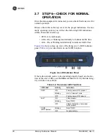
Figure 2-4
shows a close-up view of the transceiver’s LED Indicator
panel.
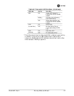
Table 2-2
provides details on each LED function.
Invisible place holder
Figure 2-4. LED Indicator Panel
If the radio network seems to be operating properly based on observa-
tion of the unit’s LEDs, use the
PING
command to verify the link integ-
rity with the Access Point.
Table 2-2. Transceiver LED Functions
LED Label
Activity
Indication
PWR
ON
Primary power (DC) present
Blinking
Unit in “Alarmed” state
OFF
Primary power (DC) absent
LAN*
ON
LAN detected
Blinking
Data TX/RX
OFF
LAN not detected, or excessive
traffic present
COM1
(MGT System)
Blinking
Data TX/RX
OFF
No data activity
Summary of Contents for MDS Mercury Series
Page 2: ......
Page 10: ...2 Mercury Reference Manual 05 4446A01 Rev C ...
Page 28: ...20 Mercury Reference Manual 05 4446A01 Rev C ...
Page 36: ...28 Mercury Reference Manual 05 4446A01 Rev C ...
Page 140: ...132 Mercury Reference Manual 05 4446A01 Rev C ...
Page 142: ...134 Mercury Reference Manual 05 4446A01 Rev C ...
Page 156: ...148 Mercury Reference Manual 05 4446A01 Rev C ...
Page 168: ...160 Mercury Reference Manual 05 4446A01 Rev C ...
Page 184: ...176 Mercury Reference Manual 05 4446A01 Rev C ...
Page 194: ...I 10 Mercury Reference Manual 05 4446A01 Rev C ...

