background image

OB Tables

LOGIQ    500 Advanced Reference Manual
2276614–100  Rev. 0

7–19

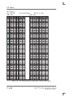
HC : Jeanty

Unit : 

HC (mm)

Jeanty : Radiology

Age (Day)

143 : 513,1982

SD (mm)

HC

Age

SD

HC

Age

SD

<80

n/a

–––

225

169

22

80

93

15

230

173

22

85

95

16

235

176

22

90

98

18

240

180

22

95

100

18

245

184

22

100

102

18

250

188

22

105

104

18

255

192

22

110

107

18

260

196

22

115

109

18

265

200

22

120

111

18

270

204

22

125

114

18

275

208

22

130

116

18

280

213

22

135

119

19

285

217

22

140

121

19

290

221

22

145

124

19

295

225

22

150

126

19

300

230

22

155

129

19

305

235

22

160

131

20

310

240

22

165

134

20

315

245

22

170

136

20

320

250

22

175

139

20

325

255

22

180

141

20

330

260

22

185

144

21

335

265

22

190

146

21

340

270

22

195

149

21

345

275

22

200

151

21

350

281

22

205

154

22

355

286

22

210

157

22

360

292

22

215

161

22

>360

n/a

–––

220

165

22

Table 7–27.  HC : Jeanty

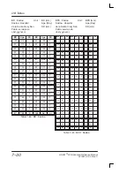
BPD : Kurtz

Unit :

BPD (mm)
Age (Day)
SD (mm)

BPD

Age

SD

BPD

Age

SD

BPD

Age

SD

<21

n/a

–––

47

139

4

74

204

5

21

84

4

48

141

4

75

207

5

22

87

4

49

143

4

76

210

5

23

91

4

50

145

4

77

213

5

24

93

4

51

147

4

78

216

5

25

95

4

52

149

4

79

219

5

26

97

4

53

151

4

80

222

5

27

99

4

54

153

4

81

225

5

28

101

4

55

155

5

82

229

5

29

103

4

56

157

5

83

232

5

30

105

4

57

160

5

84

235

5

31

107

4

58

162

5

85

238

5

32

109

4

59

165

5

86

241

5

33

111

4

60

168

5

87

244

5

34

113

4

61

170

5

88

248

5

35

115

4

62

173

5

89

252

5

36

117

4

63

175

5

90

257

5

37

119

4

64

178

5

91

262

5

38

121

4

65

181

5

92

267

5

39

123

4

66

183

5

93

272

5

40

125

4

67

186

5

94

276

5

41

127

4

68

188

5

95

280

5

42

129

4

69

191

5

96

284

5

43

131

4

70

194

5

97

288

5

44

133

4

71

196

5

98

293

5

45

135

4

72

199

5

>98

n/a

–––

46

137

4

73

201

5

Table 7–28.  BPD : Kurtz

Summary of Contents for Logiq 500

Page 1: ......

Page 2: ...rective 93 42 EEC concerning medical devices This manual is a reference for the LOGIQ 500 PRO Series It applies to all versions of 6 0 software for the LOGIQ 500 GE Medical Systems GE Medical Systems...

Page 3: ...rify that you are using the latest revision of this document Information pertaining to this document is maintained on GPC GE Medical Systems Global Product Configuration If you need to know the latest...

Page 4: ...Revision History LOGIQ 500 Advanced Reference Manual 2276614 100 Rev 0 Revision History B This page left blank intentionally...

Page 5: ...ope Quality Assurance Manager BP 34 F 78533 BUC CEDEX France Tel 33 0 1 30 70 40 40 S Medical Device Good Manufacturing Practice Manual issued by the FDA Food and Drug Administration Department of Hea...

Page 6: ...ed device consult the point of purchase or service representative for further suggestions NOTE The manufacturer is not responsible for any interference caused by using other than recommended interconn...

Page 7: ...res 1 2 Manual Organization 1 4 Manual Content 1 4 Manual Layout 1 5 Operator Controls Sub Menu Displays 2 2 B Mode Top Menu 2 2 CFM Top Menu 2 3 PWD Top Menu 2 4 CWD Top Menu 2 5 M Mode Top Menu 2 6...

Page 8: ...ppler Calculations 4 3 Realtime Doppler Calculations option 4 3 Fetal Trend Management software option 4 8 Overview 4 8 Storing Patient Information 4 8 Growth Trending 4 13 List ID Management 4 14 Dat...

Page 9: ...V Calculation Formulas Bi Plane Ellipsoid Method 4 73 LV Calculation Formulas Gibson Method 4 74 B Mode Analysis Parasternal Long Axis 4 76 B Mode Analysis Parasternal Short Axis PSAX AV 4 77 B Mode A...

Page 10: ...nostic Ultrasound 6 2 Operator Awareness and Actions to Minimize Bioeffect 6 5 Implementing ALARA Methods 6 9 Clinical instructions for fetal use 6 10 Efficacy of Fetal Doppler 6 13 Variance studies f...

Page 11: ...VCR 8 7 Starting the VCR 8 14 Recording Playback Image Search 8 28 Troubleshooting 8 44 DICOM Storage Print Option 9 2 Overview 9 2 DICOM Presets 9 2 Menu Access 9 2 Patient Entry Menu 9 3 Network Con...

Page 12: ...Table of Contents LOGIQ 500 Advanced Reference Manual 2276614 100 Rev 0 Table of Contents 6 This page left blank intentionally...

Page 13: ...Introduction LOGIQ 500 Advanced Reference Manual 2276614 100 Rev 0 1 1 Introduction System Features 1 2 LOGIQ 500 s Features 1 2 Manual Organization 1 4 Manual Content 1 4 Manual Layout 1 5...

Page 14: ...sing scan control spatial resolution temporal resolution and contrast resolution The result is consistent generation of finely detailed anatomical resolution with excellent dynamic contrast tissue ran...

Page 15: ...oday s diverse ultrasound department needs with investment security through reliable upgrades application enhancements and complete product support from GE Improved operator interface and system ergon...

Page 16: ...re listed Modes The 3DvieW and 3D Surface Mode options are detailed Advanced Options Details the options in the different exam categories Realtime Doppler Calculations OB GYN s Fetal Trend Management...

Page 17: ...to highlight the text Graphics Graphics provide a visual guide to the text when possible Push the top or bottom of a rocker switch to get the desired result Turn rotary knobs to the left counterclockw...

Page 18: ...Manual Organization LOGIQ 500 Advanced Reference Manual 2276614 100 Rev 0 1 6 This page left blank intentionally...

Page 19: ...Menu 2 3 PWD Top Menu 2 4 CWD Top Menu 2 5 M Mode Top Menu 2 6 Preset Top Menu 2 6 Set Up Top Menu 2 7 ECG Top Menu 2 7 Image Archive Option Top Menu 2 8 Cine Top Menu 2 8 Auto Sequence Top Menu 2 8 P...

Page 20: ...B 2 2 ATO Create ATO On Off Preset B Set Up ECG Image Softner Imaging Freq Frame Average 3D Mode Color OFF 3 MHz Tag Positn Color Tag Preset B Set Up ECG Focus Positn SGL Preset B Edge Enhance Reject...

Page 21: ...isplay Thrshld Penet Frame Average Set Up ECG 53 0 5 Spatial Filter OFF Color Tag MID Preset CFM Tag Positn W E Cancel Packet Size Set Up ECG Noise Blanker OFF 3D Mode OFF Preset CFM Persist ence MR F...

Page 22: ...ter Slant Scan Set Up ECG 0 20 0 5 ASO Auto Angle Color Tag MID Preset PWD Tag Positn Color Penet Sweep Speed Set Up ECG 40 Preset PWD CFM Shrink CFM PWD Ratio Rejectn HPRF Set Up ECG 1 2 Compo Preset...

Page 23: ...eset CWD Wall Filter Slant Scan Set Up ECG 0 20 0 ASO Auto Angle Color Tag MID Preset CWD Tag Positn Color Sweep Speed Set Up ECG 40 Preset CWD Rejectn Set Up ECG Compo Preset CWD Trace Method Calc Di...

Page 24: ...ECG Figure 2 5 M Mode Sub Menu pages 1 and 2 Preset Top Menu Preset B User Preset 3 Set Up ECG User Preset 2 User Preset 1 User Preset 8 User Preset 7 User Preset 6 User Preset 5 User Preset 4 Preset...

Page 25: ...ustom Display Diag User Define Utility Save Values Figure 2 7 Set Up Sub Menu page 1 of 1 ECG Top Menu Preset B Sync Selectn Set Up ECG Dual Single Aux Wave PCG Wave ECG Wave R Delay Ref Scan 10 Prese...

Page 26: ...re 2 9 Image Archive Sub Menu page 1 of 1 Cine Top Menu Archive Review Loop Auto Seq CINE End Frame Start Frame Side Change Multpl CINE Cine Gauge Loop Speed 1 1 DICOM Archive Auto Seq CINE Capture Fr...

Page 27: ...12 Probe Name Menu Body Pattern Pattern name 2 Pattern name 1 Pattern name 4 Pattern name 3 Pattern name 6 Pattern name 5 Pattern name 8 Pattern name 7 Figure 2 13 Body Pattern Sub Menu Comment Annot...

Page 28: ...Rt Ov H Lt Ov H Rt Ov W Lt Ov W GYN Report Figure 2 15 Typical Measurement Sub Menu Image Recall C B 08 50 C BM 08 53 C BD 08 57 C B B 08 59 B 08 48 BM 08 51 BD 08 54 B 08 58 Figure 2 16 Image Recall...

Page 29: ...RD Report LV CUBED LV BULLET LV SP ELP LV GIBSON PSAX AV PSAX PAP AP 2CH CARD Report PLAX PSAX MV AP 4CH D AV D TV Transf CALCs D MV D PV TRACE AUTO Transf CALCS is only available with Realtime Dopple...

Page 30: ...Sub Menu Displays LOGIQ 500 Advanced Reference Manual 2276614 100 Rev 0 2 12 This page left blank intentionally...

Page 31: ...ion 3 2 Overview 3 2 Functionality in 3D Mode 3 3 Functionality while MIP Image is Displayed 3 3 Mode Changes in 3D Mode 3 3 CFM Map 3 4 Activating 3D Mode 3 4 Creating a MIP Image Rendering 3 7 3D Op...

Page 32: ...for any measurement or computation ability No specific reconstruction resolution or accuracy is provided or claimed for this option Since positional information of the original scan is not available...

Page 33: ...e S Zoom Reference S Dual Image Display S ECG S CWD Probes S User Diagnostics S 3D Surface Functionality while MIP Image is Displayed Additional disabled functions while 3D is displayed are S Cine Cap...

Page 34: ...ivated prior to collecting the desired scan data To activate 3D Mode 2 While in normal B Mode display Sub Menu page 2 Press the Sub Menu Select rocker switch if necessary to display page 2 3 Select 3D...

Page 35: ...4 100 Rev 0 3 5 Activating 3D Mode cont d To avoid confusion with the rendered 3D image ensure that The orientation mark on the probe and the displayed image are properly aligned Orientation Marking O...

Page 36: ...d Image memory will be cleared and the message displayed is Are you sure to erase all the image memory data y n When 3D Mode is activated one half of cine memory is allocated for use by 3D Mode Cine T...

Page 37: ...Remember that Cine memory is limited Activate Cine Gauge by rotating the Cine Scroll knob 3 Display the Cine Sub Menu page 3 by pressing the Sub Menu Select rocker switch Rotate the Cine Scroll knob...

Page 38: ...Images to be used for MIP Image rendering Figure 3 5 Images used for MIP 5 Select Render 3D from the Cine Sub Menu page 3 Depending on the parameters set in Custom Display pages 9 and 18 the system w...

Page 39: ...reshold is used This is available only in B Mode Inverse This technique operates the same as Min The value of the result is inverted No threshold is used This is available only in B Mode Gradient This...

Page 40: ...ue is higher than the set threshold Shade Boundary Threshold The value to be compared to Object Threshold result is lower than the Boundary Threshold Comparison will be made frame by frame after the a...

Page 41: ...urface option is designed for qualitative information only and has no provision for any measurement or computation ability No specific reconstruction resolution or accuracy is provided or claimed for...

Page 42: ...Cine Sub Menu page 4 While in 3D Surface Mode measurements cannot be performed While 3D Surface Mode is active 3D Surface is displayed on the bottom of the screen Auto Seq Archive CINE Opacity AUTO DI...

Page 43: ...ensure that The orientation mark on the probe and the displayed image are properly aligned Orientation Marking Orientation Marking Figure 3 7 Proper Probe Orientation When acquiring the image data pu...

Page 44: ...played than AUTO 1 5 Press SURFACE ROI The ROI box cursor is displayed on the B Mode image and the Cine Loop starts automatically 6 After reviewing the selected CINE images use the Trackball and Scan...

Page 45: ...LAY SURFACE The 3D Surface image disappears S When the Not Enough Memory message is displayed on the bottom of the screen change the size of ROI to small until this message disappears and then press S...

Page 46: ...3D Surface Mode LOGIQ 500 Advanced Reference Manual 2276614 100 Rev 0 3 16 This page left blank intentionally...

Page 47: ...the Number of Fetuses 4 24 Report Page Layout 4 25 OB Graph 4 26 Fetal Trend Management Multigestational Option 4 28 Data Management Center DMC 4 30 Overview 4 30 Operational Setup 4 30 Transferring O...

Page 48: ...l Short Axis PSAX MV 4 78 B Mode Analysis Parasternal Short Axis PSAX PAP 4 79 B Mode Analysis Apical 4 Chamber AP 4CH 4 80 B Mode Analysis Apical 2 Chamber AP 2CH 4 82 M Mode Analysis Left Right Vent...

Page 49: ...y with AMCAL option Soft Menu Changes Page 4 of the PWD soft menu contains 3 selections that affect Realtime Doppler Calculations These are Compo Preset PWD Trace Method Calc Dir Realtim Trace Set Up...

Page 50: ...measurements like FV and TAMEAN is used in the calculations Each measurement menu in all exam categories except GYN and Cardiology with AMCAL option has a selection for PI S D Ratio A B Ratio RI HEAR...

Page 51: ...er for D Realtime Calc 1 5 S RI Calculation to bidirectional flow Off On See the D Realtime Calc preset in Chapter 14 of the Basic User Manual for details on customizing the appearance and content of...

Page 52: ...ltime Calc mode by turning Trace Auto OFF in a measurement menu or selecting Realtime Trace Off in the PWD soft menu Doppler Trace Indicators Each time end diastole is detected in the Realtime Doppler...

Page 53: ...enu page 7 2 Turn on the Realtime Doppler Calculation selection in the Softmenu 3 The selected measurements will be displayed in the upper left portion of the screen 4 Press Freeze 5 Choose Select Loc...

Page 54: ...atient Entry Menu is retained This information is automatically displayed in the Patient Entry Menu on subsequent exams when the patient ID is entered in the Patient Entry Menu If the previous measure...

Page 55: ...acity is reached the message Data is full Delete needless data is displayed However the average MOD can store more than 30 years worth of data using the same assumptions Media Selection Preset Paramet...

Page 56: ...ands are displayed on the OB Graph that relate to the Fetal Trend Management option as shown in Figure 4 3 These commands are LIST ID Displays a list by patient ID number LIST DATA Displays data for a...

Page 57: ...If there are similar files in the data list i e same ID but Name and EDC are different the system displays the Patient List Menu LIST ID The user will have to select the file to which the data will b...

Page 58: ...to save data without a patient name or EDC but the information displayed with the LIST DATA function is limited If all of the data is the same as a file on the data list the message displayed is Over...

Page 59: ...raph display the system automatically searches the storage media and gets the data and displays the OB Trend Graph as shown in Figure 4 4 Figure 4 4 OB Trend Graph The system will search for like data...

Page 60: ...own in Figure 4 5 Figure 4 5 LIST ID Data Display List ID Commands The commands at the bottom of the List ID page allow the user to perform the following functions CTRL N Displays the next page CTRL P...

Page 61: ...xt Page Ctrl P Prvs Page Ctrl A Arrange CLEAR Clear entered characters Arrange 1 ID 2 Name 3 EDC R REV PAGE Ctrl L Data List Ctrl D Delete Ctrl S Search Ctrl M Modify Ctrl K Save Ctrl C Cancel Figure...

Page 62: ...n where y means to proceed with deleting the data n means do nothing The data selected is then deleted from the data base If the user is cleaning up the media especially in the case of the Hard Drive...

Page 63: ...T ID EDD MM DD YY NUMBER Operator Message Area DATA LIST MENU 1 2 3 4 5 6 7 8 No GA MEAS1 MEAS2 MEAS3 MEAS4 MEAS5 MEAS6 MEAS7 MEAS8 UNIT1 UNIT2 UNIT3 UNIT4 UNIT5 UNIT6 UNIT7 UNIT8 AUTH1 AUTH2 AUTH3 AU...

Page 64: ...e selected patient information is displayed and the cursor moves to the PT NAME window Use the Trackball to highlight the desired window and change the necessary information with the alphanumeric keys...

Page 65: ...ile Press Ctrl S simultaneously The cursor moves to the PT Name window as shown in Figure 4 9 Figure 4 9 Search Data Entry Use the Trackball to highlight the desired window and type the necessary info...

Page 66: ...2 3 4 5 6 7 8 No GA MEAS1 MEAS2 MEAS3 MEAS4 MEAS5 MEAS6 MEAS7 MEAS8 UNIT1 UNIT2 UNIT3 UNIT4 UNIT5 UNIT6 UNIT7 UNIT8 AUTH1 AUTH2 AUTH3 AUTH4 AUTH5 AUTH6 AUTH7 AUTH8 123 W D 123 W D 123 W D 123 W D 123...

Page 67: ...B allow the user to move to the right and left respectively to display additional measurements calculations Control G Control G enables the OB Graph function for the number of files selected Press Ctr...

Page 68: ...FETUS NUMBER The factory default number is one Entering Fetus Number It is generally during the first exam that the user recognizes a multiple gestation If during the first exam more than one fetus is...

Page 69: ...to describe placenta location of the fetus This is displayed as POS PLAC Measurements Calculations During measurements calculations all measurements are performed on fetus A first The user then switc...

Page 70: ...fetus n returns to the previous number If a fetus number increase is not available the message Data range over Input proper data is displayed Number Decrease If the fetus number has been decreased on...

Page 71: ...lculations found on page one However all fetuses maximum of 4 are dipslayed on this page Since page one is different by region page three is also different by region selected i e USA European Tokyo Un...

Page 72: ...to display graphs for individual fetuses as well as a graph to plot all fetuses simultaneously For individual fetus reports the fetus is designated by fetus ID and total number of fetuses i e Fetus A...

Page 73: ...ont d If all fetuses are displayed simultaneously different symbols are used to mark each fetus The symbols are Fetus Present A B C D Figure 4 12 OB Graph Multigestational Option Osaka University Vers...

Page 74: ...estational Fetal Trend Graph Figure 4 13 Fetal Trend Graph Multigestational Option Hadlock USA Version Save Function The SAVE command on the trend graph display or Ctrl K in the Data List display will...

Page 75: ...anual 2276614 100 Rev 0 4 29 Data List Menu The Data List Menu of fetal trend information is slightly different with the Multigestational Option Each fetus has it s own display page as shown in Figure...

Page 76: ...the patient entry menu NOTE Data Management Center transfer function will not work if the fetus number is greater than one with the Multigestation Option An error message appears Multigestation data t...

Page 77: ...nput all necessary information into the Patient Entry Menu Scan the patient Measure and calculate all the desired parameters Press Record 1 or Record 2 depending on the key assignment Communication wi...

Page 78: ...m the PC Check Computer Checksum Error occurred LOGIQ 500 senses an abnormal acknowledge ment from the PC after all data has been sent Check Computer No response LOGIQ 500 senses no acknowledgement fr...

Page 79: ...es of the same measurement Only the average of selected measurements will be transferred S The system keyboard is locked out during the transfer of data S Only the Record 1 or Record 2 keys can start...

Page 80: ...abling Assign Computer to the proper LOGIQ 500 serial port in the Setup System Parameter Menu page 5 Display the New Patient Entry Menu on the LOGIQ 500 Send Data On the PC read the hospital ID card w...

Page 81: ...fer to Table 4 1 on 4 32 for error messages in patient data transfer If the New Patient Entry Menu is not displayed when the PC tries to send data the error message Can t receive data Return to New Pa...

Page 82: ...ations A page of measurements is also added to the cardiac calculation menu This page varies with scan mode Additional scan mode measurement categories are B Mode Parasternal Long Axis PLAX Parasterna...

Page 83: ...m the first menu layer The system then prompts the user to perform a series of measurements in sequence This measurement sequence can be modified by the user if the factory sequence is not satisfactor...

Page 84: ...ete the calculation or calculation sequence 2 Measurements and resultant calculations will be displayed in the designation area Only those measurements displayed are available for re measurement 3 Pre...

Page 85: ...can be remeasured separately If a measurement is selected from the soft menu during the re measure process the re measurement process is cancelled and the old value is restored After a re measurement...

Page 86: ...m Prior Edge 0 2000msec Automatic If Auto is selected the determination is made by comparing the displayed B Mode or M D Mode image frames with the R point on the ECG wave Therefore s for systole and...

Page 87: ...ion Auto Trace Measurements Doppler measurement menus D AV D MV D PV and D TV each have a selection called Auto Trace When the user selects Auto Trace the start point and end point of a measurement is...

Page 88: ...e next start point LVPWd IVSd RV IVS LV LVPW RVDd LVIDd Figure 4 16 Continuous M Mode Measurements This type of M Mode measurements is supported by M LV RV Teichholz Cubed and Gibson menu selections A...

Page 89: ...Set Up Preset Program menu pages 5 and 6 If the measurement is set to OFF in the Preset Program menus it will not appear in the continuous sequence Additional Set points will have to be made if measur...

Page 90: ...Advanced Cardiac Calculations LOGIQ 500 Advanced Reference Manual 2276614 100 Rev 0 4 44 AMCAL Sub Menus First Layer Figure 4 17 First Layer Sub Menus...

Page 91: ...ulations LOGIQ 500 Advanced Reference Manual 2276614 100 Rev 0 4 45 AMCAL Sub Menus Second Layer Automatic Determination of Systole Diastole Figure 4 18 Cubed Teichholz and Gibson Sub Menus Figure 4 1...

Page 92: ...Calculations LOGIQ 500 Advanced Reference Manual 2276614 100 Rev 0 4 46 AMCAL Sub Menus Second Layer Automatic Determination of Systole Diastole cont d Figure 4 20 LV SP DISC Sub Menus Figure 4 21 LV...

Page 93: ...LOGIQ 500 Advanced Reference Manual 2276614 100 Rev 0 4 47 AMCAL Sub Menus Second Layer Automatic Determination of Systole Diastole cont d Figure 4 22 Modified Simpson s Rule Sub Menus Figure 4 23 Sin...

Page 94: ...alculations LOGIQ 500 Advanced Reference Manual 2276614 100 Rev 0 4 48 AMCAL Sub Menus Second Layer Automatic Determination of Systole Diastole cont d Figure 4 24 Biplane Ellipsoid Sub Menus Figure 4...

Page 95: ...LOGIQ 500 Advanced Reference Manual 2276614 100 Rev 0 4 49 AMCAL Sub Menus Second Layer Automatic Determination of Systole Diastole cont d Figure 4 26 PSAX AV Sub Menus Figure 4 27 PSAX MV Sub Menus F...

Page 96: ...iac Calculations LOGIQ 500 Advanced Reference Manual 2276614 100 Rev 0 4 50 AMCAL Sub Menus Second Layer Automatic Determination of Systole Diastole cont d Figure 4 29 AP 4CH Sub Menus Figure 4 30 AP...

Page 97: ...ons LOGIQ 500 Advanced Reference Manual 2276614 100 Rev 0 4 51 AMCAL Sub Menus Second Layer Automatic Determination of Systole Diastole cont d Figure 4 31 M LV RV Sub Menus Figure 4 32 M MV Sub Menus...

Page 98: ...ions LOGIQ 500 Advanced Reference Manual 2276614 100 Rev 0 4 52 AMCAL Sub Menus Second Layer Automatic Determination of Systole Diastole cont d Figure 4 34 M PV Sub Menus Figure 4 35 M TV Sub Menus Fi...

Page 99: ...rdiac Calculations LOGIQ 500 Advanced Reference Manual 2276614 100 Rev 0 4 53 AMCAL Sub Menus Second Layer Automatic Determination of Systole Diastole cont d Figure 4 37 D AV Sub Menus Figure 4 38 D T...

Page 100: ...Advanced Cardiac Calculations LOGIQ 500 Advanced Reference Manual 2276614 100 Rev 0 4 54 AMCAL Sub Menus Second Layer Automatic Determination of Systole Diastole cont d Figure 4 39 D PV Sub Menus...

Page 101: ...alculations LOGIQ 500 Advanced Reference Manual 2276614 100 Rev 0 4 55 AMCAL Sub Menus Second Layer Manual Determination of Systole Diastole Figure 4 40 Cubed Teichholz and Gibson Sub Menus Figure 4 4...

Page 102: ...Calculations LOGIQ 500 Advanced Reference Manual 2276614 100 Rev 0 4 56 AMCAL Sub Menus Second Layer Manual Determination of Systole Diastole cont d Figure 4 42 LV SP DISC Sub Menus Figure 4 43 LV BP...

Page 103: ...s LOGIQ 500 Advanced Reference Manual 2276614 100 Rev 0 4 57 AMCAL Sub Menus Second Layer Manual Determination of Systole Diastole cont d Figure 4 44 Modified Simpson s Rule Sub Menus Figure 4 45 Sing...

Page 104: ...ns LOGIQ 500 Advanced Reference Manual 2276614 100 Rev 0 4 58 AMCAL Sub Menus Second Layer Manual Determination of Systole Diastole cont d Figure 4 46 Biplane Ellipsoid Sub Menus Figure 4 47 PLAX Sub...

Page 105: ...anual 2276614 100 Rev 0 4 59 AMCAL Sub Menus Second Layer Manual Determination of Systole Diastole cont d Figure 4 48 PSAX AV Sub Menus Manual Determination Figure 4 49 PSAX MV Sub Menus Manual Determ...

Page 106: ...IQ 500 Advanced Reference Manual 2276614 100 Rev 0 4 60 AMCAL Sub Menus Second Layer Manual Determination of Systole Diastole cont d Figure 4 51 AP 4CH Sub Menus Manual Determination Figure 4 52 AP 2C...

Page 107: ...Cardiac Calculations LOGIQ 500 Advanced Reference Manual 2276614 100 Rev 0 4 61 AMCAL Sub Menus Second Layer Manual Determination of Systole Diastole cont d Figure 4 53 M LV RV Sub Menus Manual Deter...

Page 108: ...Measurements Calculations and Cardiology of this manual set The system will prompt the user for any measurements necessary to complete a selected sequence Customizing Measurement Sequences The sequen...

Page 109: ...to the main or Sub Menu area Press Set The pop up menu is displayed While the pop up menu is displayed use the up down Trackball motion or the Up Down arrow keys to select the desired menu item Use t...

Page 110: ...left Use the Trackball to move the highlight cursor to the first measurement to be made in the customized sequence Press Set The number one is placed to the left of that item Use the Trackball to mov...

Page 111: ...leting or saving the order the following message is displayed Quit Press ESC to cancel SET to confirm Set exits from this screen Esc causes nothing to happen If a new sequence programming was complete...

Page 112: ...B Mode M Mode Figure 4 55 Cubed Method Measurements Refer to Chapter 10 Cardiology of the Basic User Manual for the following Cubed Method Formulas LVIDd LVIDs IVSd IVSs LVPWd LVPWs HR ET EdV EsV FS...

Page 113: ...od Formulas LVIDd LVIDs IVSd IVSs LVPWd LVPWs HR ET EdV EsV FS SV EF and CO Calc Mnemonic Calc Name Input Measurements Formula SI Stroke Volume Index body surface area and SV SI ml m 2 SV BSA CI Cardi...

Page 114: ...nic Calc Name Input Measurements Formula SI Stroke Volume Index body surface area and SV SI ml m 2 SV BSA CI Cardiac Index body surface area and CO CI ml min m 2 CO BSA Table 4 4 Bullet Method Calcula...

Page 115: ...circle EdV 1 20 LVLd 20 a2 di i 1 EsV End Systole Volume one distance and two areas by ellipse trace or circle EsV 2 20 LVLs 20 a2 si i 1 SV Stroke Volume two distances and two areas by ellipse trace...

Page 116: ...LVA4d Left Ventricular Area Apical 4 Chamber Diastole one area by trace only is divided into 20 elliptical disk segments LVA4d a1 cm 2 LVA4s Left Ventricular Area Apical 4 Chamber Systole one area by...

Page 117: ...EsV EF Ejection Fraction two distances and two areas by ellipse trace or circle EF SV EdVx100 CO Cardiac Output two distances and two areas by ellipse trace or circle and one 2 beat time interval CO...

Page 118: ...y surface area and SV SI ml m 2 SV BSA CI Cardiac Index body surface area and CO CI ml min m 2 CO BSA Table 4 7 Modified Simpson s Rule Method Calculation Formulas LV Calculation Formulas Single Plane...

Page 119: ...asurements Refer to Chapter 10 Cardiology of the Basic User Manual for the following Bi Plane Ellipsoid Method Formulas LVMLd LVMLs LVAMd LVAMs LVAd LVAs HR EdV EsV SV EF and CO Calc Mnemonic Calc Nam...

Page 120: ...ter Systole one distance LVIDs d1 cm or mm IVSd Interventricular Septal Thickness Diastole one distance IVSd d1 cm or mm IVSs Interventricular Septal Thickness Systole one distance IVSs d1 cm or mm LV...

Page 121: ...ning two distances FS 1 LVIDs LVIDd x100 SV Stroke Volume two distances SV ml EdV EsV EF Ejection Fraction two distances EF SV EdVx100 CO Cardiac Output two distances and one 2 beat time interval CO 1...

Page 122: ...Left Ventricular Interior Dimension at Diastole one distance LVIDd d1 cm or mm AOs Aortic Root Dimension at Systole one distance AOs d1 cm or mm LVIDs Left Ventricular Interior Di mension at Systole o...

Page 123: ...cm or mm AOs Aortic Root Dimension at Systole one distance AOs d1 cm or mm PADs Pulmonary Artery Diame ter at Systole one distance PADs d1 cm or mm LADML Left Atrium Medial Lateral Diameter at Systole...

Page 124: ...Formula LVAMd Left Ventricular Area Mitral Valve Diastole one area by ellipse trace or circle LVAMd a1 cm 2 LVAMs Left Ventricular Area Mitral Valve Systole one area by ellipse trace or circle LVAMs...

Page 125: ...Mnemonic Calc Name Input Measurements Formula LVAPd Left Ventricular Area Papillary Muscles at Diastole one area by ellipse trace or circle LVAPd a1 cm 2 LVAPs Left Ventricular Area Papillary Muscles...

Page 126: ...ellipse trace or circle LVAd a1 cm 2 LVLd Left Ventricular Length Dimension Diastole one distance LVLd d1 cm or mm LVMLd Left Ventricular Medial Lateral Dimension Diastole one distance LVMLd d1 cm or...

Page 127: ...s Right Ventricular Length Dimension at Systole one distance RVLs d1 cm or mm RVMLs Right Ventricular Medial Lateral Dimension Systole one distance RVMLs d1 cm or mm TAML Tricuspid Annulus Medial Late...

Page 128: ...cm 2 LVLd Left Ventricular Length Dimension Diastole one distance LVLd d1 cm or mm LVMLd Left Ventricular Medial Lateral Dimension Diastole one distance LVMLd d1 cm or mm LVAs Left Ventricle Area Sys...

Page 129: ...e distance IVSs d1 cm or mm LVPWs Left Ventricular Posterior Wall Thickness at Systole one distance LVPWs d1 cm or mm LVIDs Left Ventricular Interior Dimension at Systole one distance LVIDs d1 cm or m...

Page 130: ...D_CE Mitral Valve C E Separation one distance D_CE d1 cm or mm T_AC Mitral Valve A C Interval one time interval T_AC t1 msec or sec P R P R Interval one time interval P R t1 msec or sec HR Heart Rate...

Page 131: ...ium Dimension Systole one distance C D LADs d1 cm or mm RVOTs Right Ventricular Outflow Tract Diameter at Systole one distance G H RVOTs d1 cm or mm LVPEP Left Ventricle Pre Ejection Period one time i...

Page 132: ...PEP Right Ventricle Pre Ejection Period one time interval RVPEP t1 msec or sec RVET Right Ventricle Ejection Time one time interval RVET t1 msec or sec aWAVE Pulmonic Valve a Wave Amplitude one distan...

Page 133: ...C E Amplitude one distance TV_CE d1 cm or mm TV_AC Tricuspid Valve A C Interval one time interval TV_AC t1 msec or sec P R P R Interval one time interval P R t1 msec or sec HR Heart Rate beats minute...

Page 134: ...rea by ellipse trace or circle MVOA a1 cm 2 PFVMV Peak Flow Velocity at the Mitral Valve one velocity PFV MV v1 cm s or m s PFVLA Peak Flow Velocity at Left Atrium one velocity PFV LA v1 cm s or m s E...

Page 135: ...ow Velocity flow velocities one area by ellipse trace or circle MeanFV cm s or m s FVI t FVI SV Stroke Volume flow velocities and one area by ellipse trace or circle SV ml FVI x MVOA SI Stroke Volume...

Page 136: ...tic Valve flow velocities FVI AV mm or cm Vdt FVI LV Flow Velocity Intergal at Left Ventricular Outflow Tract flow velocities FVI LV mm or cm Vdt PFVAV Peak Flow Velocity at Aortic Valve one velocity...

Page 137: ...one velocity one time interval PkFVI mm or cm 1 14 x PFV AV x ET 20 03 MeanFV Mean Flow Velocity flow velocities one time interval MeanFV cm s or m s FVI t FVI QP QS QP QS Ratio two CO QP QS CO PV CO...

Page 138: ...tricle Outflow Tract one FVI FVI RV Vdt PFVPA Peak Flow Velocity at Pul monic Aorta one velocity PFVPA v1 cm s or m s PFVRV Peak Flow Velocity at Right Ventricle Outflow Tract one velocity PFVRV v1 cm...

Page 139: ...eanFV mm or cm FVI t FVI QP QS QP QS Ratio two CO QP QS CO PV CO AV CO Cardiac Output flow velocities one area by ellipse trace or circle and one time interval CO ml SVxHR 1000 CI Cardiac Index body s...

Page 140: ...ies FVI mm or cm Vdt PFVTV Peak Flow Velocity at Tri cuspid Valve one velocity PFVTV v1 cm s or m s PFVRA Peak Flow Velocity at Right Atrial one velocity PFVRA v1 cm s or m s ET Ejection Time one time...

Page 141: ...locity one time in terval MeanFV cm s or m s FVI t FVI MaxPG Maximum Pressure Gradient two velocities MaxPG mmHg 4 x PFV TV 2 MeanPG Mean Pressure Gradient flow velocities MeanPG mmHg n 4 x V 2 n i 1...

Page 142: ...Q 500 Advanced Cardiac Calculation option The first format is the standard display that shows a separate page for each of the first layer menu choices i e Cubed Method Bullet Method PSAX AV D MV etc A...

Page 143: ...port pages could be generated The List type of reporting can be customized to the user s needs eliminating unnecessary printing requirements A List type report page is shown in Figure 4 82 SEX HEIGHT...

Page 144: ...o quickly display reports To display a pop up menu use the Trackball to move the highlight cursor to the main or Sub Menu area Press Set The pop up menu is displayed While the pop up menu is displayed...

Page 145: ...List type report displays only those measurements or calculations actually performed The section order of the list is the same that was programmed by the S RP command The item order is the same as the...

Page 146: ...t Report Display Order Commands at the bottom of this Select Report Display allow the user to ORDER Erases all previous print order numbers and starts the order selection process RESET Resets the prin...

Page 147: ...lection Press Set The order number is placed to the left of the measurement group name The highlighted cursor stays in it s position until it is moved by the Trackball to the next selection Continue t...

Page 148: ...to happen If the Order process was not completed the following message is displayed Complete the present set up first EXIT If the exit command is selected before choosing completing or saving a new s...

Page 149: ...ges The Stenosis measurement can be performed by either a distance or area measurement in Advanced Vascular The Stenosis Calculation preset found on Set Up Preset Program page 4 erases all previous St...

Page 150: ...DICAd Rt DICAs Rt MICAd Rt MICAs Carotid Report Rt PICAd Rt ECAd Rt ECAs Page Six HEART RATE Page Two Rt PICAs Rt DCCAd Rt MCCAd Rt MCCAs Rt PCCAd Page Three Rt DCCAs Rt PCCAs Venous Report Carotid Re...

Page 151: ...Side RIGHT Rt Rt MICA Rt PICA Rt ECA Manual Calc Rt DCCA Select Location Rt PI Rt RI Rt A B Ratio Rt S D Ratio Transf CALCs TRACE AUTO Page Four HEART RATE Carotid Report Rt Sten Venous Report Select...

Page 152: ...ed Vascular Calculation Sub Menu with Realtime Doppler ON NOTE The Advanced Vascular Sub Menu changes when the Realtime Doppler option is installed and turned ON Shaded areas denote the differences Wi...

Page 153: ...1 Page one is a summary of the left and right carotid measurements plus Doppler measurements and Stenosis at three different sites Figure 4 87 Carotid Report Page 1 Provisions are made to annotate th...

Page 154: ...will be placed in brackets i e A R B or T B M The user can freely edit the stenosis location names A1 and Doppler site names B1 A maximum of five characters can be used for each site name Advanced Vas...

Page 155: ...on the left and right sides Figure 4 89 shows an example of the layout for page three Figure 4 89 Carotid Report Page 3 On pages two and three the user can choose to display the maximum average or lat...

Page 156: ...hows the layout of the Venous Comments page Figure 4 90 Venous Comment Report Page Abbreviations Abbreviations found on the Venous Comments page designate the following CFV Common Femoral Vein SFV Sup...

Page 157: ...on or release of proximal limb compression Ph Phasicity Indicates the waxing and waning of the velocity signal with respiration Rf Reflux Indicates reverse or backward venous flow was observed Cn Cont...

Page 158: ...d flow peak velocity RT PICAs v1 cm s or m s Rt ECAd Right External Carotid Artery Velocity diastole one Doppler blood flow peak velocity RT ECAd v1 cm s or m s Rt ECAs Right External Carotid Artery V...

Page 159: ...peak velocity RT SUBC v1 cm s or m s Rt PI Right Pulsatility Index two Doppler blood flow peak velocities and TAMAX Rt PI Vmax Vdiastole TAMAX NOTE Rt RI Right Resistivity Index two Doppler blood flow...

Page 160: ...ogy Calculation software option Urology Summary Report Urology Report Page The Urology Report Page is is provided to improve productivity and facilitate consistency in Urology procedures It is availab...

Page 161: ...or that specific volume measurement may be added to the right of the volume measurement The third area is for Lesion Sites A description can be input maximum 20 characters each for each lesion site To...

Page 162: ...A to be calculated two ways The two selections are PSAD Prostatic Specific Antigen PSA Density defined as PSAD PSA Volume PPSA Predicted Prostate Specific Antigen defined as PPSA Volume PPSA Coefficie...

Page 163: ...olume measurement named STVOL is available with the Urology Calculation Option A stepper volume calculation STVOL is now available with the LOGIQ 500 when using the ERB7 probe with the stepping device...

Page 164: ...end toward the probe handle 5 Place a rubberband twist lock over the sheath at the end of the probe shaft Ensure the rubberband twist lock is tight around the sheath Rub your finger over the tip of t...

Page 165: ...red at each slice is then used to compute the total volume of the organ according to the following model For N slices there are N 1 volumes between the slices plus a small volume at each end It is ass...

Page 166: ...ional slice Used with the LOGIQ 500 Stepper Volume Calculation a complete three dimensional volume calculation can be made of an organ The needle placement guide template matches the LOGIQ 500 electro...

Page 167: ...ence Manual 2276614 100 Rev 0 5 1 User Maintenance Quality Assurance 5 2 Introduction 5 2 Typical Tests to Perform 5 3 Baselines 5 6 Periodic Checks 5 6 Results 5 7 System Setup 5 8 Test Procedures 5...

Page 168: ...est interests of every ultrasound user to routinely monitor equipment performance The frequency of Quality Assurance evaluations should be based on user s specific needs and clinical practice Periodic...

Page 169: ...rd of system performance trends Frequency of tests Quality assurance tests are used to determine whether a scanner is providing the same level of performance from day to day The frequency of testing v...

Page 170: ...ly positioned to provide information for a variety of tests Doppler phantoms are currently expensive and complicated to deal with on the user level If a problem with any Doppler parameters or measurem...

Page 171: ...4 6 8 10 12 14 16 RMI 403GS 1 2 4 6 5 3 7 8 1 3 5 6 4 2 7 RMI 405GSX 1 Penetration 2 Axial Distance Measurement 3 Functional Resolution 4 Lateral Resolution 5 Lateral Distance Measurement 6 Axial Reso...

Page 172: ...on the monitor should be recorded for the permanent record Periodic Checks Periodic checks are performed on a regular basis as previously recommended For the data to be valid periodic checks should m...

Page 173: ...Assurance Evaluation results should be compared to previously recorded results Performance trends can then be detected Unacceptable performance or diminishing trends should be identified for maintenan...

Page 174: ...mal viewing of a good gray scale image 2 Check all recording devices for proper duplication of image monitor Ensure that what is seen is what is recorded Check the B W or Color page printer VCR MIC or...

Page 175: ...ed To measure axial distance 1 Scan a test phantom with precisely spaced vertical pin targets Adjust all scan controls as necessary for the best image of the pin targets to typical depths for the prob...

Page 176: ...re lateral distance 1 Scan a test phantom with precisely spaced horizontal pin targets Adjust all scan controls as necessary for the best image of the pin targets from side to side 2 Press Freeze to s...

Page 177: ...rasound image To measure Axial resolution 1 Scan a test phantom with precisely spaced vertical pin targets 2 Adjust all scan controls as necessary for the best image of the pin targets to typical dept...

Page 178: ...to improper interpretation of the ultrasound image To measure lateral resolution 1 Scan a test phantom with precisely spaced horizontal pin targets 2 Adjust all scan controls as necessary for the bes...

Page 179: ...w echoes begin to fade as depth is increased The maximum depth of penetration is the point at which homogeneous material in the phantom begins to lose brightness To measure penetration 1 Set the front...

Page 180: ...re the system is capable of resolving at a given depth To measure functional resolution 1 Set the front panel TGC slide pots to their center detent position 2 Gain and acoustic output can be adjusted...

Page 181: ...om with echogenic targets of different sizes and depths should be used To measure contrast resolution 1 Set the front panel TGC slide pots to their center detent position Set dynamic range to 54 db 2...

Page 182: ...the hard copy and video display are equal 2 Scan the phantom and it s echogenic contrast targets 3 Make a hard copy photograph of the display and compare it to the image on the video monitor for contr...

Page 183: ...assurance Acoustic Output Gain Depth Probe Dynamic Range Set up new patient to be the name of the test Annotate the following Any control where its value is NOT displayed Significant phantom informat...

Page 184: ...zontal Measurement Accuracy Axial Resolution Lateral Resolution Penetration Functional Resolution Contrast Resolution Gray Scale Photography Performed By Date System Serial Number Probe Type Probe Mod...

Page 185: ...hods 6 9 Clinical instructions for fetal use 6 10 Efficacy of Fetal Doppler 6 13 Variance studies for fetal Doppler measurements 6 16 Training and User Assistance 6 17 FDA Acoustic Output Tables 6 18...

Page 186: ...effects aka bioeffects of either a mechanical or thermal nature Although the generation of bioeffect is intentional with therapeutic ultrasound it is generally undesired in diagnostic applications and...

Page 187: ...tes of heat production and heat transfer The susceptibility of some tissues to injury from heat such as developing fetal tissue further complicate the concern for long term effects The time average de...

Page 188: ...racteristics of tissue such as the presence and size of microscopic gas bubbles and the sensitivity of the tissue to the effects of cavitation will influence the potential for and magnitude of cavitat...

Page 189: ...ates as it passes through the tissue causing the deeper tissue to encounter much lower levels Some tissues like bone readily convert ultrasound energy to heat while others like blood and amniotic flui...

Page 190: ...cing bioeffect The indices are based on mathematical models and each is normalized so that the potential for bioeffect becomes more significant as the indices reach a value 1 0 or larger A mechanical...

Page 191: ...ention When conditions indicate a potential for harmful bioeffect the operator should take action promptly to reduce the risk by changing equipment settings or altering procedural techniques Output di...

Page 192: ...ricted by the type of examination or clinical objectives Therefore some examinations may require relatively high output levels to achieve success The decision to raise acoustic output to potentially h...

Page 193: ...as a cautious approach for dealing with uncertain hazards but has since become the principle method for reducing the risk of injury from hazards that do not have safe minimum threshold While no minim...

Page 194: ...ing in discernible clicks or sounds similar to valve movement on cardiac auscultation When the image is obtained adjust the controls in order to optimize the image by reducing the power output to the...

Page 195: ...ermit examination of an area where the artery can be seen at a more advantageous angle Indices of pulsatility if calculated should be determined for each of several heartbeats and averaged Uterine art...

Page 196: ...ly with duplex ultrasound systems The fetal heart should be carefully examined in all standard planes to determine whether or not the anatomy is normal These planes should include four chamber view lo...

Page 197: ...elated with adverse outcome10 11 and may warrant immediate intervention Conversely a normal waveform in the umbilical artery has been rarely associated with stillbirth in a high risk pregnancy Cardiac...

Page 198: ...with the evolution of any new diagnostic technique the indications for use may change when new experimental data become available Suggested Guidelines Following are suggested guidelines prepared by Ha...

Page 199: ...This process is repeated at least twice more and the results from the three studies are averaged Although the S D ratio is in theory an angle independent measurement there may be differences in the ra...

Page 200: ...ter operator variances The recommended protocol for such a clinical trial is 1 Select at least 20 high risk patients 2 For each patient select at least one Doppler waveform from the same fetal artery...

Page 201: ...dicated by their titles the following references are intended to provide additional detailed information concerning bioeffects 1 Standard for Real Time Display of Thermal and Mechanical Acoustic Outpu...

Page 202: ...chievable with the LOGIQ 500 for all probes and operational modes It is intended that this information be useful in making ALARA decisions and selecting the most appropriate probe for the application...

Page 203: ...Value 1 1 8 2 1 pr 3 MPa eter Wo mW 147 8 147 8 arame min of W 3 z1 ITA 3 z1 mW tic Pa z1 cm cousti zbp cm soc Ac zsp cm Asso deq zsp cm fc MHz 2 6 2 6 Dim of Aaprt X cm 2 3 2 3 Y cm 1 0 1 0 PD sec at...

Page 204: ...2 0 pr 3 MPa eter Wo mW 98 5 37 5 136 0 arame min of W 3 z1 ITA 3 z1 mW tic Pa z1 cm cousti zbp cm oc Ac zsp cm 3 8 Asso deq zsp cm 0 3 fc MHz 2 6 2 6 2 6 Dim of Aaprt X cm 2 3 2 3 2 3 Y cm 1 0 1 0 1...

Page 205: ...m cousti zbp cm 2 3 soc Ac zsp cm 3 7 3 7 Asso deq zsp cm 1 0 fc MHz 2 7 3 3 3 3 3 3 3 3 Dim of Aaprt X cm 1 7 1 7 1 7 1 7 Y cm 1 0 1 0 1 0 1 0 PD sec 0 6 ation PRF Hz 651 0 ormat pr PIImax MPa 4 0 er...

Page 206: ...min of W 3 z1 ITA 3 z1 mW amete z1 cm c Para zbp cm oustic zsp cm 3 7 3 7 c Aco deq zsp cm 1 0 Assoc fc MHz 2 7 3 3 3 3 2 7 A Dim of Aaprt X cm 1 7 1 7 2 3 Y cm 1 0 1 0 1 0 on PD sec 0 6 rmatio PRF H...

Page 207: ...1 Aaprt 1 scan Global Maximum Index Value 1 1 1 pr 3 MPa eter Wo mW arame min of W 3 z1 ITA 3 z1 mW tic Pa z1 cm cousti zbp cm oc Ac zsp cm Asso deq zsp cm fc MHz Dim of Aaprt X cm Y cm PD sec ation P...

Page 208: ...aprt 1 scan Global Maximum Index Value 1 1 1 1 1 pr 3 MPa Wo mW er min of W 3 z1 ITA 3 z1 mW amete z1 cm c Para zbp cm oustic zsp cm oc Aco deq zsp cm Assoc fc MHz A Dim of Aaprt X cm Y cm PD sec n PR...

Page 209: ...z1 ITA 3 z1 mW ramet z1 cm c Par zbp cm coustic zsp cm 3 9 3 7 oc Aco deq zsp cm 0 6 Asso fc MHz 3 2 2 5 2 5 Dim of Aaprt X cm 1 5 1 5 Y cm 1 0 1 0 PD sec 0 8 ation PRF Hz 651 0 forma pr PIImax MPa 3...

Page 210: ...er min of W 3 z1 ITA 3 z1 mW amete z1 cm c Para zbp cm oustic zsp cm 3 9 3 7 c Aco deq zsp cm 0 6 Assoc fc MHz 3 2 2 5 3 3 A Dim of Aaprt X cm 1 5 1 5 Y cm 1 0 1 0 n PD sec 0 8 mation PRF Hz 651 0 nf...

Page 211: ...l Maximum Index Value 1 2 1 1 pr 3 MPa 3 2 eter Wo mW arame min of W 3 z1 ITA 3 z1 mW stic Pa z1 cm Acous zbp cm soc A zsp cm 1 3 Ass deq zsp cm fc MHz 6 7 Dim of Aaprt X cm Y cm on PD sec 0 2 mation...

Page 212: ...imum Index Value 1 2 1 1 1 1 pr 3 MPa 3 2 Wo mW er min of W 3 z1 ITA 3 z1 mW amete z1 cm c Para zbp cm oustic zsp cm 1 3 oc Aco deq zsp cm Assoc fc MHz 1 3 A Dim of Aaprt X cm Y cm PD sec 0 2 n PRF Hz...

Page 213: ...min of W 3 z1 ITA 3 z1 mW ramet z1 cm c Par zbp cm coustic zsp cm 1 1 1 1 oc Aco deq zsp cm 0 2 Asso fc MHz 6 7 6 7 Dim of Aaprt X cm 0 6 Y cm 0 7 PD sec 0 4 ation PRF Hz 1300 0 forma pr PIImax MPa 5...

Page 214: ...1 1 1 pr 3 MPa 4 2 Wo mW er min of W 3 z1 ITA 3 z1 mW amete z1 cm c Para zbp cm oustic zsp cm 1 1 c Aco deq zsp cm Assoc fc MHz 6 7 A Dim of Aaprt X cm Y cm n PD sec 0 4 mation PRF Hz 1300 0 nform pr...

Page 215: ...lue 1 2 1 1 2 pr 3 MPa 2 7 eter Wo mW 28 6 arame min of W 3 z1 ITA 3 z1 mW tic Pa z1 cm cousti zbp cm soc Ac zsp cm 2 1 Asso deq zsp cm fc MHz 5 2 5 2 Dim of Aaprt X cm 0 6 Y cm 0 5 PD sec 0 1 ation P...

Page 216: ...1 2 1 1 1 1 0 pr 3 MPa 2 7 Wo mW 23 7 er min of W 3 z1 ITA 3 z1 mW amete z1 cm c Para zbp cm oustic zsp cm 2 1 oc Aco deq zsp cm Assoc fc MHz 2 1 5 2 A Dim of Aaprt X cm 0 6 Y cm 0 5 PD sec 0 1 n PRF...

Page 217: ...ustic zsp cm 2 1 2 3 oc Aco deq zsp cm 0 5 Asso fc MHz 5 2 5 0 5 0 5 0 5 0 Dim of Aaprt X cm 0 8 0 8 0 8 0 8 Y cm 0 5 0 5 0 5 0 5 PD sec 0 1 ation PRF Hz 9372 6 forma pr PIImax MPa 3 4 er Inf deq PIIm...

Page 218: ...1 ITA 3 z1 mW amete z1 cm c Para zbp cm oustic zsp cm 2 1 2 3 c Aco deq zsp cm 0 5 Assoc fc MHz 5 2 5 0 5 0 5 0 A Dim of Aaprt X cm 0 8 0 8 0 8 Y cm 0 5 0 5 0 5 n PD sec 0 1 mation PRF Hz 9372 6 nform...

Page 219: ...Maximum Index Value 1 0 1 1 pr 3 MPa 3 0 eter Wo mW arame min of W 3 z1 ITA 3 z1 mW tic Pa z1 cm cousti zbp cm soc Ac zsp cm 1 4 Asso deq zsp cm fc MHz 7 1 Dim of Aaprt X cm Y cm PD sec 0 1 ation PRF...

Page 220: ...Maximum Index Value 1 0 1 1 1 1 pr 3 MPa 3 0 Wo mW ter min of W 3 z1 ITA 3 z1 mW amete z1 cm c Para zbp cm oustic zsp cm 1 4 oc Aco deq zsp cm Asso fc MHz 1 4 A Dim of Aaprt X cm Y cm PD sec 0 1 n PRF...

Page 221: ...3 z1 mW ramet z1 cm c Par zbp cm coustic zsp cm 1 4 1 4 oc Aco deq zsp cm 0 5 Asso fc MHz 5 2 5 2 5 2 5 2 Dim of Aaprt X cm 0 6 0 6 0 6 Y cm 0 5 0 5 0 5 PD sec 0 6 ation PRF Hz 1720 0 forma pr PIImax...

Page 222: ...3 MPa 3 2 Wo mW 25 9 er min of W 3 z1 ITA 3 z1 mW amete z1 cm c Para zbp cm oustic zsp cm 1 4 c Aco deq zsp cm Assoc fc MHz 5 2 5 0 A Dim of Aaprt X cm 0 4 Y cm 0 5 n PD sec 0 6 mation PRF Hz 1720 0 n...

Page 223: ...MPa 1 9 eter Wo mW 148 2 148 2 arame min of W 3 z1 ITA 3 z1 mW tic Pa z1 cm cousti zbp cm soc Ac zsp cm 4 7 Asso deq zsp cm fc MHz 2 6 2 6 2 6 Dim of Aaprt X cm 1 3 1 3 Y cm 1 2 1 2 PD sec 0 6 ation...

Page 224: ...98 8 24 6 123 4 er min of W 3 z1 ITA 3 z1 mW amete z1 cm c Para zbp cm oustic zsp cm 4 7 4 7 oc Aco deq zsp cm 0 5 Assoc fc MHz 4 7 2 6 2 6 2 6 A Dim of Aaprt X cm 1 3 1 3 1 3 Y cm 1 2 1 2 1 2 PD sec...

Page 225: ...z1 mW ramet z1 cm c Par zbp cm coustic zsp cm 4 7 6 3 oc Aco deq zsp cm 0 5 Asso fc MHz 2 6 2 6 2 6 2 6 Dim of Aaprt X cm 1 8 1 8 1 8 Y cm 1 2 1 2 1 2 on PD sec 0 6 matio PRF Hz 5176 0 Inform pr PIIm...

Page 226: ...min of W 3 z1 ITA 3 z1 mW amete z1 cm c Para zbp cm oustic zsp cm 4 7 6 3 c Aco deq zsp cm 0 5 Assoc fc MHz 2 6 2 6 2 6 2 5 A Dim of Aaprt X cm 1 8 1 8 1 8 Y cm 1 2 1 2 1 2 PD sec 0 6 n PRF Hz 5176 0...

Page 227: ...ximum Index Value 1 1 2 3 6 1 pr 3 MPa eter Wo mW 96 1 96 1 arame min of W 3 z1 ITA 3 z1 mW tic Pa z1 cm cousti zbp cm oc Ac zsp cm 4 0 Asso deq zsp cm 0 6 fc MHz 2 5 2 5 Dim of Aaprt X cm 0 7 0 7 Y c...

Page 228: ...3 MPa 2 1 eter Wo mW 85 9 85 9 arame min of W 3 z1 ITA 3 z1 mW tic Pa z1 cm cousti zbp cm soc Ac zsp cm 5 2 Asso deq zsp cm fc MHz 2 2 1 9 1 9 Dim of Aaprt X cm 1 8 1 8 Y cm 1 3 1 3 PD sec 0 5 ation P...

Page 229: ...pr 3 MPa 2 1 eter Wo mW 65 4 122 6 arame min of W 3 z1 ITA 3 z1 mW tic Pa z1 cm cousti zbp cm oc Ac zsp cm 5 2 5 2 Asso deq zsp cm 0 9 fc MHz 5 2 2 2 1 9 Dim of Aaprt X cm 1 8 1 8 Y cm 1 3 1 3 PD sec...

Page 230: ...ITA 3 z1 mW tic Pa z1 cm cousti zbp cm soc Ac zsp cm 5 9 5 9 Asso deq zsp cm 0 7 fc MHz 2 2 2 2 2 2 2 2 Dim of Aaprt X cm 1 8 1 8 1 8 Y cm 1 3 1 3 1 3 PD sec 1 2 ation PRF Hz 7860 0 forma pr PIImax MP...

Page 231: ...n of W 3 z1 ITA 3 z1 mW amete z1 cm c Para zbp cm oustic zsp cm 5 9 5 9 c Aco deq zsp cm 0 7 Assoc fc MHz 2 2 2 2 2 2 2 2 A Dim of Aaprt X cm 1 8 1 8 1 8 Y cm 1 3 1 3 1 3 PD sec 1 2 n PRF Hz 7860 0 ma...

Page 232: ...1 4 5 4 4 2 pr 3 MPa eter Wo mW 202 5 202 5 arame min of W 3 z1 ITA 3 z1 mW 155 0 tic Pa z1 cm 1 8 cousti zbp cm 1 8 oc Ac zsp cm 3 6 Asso deq zsp cm 1 0 fc MHz 2 0 2 0 2 0 Dim of Aaprt X cm 0 9 0 9 0...

Page 233: ...B Color Flow Doppler Pulsed Wave Doppler 0 50 0 22 0 11 0 16 0 36 77 33 M Mode Color M Mode 0 35 0 11 0 11 0 13 19 20 Color Flow with M Doppler 0 35 0 11 0 11 0 13 19 20 CW Doppler 0 02 0 36 0 67 0 40...

Page 234: ...2 08 393 9 158 2 M Mode Color M Mode 0 68 0 33 1 92 0 67 700 1 142 2 Color Flow with M Doppler 0 68 1 06 3 23 2 08 616 1 142 2 Table 6 34 C364 Maximum Acoustic Output Levels C386 Mode MI TIS TIB Scan...

Page 235: ...4 M Mode Color M Mode 0 76 0 37 1 40 0 68 641 7 Color Flow with M Doppler 0 76 0 37 1 40 0 68 641 7 Table 6 36 C551 Maximum Acoustic Output Levels C721 Mode MI TIS TIB Scan TIS Non Scan TIB Non Scan...

Page 236: ...5 342 1 283 4 M Mode Color M Mode 0 81 0 73 0 68 0 76 150 2 283 4 Color Flow with M Doppler 0 81 0 73 0 68 0 76 150 2 283 4 Table 6 38 E721 Maximum Acoustic Output Levels ERB7 Convex Mode MI TIS TIB S...

Page 237: ...7 1 M Mode Color M Mode 0 70 0 51 1 41 0 73 425 9 Color Flow with M Doppler 0 70 0 29 0 80 0 33 397 2 Table 6 40 ERB7 Linear Maximum Output Levels I739 Mode MI TIS TIB Scan TIS Non Scan TIB Non Scan T...

Page 238: ...de 1 13 0 52 1 64 0 72 575 4 808 6 Color Flow with M Doppler 1 13 0 52 1 64 0 72 575 4 808 6 Table 6 42 546L Maximum Acoustic Output Levels 739L Mode MI TIS TIB Scan TIS Non Scan TIB Non Scan TIC ISPT...

Page 239: ...de 0 4 0 1 0 1 0 3 44 5 Color Flow with M Doppler 0 4 0 5 0 1 0 1 0 5 48 8 Table 6 44 L764 Maximum Acoustic Output Levels LA39 Mode MI TIS TIB Scan TIS Non Scan TIB Non Scan TIC ISPTA 3 B Mode 1 52 0...

Page 240: ...de 0 79 0 29 2 13 1 23 655 5 Color Flow with M Doppler 0 79 0 29 2 13 1 23 655 5 Table 6 46 LD Maximum Acoustic Output P509 Mode MI TIS TIB Scan TIS Non Scan TIB Non Scan TIC ISPTA 3 B Mode 0 88 0 25...

Page 241: ...ler 0 83 0 53 2 71 0 93 496 88 CW Doppler 0 03 0 84 1 16 2 17 183 66 Table 6 48 S220 Maximum Acoustic Output Levels S222 Mode MI TIS TIB Scan TIS Non Scan TIB Non Scan TIC ISPTA 3 ISPPA 3 B Mode 1 44...

Page 242: ...124 5 Color Flow with M Doppler 0 64 0 16 0 66 0 58 124 5 CW Doppler 0 02 0 8 0 5 3 1 268 Table 6 50 S316 Maximum Acoustic Output Levels S611 Mode MI TIS TIB Scan TIS Non Scan TIB Non Scan TIC ISPTA...

Page 243: ...25 5 B M Mode 0 72 0 1 0 1 0 1 0 11 40 8 Pulsed Wave Doppler 0 71 0 28 0 98 0 56 474 1 B Pulsed Wave Doppler 0 72 0 1 0 28 0 98 0 64 489 4 B Color Flow Doppler 0 93 0 48 0 83 248 8 B Color Flow Doppl...

Page 244: ...ROI Min PS 8 Vel Scale 5 2 Penet Off ROI Min PS 16 Vel Scale 0 21 Penet On ROI Min PS 16 Vel Scale 3 42 Penet On ROI Min PS 10 Vel Scale 0 98 Penet On ROI Max PS 10 B Color Flow Doppler Pulsed Wave Do...

Page 245: ...OI Min Max PS 10 Vel Scale 0 14 Penet On ROI Max PS 10 Vel Scale 0 86 Penet On ROI Min PS 16 Vel Scale 1 30 Penet On ROI Min PS 16 Vel Scale 0 14 Penet On ROI Min Max PS 10 B Color Flow Doppler Pulsed...

Page 246: ...On ROI Min PS 16 Vel Scale 5 2 Penet Off ROI Min PS 16 Vel Scale 0 33 Penet Off ROI Min PS 16 Vel Scale 0 14 Penet Off ROI Max PS 10 Vel Scale 2 98 Penet On ROI Min PS 14 B Color Flow Doppler Pulsed...

Page 247: ...Penet Off ROI Min PS 14 Vel Scale 2 98 Penet Off ROI Min PS 16 Vel Scale 2 6 Penet Off ROI Min PS 14 Vel Scale 2 98 Penet On ROI Min PS 8 Vel Scale 1 30 Penet On ROI Min PS 16 B Color Flow Doppler Pu...

Page 248: ...4 4 02 11 25 5 52 4 71 2 17 1 76 1 76 1 00 1 00 3 70 3 88 Color Flow with M Doppler Scan Non Scan 0 11 4 04 5 86 2 53 1 76 1 00 3 70 CW Doppler Scan Non Scan 0 36 4 01 18 76 7 67 1 76 1 00 5 40 Table...

Page 249: ...z Prl3 PIImax B Mode Scan 0 42 0 90 4 03 4 51 2 86 2800 0 90 M Mode Non Scan 0 42 0 90 4 03 4 51 2 86 187 0 90 B M Mode Scan Non Scan 0 42 0 42 0 90 0 90 4 03 4 03 4 51 4 51 2 86 2 86 2800 187 0 90 0...

Page 250: ...1 1 21 0 51 0 51 2 30 2 30 M M CFM Non Scan 0 33 3 31 24 24 13 85 1 21 0 51 2 30 M CFM PD Non Scan 1 06 3 31 24 24 13 85 1 21 0 51 2 30 Table 6 58 C364 Maximum Soft Tissue Thermal Index TIS Imaging Mo...

Page 251: ...Imaging Mode Scanning Mode Maximum MI Pr 3 MPa Zsp cm fc MHz Pd sec PRF Hz Prl3 PIImax B Mode Scan 0 68 1 22 4 57 3 34 0 39 2667 1 22 M Mode Non Scan 0 68 1 22 4 57 3 34 0 39 885 1 22 B M Mode Scan No...

Page 252: ...Scan Non Scan 0 45 2 6 100 6 36 6 2 4 2 0 6 0 Color Flow with M Doppler Scan Non Scan 0 45 2 6 100 6 36 6 2 4 2 0 6 0 Table 6 62 C386 Maximum Soft Tissue Thermal Index TIS Imaging Mode Scanning Mode...

Page 253: ...a Zsp cm fc MHz Pd sec PRF Hz Prl3 PIImax B Mode Scan 0 62 1 15 7 05 3 69 0 35 2667 1 15 M Mode Non Scan 0 62 1 15 7 05 3 69 0 35 886 1 15 B M Mode Scan Non Scan 0 62 0 62 1 15 1 15 7 05 7 05 3 69 3 6...

Page 254: ...08 2 08 1 51 1 51 4 20 4 20 M M CFM Non Scan 0 37 4 02 32 83 9 83 2 08 1 51 4 20 M CFM PD Non Scan 0 37 4 02 32 83 9 83 2 08 1 51 4 20 Table 6 66 C551 Maximum Soft Tissue Thermal Index TIS Imaging Mod...

Page 255: ...l Index TIC Imaging Mode Scanning Mode Maximum MI Pr 3 MPa Zsp cm fc MHz Pd sec PRF Hz Prl3 PIImax B Mode Scan 0 76 1 52 3 79 4 29 0 18 3095 1 52 M Mode Non Scan 0 76 1 52 3 79 4 29 0 18 1040 1 52 B M...

Page 256: ...6 22 1 4 9 6 8 0 9 1 3 1 3 0 6 0 6 3 0 3 0 Color Flow with M Doppler Scan Non Scan 0 62 5 1 25 8 8 4 1 3 0 6 3 0 Table 6 70 C721 Maximum Soft Tissue Thermal Index TIS Imaging Mode Scanning Mode Maxi...

Page 257: ...B Mode Scan 0 46 0 90 3 51 5 46 0 14 8658 0 90 M Mode Non Scan 0 46 0 60 3 51 5 46 0 15 865 0 60 B M Mode Scan Non Scan 0 46 0 46 0 90 0 60 3 51 3 51 5 46 5 46 0 14 0 15 8658 865 0 90 0 60 Pulsed Wave...

Page 258: ...49 1 54 0 77 0 82 2 60 2 70 M M CFM Non Scan 0 73 5 05 30 09 7 95 1 49 0 77 2 60 M CFM PD Non Scan 0 73 5 05 30 09 7 95 1 49 0 77 2 60 Table 6 74 E721 Maximum Soft Tissue Thermal Index TIS Imaging Mod...

Page 259: ...Index TIC Imaging Mode Scanning Mode Maxi mum MI Pr 3 MPa Zsp cm fc MHz Pd sec PRF Hz Prl3 PIImax B Mode Scan 0 81 1 83 3 44 5 71 0 15 4075 1 83 M Mode Non Scan 0 81 1 83 3 44 5 71 0 15 866 1 83 B M...

Page 260: ...1 15 0 46 0 46 2 15 2 15 M M CFM Non Scan 0 10 5 02 7 97 3 69 1 15 0 46 2 15 M CFM PD Non Scan 0 17 5 02 7 97 3 69 1 15 0 46 2 15 Table 6 78 ERB7 Convex Maximum Soft Tissue Thermal Index TIS Imaging M...

Page 261: ...mal Index TIC Imaging Mode Scanning Mode Maxi mum MI Pr 3 MPa Zsp cm fc MHz Pd sec PRF Hz Prl3 PIImax B Mode Scan 1 01 2 20 1 87 5 78 0 13 4075 2 20 M Mode Non Scan 1 01 2 20 1 87 5 78 0 13 816 2 20 B...

Page 262: ...07 0 40 0 40 1 90 1 90 M M CFM Non Scan 0 51 5 07 24 01 11 11 1 07 0 40 1 90 M CFM PD Non Scan 0 29 5 07 24 01 11 11 1 07 0 40 1 90 Table 6 82 ERB7 Linear Maximum Soft Tissue Thermal Index TIS Imagin...

Page 263: ...al Index TIC Imaging Mode Scanning Mode Maxi mum MI Pr 3 MPa Zsp cm fc MHz Pd sec PRF Hz Prl3 PIImax B Mode Scan 0 70 1 81 2 74 6 06 0 15 4075 1 81 M Mode Non Scan 0 70 1 81 2 74 6 06 0 15 820 1 81 B...

Page 264: ...1 13 9 7 5 9 9 3 5 0 8 0 8 0 2 0 2 1 6 1 6 Color Flow with M Doppler Scan Non Scan 0 59 5 1 21 4 18 1 0 8 0 2 1 6 Table 6 86 I739 Maximum Soft Tissue Thermal Index TIS Imaging Mode Scanning Mode Maxi...

Page 265: ...B Mode Scan 0 68 1 73 2 09 6 99 0 20 8658 1 73 M Mode Non Scan 0 68 1 73 2 09 6 99 0 20 866 1 73 B M Mode Scan Non Scan 0 68 0 68 1 73 1 73 2 09 2 09 6 99 6 99 0 20 0 20 8658 866 1 73 1 73 Pulsed Wav...

Page 266: ...44 1 44 0 72 0 72 2 80 2 80 M M CFM Non Scan 0 52 4 04 26 77 11 86 1 44 0 72 2 80 M CFM PD Non Scan 0 52 4 04 26 77 11 86 1 44 0 72 2 80 Table 6 90 546L Maximum Soft Tissue Thermal Index TIS Imaging...

Page 267: ...l Index TIC Imaging Mode Scanning Mode Maxi mum MI Pr 3 MPa Zsp cm fc MHz Pd sec PRF Hz Prl3 PIImax B Mode Scan 1 13 2 30 2 63 4 42 0 21 3687 2 30 M Mode Non Scan 1 13 2 30 2 63 4 42 0 21 914 2 30 B M...

Page 268: ...27 0 88 0 56 0 27 2 10 1 00 M M CFM Non Scan 1 04 5 02 42 78 19 93 1 27 0 56 2 10 M CFM PD Non Scan 1 04 5 02 42 78 19 93 1 27 0 56 2 10 Table 6 94 739L Maximum Soft Tissue Thermal Index TIS Imaging M...

Page 269: ...Index TIC Imaging Mode Scanning Mode Maxi mum MI Pr 3 MPa Zsp cm fc MHz Pd sec PRF Hz Prl3 PIImax B Mode Scan 1 39 3 29 1 91 6 18 0 14 8658 3 29 M Mode Non Scan 1 39 3 29 1 91 6 18 0 14 866 3 29 B M...

Page 270: ...8 Color Flow with M Doppler Scan Non Scan 0 3 0 1 6 45 6 45 10 1 0 9 0 8x0 7 0 8x0 7 2 88 2 72 Table 6 98 L764 Maximum Soft Tissue Thermal Index TIS Imaging Mode Scanning Mode Maxi mum TIB fc W0 zsp d...

Page 271: ...max B Mode Scan 0 89 2 25 2 75 6 36 0 20 870 2 25 M Mode Non Scan 0 83 1 49 2 75 6 36 0 20 870 1 49 B M Mode Scan Non Scan 0 89 0 83 2 25 1 49 2 75 2 75 6 36 6 36 0 20 0 20 870 870 2 25 1 49 Pulsed Wa...

Page 272: ...8 0 08 0 08 0 75 0 75 M M CFM Non Scan 0 57 6 72 18 85 12 40 0 48 0 08 0 75 M CFM PD Non Scan 0 24 6 72 18 85 12 40 0 48 0 08 0 75 Table 6 102 LA39 Maximum Soft Tissue Thermal Index TIS Imaging Mode S...

Page 273: ...Thermal Index TIC Imaging Mode Scanning Mode Maximum MI Pr 3 MPa Zsp cm fc MHz Pd sec PRF Hz Prl3 PIImax B Mode Scan 1 52 3 97 1 00 7 46 0 13 8658 3 97 M Mode Non Scan 1 52 3 97 1 00 7 46 0 13 867 3 9...

Page 274: ...78 2 78 2 69 2 69 8 20 8 20 M M CFM Non Scan 0 29 3 30 91 59 18 30 2 78 2 69 8 20 M CFM PD Non Scan 0 29 3 30 91 59 18 30 2 78 2 69 8 20 Table 6 106 LD Maximum Sofft Tissue Thermal Index TIS Imaging...

Page 275: ...al Index TIC Imaging Mode Scanning Mode Maximum MI Pr 3 MPa Zsp cm fc MHz Pd sec PRF Hz Prl3 PIImax B Mode Scan 0 63 1 05 7 07 3 28 0 21 2667 1 05 M Mode Non Scan 0 63 1 05 7 07 3 28 0 21 888 1 05 B M...

Page 276: ...0 48 4 05 24 14 13 47 1 68 0 99 2 00 M CFM PD Non Scan 0 48 4 05 24 14 13 47 1 68 0 99 2 00 CWD Non Scan 1 33 4 00 69 43 36 62 1 05 0 38 11 90 Table 6 110 P509 Maximum Soft Tissue Thermal Index TIS D...

Page 277: ...ermal Index TIC Imaging Mode Scanning Mode Maximum MI Pr 3 MPa Zsp cm fc MHz Pd sec PRF Hz Prl3 PIImax B Mode Scan 0 42 0 96 4 19 4 93 0 28 2667 0 96 M Mode Non Scan 0 42 0 96 4 19 4 93 0 28 900 0 96...

Page 278: ...an Non Scan 0 53 2 27 75 76 26 09 3 07 3 07 3 28 6 75 CW Doppler Scan Non Scan 0 84 2 50 117 15 35 20 4 5 2 03 1 43 10 00 Table 6 114 S220 Maximum Soft Tissue Thermal Index TIS Imaging Mode Scanning M...

Page 279: ...F Hz Prl3 PIImax B Mode Scan 0 51 0 79 7 30 2 44 0 70 4500 0 79 M Mode Non Scan 0 51 0 79 7 30 2 44 0 70 814 0 79 B M Mode Scan Non Scan 0 51 0 51 0 79 0 79 7 30 7 30 2 44 2 44 0 70 0 70 4500 814 0 79...

Page 280: ...n Non Scan 0 21 0 22 2 49 2 49 95 63 95 63 35 20 35 20 2 76 2 76 2 66 2 66 7 30 7 30 CWD Doppler Non Scan 2 20 2 51 194 47 40 43 1 69 1 00 10 00 Table 6 118 S222 Maximum Soft Tissue Thermal Index TIS...

Page 281: ...Index TIC Imaging Mode Scanning Mode Maximum MI Pr 3 MPa Zsp cm fc MHz Pd sec PRF Hz Prl3 PIImax B Mode Scan 1 44 1 94 4 66 1 99 0 83 2667 1 94 M Mode Non Scan 1 44 1 94 4 66 1 99 0 83 880 1 94 B M Mo...

Page 282: ...2 32 1 89 1 89 5 00 5 00 M M CFM Non Scan 0 16 2 98 36 42 11 42 2 32 1 89 5 00 M CFM PD Non Scan 0 16 2 98 36 42 11 42 2 32 1 89 5 00 Table 6 122 S316 Maximum Soft Tissue Thermal Index TIS Imaging Mod...

Page 283: ...de Scanning Mode Maximum MI Pr 3 MPa Zsp cm fc MHz Pd sec PRF Hz Prl3 PIImax B Mode Scan 0 64 1 09 5 57 3 36 0 25 2667 1 09 M Mode Non Scan 0 64 1 09 5 57 3 36 0 25 890 1 09 B M Mode Scan Non Scan 0 6...

Page 284: ...h M Doppler Scan Non Scan 1 38 4 0 72 3 14 4 1 6 0 9 7 5 CW Doppler Scan Non Scan 1 21 4 0 63 3 33 0 1 0 0 3 6 4 Table 6 126 S611 Maximum Soft Tissue Thermal Index TIS Imaging Mode Scanning Mode Maxi...

Page 285: ...max B Mode Scan 0 74 1 43 3 71 4 43 0 42 8658 1 43 M Mode Non Scan 0 74 1 43 3 71 4 43 0 42 854 1 43 B M Mode Scan Non Scan 0 74 0 74 1 43 1 43 3 71 3 71 4 43 4 43 0 42 0 42 8658 854 1 43 1 43 Pulsed...

Page 286: ...1 10 5 5 9 8 4 2 7 0 8 0 8 0 2 0 2 1 6 1 6 Color Flow with M Doppler Scan Non Scan 0 39 5 1 15 7 14 8 0 8 0 2 1 6 Table 6 130 T739 Maximum Soft Tissue Thermal Index TIS Imaging Mode Scanning Mode Maxi...

Page 287: ...B Mode Scan 0 72 1 97 2 14 6 96 0 18 8658 1 97 M Mode Non Scan 0 72 1 98 2 14 6 96 0 18 866 1 98 B M Mode Scan Non Scan 0 72 0 72 1 97 1 98 2 14 2 14 6 96 6 96 0 18 0 18 8658 866 1 97 1 98 Pulsed Wav...

Page 288: ...Mode Scanning Mode Maxi mum TIB fc W0 zsp deq zsp Dimen sions of Aaprt deq PII max CW Doppler Scan Non Scan 3 30 2 00 51 19 1 00 7 22 0 88 7 22 Table 6 135 CWD2 Maximum Bone Thermal Index TIB Imaging...

Page 289: ...Mode Scanning Mode Maxi mum TIB fc W0 zsp deq zsp Dimen sions of Aaprt deq PII max CW Doppler Scan Non Scan 3 55 5 00 80 41 1 00 2 39 0 25 2 39 Table 6 139 CWD5 Maximum Bone Thermal Index TIB Imaging...

Page 290: ...Time average Intensity derated to 0 3 dB cm MHz PIImax n a Maximum free field pulse intensity integral W0 mW Ultrasonic Power W 3 z1 mW Derated ultrasonic power at axial distance z1 Pr MPa Peak rarefa...

Page 291: ...Ultrasound Equipment NEMA 1992 Center Frequency Acoustic Power Peak Rarefactional Pressure Acoustic Intensity Precision 4 4 1 5 2 6 5 1 Measurement Uncertainty 10 0 3 4 6 0 11 6 Table 6 143 Measureme...

Page 292: ...racero L Ducey J Winter D Penny B The clinical significance of Doppler umbilical artery velocimetry in the small for gestational age fetus Am J Obstet Gynecol 156 1223 1226 1987 6 Soothill PW Nicolaid...

Page 293: ...1425 1433 1986 15 Reed KL Sahn DJ Marx GR et al Cardiac Doppler flows during fetal arrhythmias Physiologic consequences Obstet Gynecol 70 1 6 1987 16 Silverman NH Kleinman CS Rudolph AM et al Fetal at...

Page 294: ...transducer output face to the point of maximum pulse pressure squared integral or maximum mean square acoustic pressure for continuous wave systems wpb6 mm 6 dB pulse beam width at the point of maximu...

Page 295: ...as either user defined or not applicable n a Initialization Mode In systems in which the user defines the initialization mode this shall be stated as either user defined or not applicable n a Acousti...

Page 296: ...rr Hz 26 00 26 00 26 00 Output Beam Dim mm mm 2 54 1 99 2 54 1 99 2 54 1 99 fawf MHz 4 38 4 38 4 38 4 02 4 02 APF Acoustic Power up Fraction na na na na na AIF Acoustic Initialization Fraction na na n...

Page 297: ...2 60 2 60 srr Hz 20 00 20 00 Output Beam Dim mm mm 1 69 3 54 1 69 3 54 fawf MHz 4 05 4 05 4 86 4 86 4 01 APF Acoustic Power up Fraction na na na na na AIF Acoustic Initialization Fraction na na na na...

Page 298: ...2 23 0 10 2 23 0 10 2 23 0 10 2 17 5 10 2 17 5 10 2 17 5 10 2 17 5 fawf MHz 2 61 2 61 2 61 2 73 2 73 3 31 3 31 3 31 3 31 APF Acoustic Power up Fraction na na na na na na na na na AIF Acoustic Initiali...

Page 299: ...2 0 10 2 12 0 10 2 5 0 10 2 5 0 10 2 5 0 10 2 5 0 10 2 5 0 10 2 5 0 fawf MHz 3 36 3 34 3 36 3 29 3 29 3 31 3 31 3 31 3 31 APF Acoustic Power up Fraction na na na na na na na na na AIF Acoustic Initial...

Page 300: ...8 8 9 0 8 8 9 0 16 8 9 0 16 8 9 0 16 8 9 0 16 8 9 0 16 8 9 0 16 8 fawf MHz 3 70 4 29 3 70 4 97 4 97 4 02 4 02 4 02 4 02 APF Acoustic Power up Fraction na na na na na na na na na AIF Acoustic Initializ...

Page 301: ...10 13 00 17 10 13 00 17 10 13 00 19 80 13 00 17 10 13 00 17 10 13 00 17 10 13 00 19 80 13 00 19 80 13 00 fawf MHz 3 75 3 75 3 75 3 36 3 36 2 55 2 55 2 55 2 55 APF Acoustic Power up Fraction na na na n...

Page 302: ...m 10 29 8 00 10 29 8 00 10 29 8 00 7 64 8 00 10 29 8 00 10 29 8 00 10 29 8 00 7 64 8 00 7 64 8 00 fawf MHz 5 25 5 25 5 25 6 63 6 63 5 07 5 07 5 07 5 07 APF Acoustic Power up Fraction na na na na na na...

Page 303: ...0 3 13 2 10 3 13 2 10 3 15 0 10 3 15 0 10 3 15 0 10 3 15 0 10 3 15 0 10 3 15 0 fawf MHz 3 60 3 56 3 60 3 30 3 30 2 53 2 53 2 53 2 53 APF Acoustic Power up Fraction na na na na na na na na na AIF Acous...

Page 304: ...8 0 10 3 8 0 10 3 8 0 10 3 8 0 10 3 8 0 9 6 8 0 9 6 8 0 9 6 8 0 9 6 fawf MHz 4 46 5 71 4 46 4 99 4 99 5 05 5 05 5 05 5 05 APF Acoustic Power up Fraction na na na na na na na na na AIF Acoustic Initial...

Page 305: ...5 5 11 2 5 5 7 2 5 5 7 2 5 5 7 2 5 5 7 2 5 5 7 2 5 5 7 2 5 5 7 2 fawf MHz 4 52 6 06 4 52 6 62 6 62 5 07 5 07 5 07 5 07 APF Acoustic Power up Fraction na na na na na na na na na AIF Acoustic Initializa...

Page 306: ...5 5 8 4 5 5 8 4 5 5 8 4 5 5 8 4 5 5 8 4 5 5 8 4 5 5 8 4 5 5 8 4 fawf MHz 4 49 5 78 4 49 4 98 4 98 5 02 5 02 5 02 5 02 APF Acoustic Power up Fraction na na na na na na na na na AIF Acoustic Initializat...

Page 307: ...4 54 54 Output Beam Dim mm mm 7 0 5 7 7 0 5 7 7 0 5 7 7 0 6 2 7 0 6 2 fawf MHz 6 78 6 74 6 78 6 65 6 65 APF Acoustic Power up Fraction na na na na na AIF Acoustic Initialization Fraction na na na na n...

Page 308: ...r Hz 17 17 Output Beam Dim mm mm 7 0 6 2 7 0 6 2 7 0 6 2 7 0 6 2 8 0 0 0 fawf MHz 6 66 6 66 6 66 6 66 0 00 APF Acoustic Power up Fraction na na na na na AIF Acoustic Initialization Fraction na na na n...

Page 309: ...m mm mm 7 30 6 00 7 30 6 00 7 30 6 00 3 70 6 00 7 30 6 00 7 30 6 00 7 30 6 00 3 70 6 00 3 70 6 00 fawf MHz 6 99 6 99 6 99 5 07 5 07 5 11 5 11 5 11 5 11 APF Acoustic Power up Fraction na na na na na na...

Page 310: ...35 00 Output Beam Dim mm mm 1 36 1 39 1 36 1 39 1 36 1 39 0 94 1 44 0 94 1 44 fawf MHz 6 36 6 36 6 36 5 06 5 06 5 16 5 16 5 16 5 16 APF Acoustic Power up Fraction na na na na na na na na na AIF Acoust...

Page 311: ...9 6 6 0 9 6 6 0 12 0 6 0 12 0 6 0 12 0 6 0 12 0 6 0 12 0 6 0 12 0 fawf MHz 4 45 4 42 4 45 3 99 3 99 4 04 4 04 4 04 4 04 APF Acoustic Power up Fraction na na na na na na na na na AIF Acoustic Initializ...

Page 312: ...0 7 3 6 0 7 3 6 0 4 5 6 0 4 5 6 0 9 3 6 0 9 3 6 0 9 3 6 0 9 3 fawf MHz 6 18 6 18 6 18 5 01 5 01 5 02 5 02 5 02 5 02 APF Acoustic Power up Fraction na na na na na na na na na AIF Acoustic Initializatio...

Page 313: ...1 3 3 4 1 3 3 3 7 3 3 3 7 3 3 2 4 3 3 2 4 3 3 2 4 3 3 2 4 fawf MHz 7 46 7 46 7 46 6 74 6 74 6 72 6 72 6 72 6 72 APF Acoustic Power up Fraction na na na na na na na na na AIF Acoustic Initialization Fr...

Page 314: ...5 13 8 22 5 13 8 19 5 13 8 19 5 13 8 19 5 13 8 19 5 13 8 19 5 13 8 19 5 fawf MHz 3 50 3 28 3 50 3 32 3 32 3 30 3 30 3 30 3 30 APF Acoustic Power up Fraction na na na na na na na na na AIF Acoustic Ini...

Page 315: ...65 65 Output Beam Dim mm mm 5 0 5 5 5 0 5 5 5 0 5 5 5 0 8 3 5 0 8 3 fawf MHz 5 17 5 17 5 17 4 99 4 99 APF Acoustic Power up Fraction na na na na na AIF Acoustic Initialization Fraction na na na na na...

Page 316: ...Hz 13 13 Output Beam Dim mm mm 5 0 8 3 5 0 8 3 5 0 8 3 5 0 8 3 8 0 0 0 fawf MHz 4 98 4 98 4 98 4 98 0 00 APF Acoustic Power up Fraction na na na na na AIF Acoustic Initialization Fraction na na na na...

Page 317: ...8 6 0 4 8 6 0 4 8 4 4 4 8 4 4 4 8 6 4 4 8 6 4 4 8 6 4 4 8 6 4 fawf MHz 7 08 7 08 7 08 5 01 5 01 5 25 5 25 5 25 5 25 APF Acoustic Power up Fraction na na na na na na na na na AIF Acoustic Initializati...

Page 318: ...Beam Dim mm mm 10 0 8 6 10 0 8 6 10 0 8 6 10 0 9 9 10 0 9 9 fawf MHz 4 93 4 93 4 93 4 02 40 2 APF Acoustic Power up Fraction n a n a n a n a n a AIF Acoustic Initialization Fraction n a n a n a n a n...

Page 319: ...put Beam Dim mm mm 10 0 9 9 10 0 9 9 10 0 9 9 10 0 9 9 10 0 3 8 fawf MHz 4 05 4 05 4 05 4 05 4 00 APF Acoustic Power up Fraction n a n a n a n a n a AIF Acoustic Initialization Fraction n a n a n a n...

Page 320: ...srr Hz 85 00 85 00 85 00 Output Beam Dim mm mm 3 01 4 42 3 01 4 42 3 01 4 42 fawf MHz 2 44 2 44 2 44 2 49 2 49 APF Acoustic Power up Fraction na na na na na AIF Acoustic Initialization Fraction na na...

Page 321: ...80 6 80 6 80 srr Hz 45 00 45 00 Output Beam Dim mm mm 3 12 4 15 3 12 4 15 fawf MHz 2 27 2 27 2 27 2 27 2 48 APF Acoustic Power up Fraction na na na na na AIF Acoustic Initialization Fraction na na na...

Page 322: ...tput Beam Dim mm mm 13 0 10 2 13 0 10 2 13 0 10 2 13 0 20 5 13 0 20 5 fawf MHz 1 99 1 99 1 99 2 49 2 49 APF Acoustic Power up Fraction na na na na na AIF Acoustic Initialization Fraction na na na na n...

Page 323: ...22 Output Beam Dim mm mm 13 0 20 5 13 0 20 5 13 0 20 5 13 0 20 5 13 0 7 7 fawf MHz 2 49 2 49 2 49 2 49 2 51 APF Acoustic Power up Fraction na na na na na AIF Acoustic Initialization Fraction na na na...

Page 324: ...0 13 0 16 0 13 0 14 5 13 0 14 5 13 0 14 5 13 0 14 5 13 0 14 5 13 0 14 5 fawf MHz 3 42 3 36 3 42 3 00 3 00 2 98 2 98 2 98 2 98 APF Acoustic Power up Fraction na na na na na na na na na AIF Acoustic In...

Page 325: ...Output Beam Dim mm mm 12 0 12 9 12 0 12 9 12 0 12 9 12 0 17 9 12 0 17 9 fawf MHz 2 63 2 63 2 63 2 51 2 51 APF Acoustic Power up Fraction na na na na na AIF Acoustic Initialization Fraction na na na n...

Page 326: ...3 Output Beam Dim mm mm 12 0 17 9 12 0 17 9 12 0 17 9 12 0 17 9 12 0 6 7 fawf MHz 2 56 2 56 2 56 2 56 2 49 APF Acoustic Power up Fraction na na na na na AIF Acoustic Initialization Fraction na na na n...

Page 327: ...142 00 142 00 Output Beam Dim mm mm 11 50 8 00 11 50 8 00 11 50 8 00 11 20 8 00 11 50 8 00 fawf MHz 4 43 4 43 4 43 4 98 4 98 APF Acoustic Power up Fraction na na na na na AIF Acoustic Initialization F...

Page 328: ...Hz 66 00 66 00 Output Beam Dim mm mm 11 50 8 00 11 50 8 00 11 20 8 00 11 20 8 00 5 04 8 00 fawf MHz 4 02 4 02 4 02 4 02 4 00 APF Acoustic Power up Fraction na na na na na AIF Acoustic Initialization F...

Page 329: ...tput Beam Dim mm mm 13 0 17 9 13 0 17 9 13 0 17 9 13 0 17 9 13 0 17 9 fawf MHz 1 89 2 19 1 89 2 21 2 21 APF Acoustic Power up Fraction na na na na na AIF Acoustic Initialization Fraction na na na na n...

Page 330: ...55 Output Beam Dim mm mm 13 0 17 9 13 0 17 9 13 0 17 9 13 0 17 9 13 0 9 0 fawf MHz 2 20 2 20 2 20 2 20 1 99 APF Acoustic Power up Fraction na na na na na AIF Acoustic Initialization Fraction na na na...

Page 331: ...im mm mm 7 30 6 00 7 30 6 00 7 30 6 00 3 70 6 00 7 30 6 00 7 30 6 00 7 30 6 00 3 70 6 00 3 70 6 00 fawf MHz 6 96 6 96 6 96 5 07 5 07 5 08 5 08 5 08 5 08 APF Acoustic Power up Fraction na na na na na n...

Page 332: ...8 Ip mm 10 00 wpb6 mm mm 8 00 5 00 prr kHz srr Hz Output Beam Dim mm mm fawf MHz 2 01 APF Acoustic Power up Fraction na AIF Acoustic Initialization Fraction na Maximum Power mW 51 19 Iob mW cm2 57 97...

Page 333: ...Ip mm 10 00 wpb6 mm mm 3 00 3 00 prr kHz srr Hz Output Beam Dim mm mm fawf MHz 5 02 APF Acoustic Power up Fraction na AIF Acoustic Initialization Fraction na Maximum Power mW 80 41 Iob mW cm2 320 09...

Page 334: ...IEC Acoustic Output Tables LOGIQ 500 Advanced Reference Manual 2276614 100 Rev 0 6 150 This page left blank intentionally...

Page 335: ...FL Hadlock 7 7 Table 7 11 HC Hadlock 7 8 Table 7 12 AC Hansmann 7 9 Table 7 13 BPD Hansmann 7 10 Table 7 14 CRL Hansmann 7 11 Table 7 15 FL Hansmann 7 12 Table 7 16 GS Hansmann 7 12 Table 7 17 HC Han...

Page 336: ...7 29 Table 7 46 BD Sostoa 7 30 Table 7 47 BPD Sostoa 7 30 Table 7 48 FL Sostoa 7 31 Table 7 49 HC Sostoa 7 31 Table 7 50 OFD Sostoa 7 32 Table 7 51 BPD Tokyo 7 32 Table 7 52 CRL Tokyo 7 33 Table 7 53...

Page 337: ...llege Hosp Age Day London SD mm Am J obst gynecol Oct 1 1982 BPD Age SD BPD Age SD 20 n a 60 173 4 20 80 3 61 175 4 21 82 3 62 177 4 22 84 3 63 180 4 23 86 3 64 182 4 24 89 3 65 184 4 25 91 3 66 187 5...

Page 338: ...53 230 0 Table 7 3 BD Campbell CRL Campbell Unit CRL mm King s College Hosp Age Day London SD mm Am J obst gynecol Oct 1 1982 CRL Age SD CRL Age SD 10 n a 50 79 7 10 49 5 51 80 7 11 49 5 52 81 7 12 50...

Page 339: ...able 7 5 FL Campbell TAD Eriksen Unit TAD mm Age Day SD mm TAD Age SD TAD Age SD TAD Age SD 23 n a 63 171 0 104 261 0 23 91 0 64 173 0 105 263 0 24 93 0 65 175 0 106 266 0 25 95 0 66 177 0 107 268 0 2...

Page 340: ...4 2 2 225 26 9 2 2 Table 7 7 AC Hadlock BPD Hadlock Unit BPD mm Hadlock Radiology Age Week 1984 Vol 152 497 2SD Week BPD Age 2SD BPD Age 2SD BPD Age 2SD 14 n a 54 22 4 1 7 95 38 7 3 2 14 11 9 1 2 55 2...

Page 341: ...113 17 2 0 8 32 10 1 0 5 73 13 4 0 6 114 17 3 0 8 33 10 2 0 5 74 13 5 0 6 115 17 4 0 8 34 10 3 0 5 75 13 6 0 6 116 17 5 0 8 35 10 4 0 5 76 13 7 0 6 117 17 6 0 8 36 10 5 0 5 77 13 8 0 6 118 17 7 0 8 37...

Page 342: ...0 31 9 3 0 105 15 0 1 2 295 32 6 3 0 110 15 3 1 2 300 33 3 3 0 115 15 6 1 2 305 33 9 3 0 120 16 0 1 2 310 34 6 3 0 125 16 3 1 2 315 35 3 3 0 130 16 6 1 2 319 35 9 3 0 135 17 0 1 2 320 36 1 2 7 140 17...

Page 343: ...1 31W3D 0 296 36W1D 0 72 12W6D 0 117 17W2D 0 162 21W5D 0 207 26W5D 0 252 31W3D 0 297 36W2D 0 73 13W0D 0 118 17W2D 0 163 21W6D 0 208 26W6D 0 253 31W4D 0 298 36W2D 0 74 13W0D 0 119 17W3D 0 164 22W0D 0 2...

Page 344: ...6 31 14W0D 8 76 28W4D 13 32 14W4D 4 77 28W4D 6 32 14W2D 8 77 28W6D 13 33 14W6D 4 78 28W6D 6 33 14W4D 9 78 29W2D 15 34 15W2D 4 79 29W2D 6 34 15W0D 9 79 29W5D 16 35 15W4D 4 80 29W5D 6 35 15W2D 8 80 30W0...

Page 345: ...W6D 11 74 13W4D 15 119 17W3D 12 164 21W5D 0 22 9W1D 7 143 20W3D 16 30 10W0D 12 75 13W5D 15 120 17W3D 12 165 21W6D 0 23 9W2D 7 146 20W6D 16 31 10W0D 12 76 13W5D 15 121 17W4D 13 166 21W6D 0 24 9W3D 7 15...

Page 346: ...D 4 75 39W0D 7 35 21W1D 5 75 n a 36 21W3D 5 37 21W6D 5 38 22W1D 5 39 22W4D 5 40 22W6D 5 41 23W2D 5 42 23W5D 5 43 24W0D 5 44 24W3D 5 45 24W6D 5 46 25W2D 5 47 25W4D 5 48 26W0D 5 49 26W3D 5 50 26W6D 5 51...

Page 347: ...16W4D 14 340 36W2D 20 140 17W0D 14 345 37W6D 20 145 17W3D 15 345 n a 150 17W6D 15 155 18W1D 16 160 18W4D 16 165 19W0D 16 170 19W0D 16 175 19W3D 16 180 19W5D 16 185 20W1D 17 190 20W4D 17 195 21W0D 17...

Page 348: ...5 87 26W3D 7 47 16W6D 5 88 26W5D 7 48 17W1D 5 89 27W0D 7 49 17W3D 5 90 27W2D 7 50 17W4D 5 91 27W4D 8 51 17W6D 5 92 27W6D 8 52 18W1D 5 93 28W1D 8 53 18W2D 5 94 28W3D 8 54 18W4D 5 95 28W5D 8 55 18W6D 5...

Page 349: ...78 215 5 Table 7 19 TAD Hansmann ThD Hansmann Unit THQ mm Age Weeks Days 2SD mm ThD Age 2SD ThD Age 2SD ThD Age 2SD 20 n a 60 24W6D 7 101 39W3D 12 20 12W4D 0 61 25W1D 7 102 39W6D 14 21 12W6D 0 62 25W...

Page 350: ...57 11 7 1 0 31 8 0 1 0 58 11 9 1 0 32 8 2 1 0 59 12 0 1 0 33 8 3 1 0 60 12 2 1 0 34 8 5 1 0 60 n a 35 8 6 1 0 Table 7 21 GS Hellman AC Jeanty Unit AC mm Jeanty Radiology Age Day 143 513 1982 SD mm AC...

Page 351: ...anty Radiology Age Day 143 513 1982 SD mm BPD Age SD BPD Age SD BPD Age SD 10 n a 39 119 3 69 187 5 10 64 3 40 121 3 70 189 5 11 65 3 41 123 3 71 192 5 12 67 3 42 125 3 72 195 5 13 69 3 43 127 3 73 19...

Page 352: ...CRL Jeanty FL Jeanty Unit CRL mm Jeanty Radiology Age Day 143 513 1982 SD mm FL Age SD FL Age SD FL Age SD 10 n a 34 146 5 59 215 5 10 88 4 35 149 5 60 218 5 11 90 4 36 152 5 61 221 5 12 92 4 37 154...

Page 353: ...350 281 22 205 154 22 355 286 22 210 157 22 360 292 22 215 161 22 360 n a 220 165 22 Table 7 27 HC Jeanty BPD Kurtz Unit BPD mm Age Day SD mm BPD Age SD BPD Age SD BPD Age SD 21 n a 47 139 4 74 204 5...

Page 354: ...ay SD mm BPD Age SD BPD Age SD BPD Age SD 13 n a 40 122 2 6 68 185 3 3 13 70 1 9 41 124 2 7 69 187 3 3 14 71 1 9 42 126 2 7 70 190 3 4 15 73 1 9 43 128 2 7 71 193 3 4 16 75 1 9 44 130 2 7 72 195 3 4 1...

Page 355: ...49 63 800 173 106 140 113 29 450 149 63 820 174 108 150 115 29 460 150 65 840 175 110 160 116 30 470 151 66 860 176 112 170 118 30 480 152 68 880 177 114 180 120 31 490 153 69 900 178 116 190 121 32 5...

Page 356: ...2440 245 276 3060 272 358 1840 221 214 2460 246 279 3080 273 362 1860 222 217 2480 247 282 3100 274 365 1880 223 219 2500 248 285 3120 275 369 1900 224 222 2520 249 288 3140 276 372 1920 224 222 2540...

Page 357: ...265 930 2300 152 300 5200 213 600 8100 268 960 2400 155 310 5300 215 610 8200 270 970 2500 157 330 5400 216 620 8300 273 990 2600 159 330 5500 218 630 8400 274 1000 2700 162 340 5600 220 640 8500 276...

Page 358: ...4 87 256 5 34 113 3 61 175 4 88 261 5 35 115 3 62 177 4 89 266 5 36 117 3 63 179 4 90 287 5 37 119 3 64 182 4 90 n a 38 121 3 65 184 4 Table 7 36 BPD Paris CRL Paris Unit CRL mm Age Day SD mm CRL Age...

Page 359: ...53 197 5 75 276 5 32 139 5 54 200 5 76 281 5 33 142 5 55 203 5 77 287 5 34 145 5 56 206 5 77 n a 35 148 5 57 210 5 Table 7 38 FL Paris Ft Paris Unit Ft mm Age Day SD mm FT Age SD FT Age SD FT Age SD...

Page 360: ...184 0 90 266 0 31 114 0 61 186 0 91 269 0 32 116 0 62 189 0 92 273 0 33 118 0 63 191 0 93 276 0 34 120 0 64 194 0 94 280 0 35 122 0 65 196 0 95 283 0 36 124 0 66 199 0 96 287 0 37 126 0 67 201 0 96 n...

Page 361: ...0 12W3D 6 15 7W5D 8 60 12W5D 8 16 7W6D 7 61 12W4D 7 16 7W6D 8 61 12W5D 8 17 8W0D 7 62 12W4D 6 17 8W0D 8 62 12W6D 8 18 8W1D 6 63 12W5D 7 18 8W1D 8 63 13W0D 8 19 8W2D 6 64 12W5D 7 19 8W2D 8 64 13W0D 8 2...

Page 362: ...W1D 10 58 11W6D 10 14 6W0D 11 59 13W0D 11 14 6W2D 10 59 12W0D 10 15 6W1D 11 60 13W1D 11 15 6W2D 10 60 12W1D 10 16 6W2D 11 60 n a 16 6W3D 10 61 12W2D 10 17 6W3D 11 17 6W4D 10 62 12W3D 10 18 6W4D 11 18...

Page 363: ...3 7 79 95 7 28 66 6 54 83 7 80 96 7 29 67 6 55 84 7 81 97 7 30 68 6 56 84 7 82 98 7 31 69 7 57 84 7 82 n a Table 7 44 CRL Robinson AC Sostoa Unit AC mm Sostoa Hospital Age Day de la Santa Cruzy San SD...

Page 364: ...Sostoa Unit BPD mm Sostoa Hospital Age Day de la Santa Cruzy San SD mm Pablo serviejo de obst ygynecol BPD Age SD BPD Age SD BPD Age SD 24 n a 46 147 5 69 198 5 24 98 4 47 149 5 70 200 5 25 100 4 48...

Page 365: ...55 5 33 157 4 65 259 5 34 160 4 66 263 5 35 163 4 67 267 5 36 165 4 68 271 5 37 168 4 69 275 5 38 170 4 70 280 5 39 173 4 70 n a 40 176 4 Table 7 48 FL Sostoa HC Sostoa Unit HC mm Age Day SD mm HC Age...

Page 366: ...53 0 49 135 0 77 185 0 105 259 0 50 137 0 78 186 0 106 264 0 51 138 0 79 188 0 107 269 0 52 140 0 80 190 0 108 274 0 53 142 0 81 192 0 109 280 0 54 144 0 82 194 0 109 n a Table 7 50 OFD Sostoa BPD Tok...

Page 367: ...6 68 7 46 84 7 27 68 7 47 84 7 28 69 7 48 85 7 29 70 7 49 86 7 30 71 7 50 86 7 31 72 7 50 n a Table 7 52 CRL Tokyo FL Tokyo Unit FL mm Age Day SD Day FL Age SD FL Age SD 33 n a 53 207 7 33 143 6 54 21...

Page 368: ...68 0X 26 48 8 47 69 0X 27 49 9 48 70 0X 28 50 10 49 71 0X 29 51 0X 50 72 0X 30 52 0X 50 n a 31 53 0X Table 7 54 GS Tokyo LV Tokyo Unit LV mm Age Day SD Day LV Age SD LV Age SD 44 n a 66 213 10 44 154...

Page 369: ...22 3 21 15 9 20 3 36 20 1 22 1 22 18 4 20 2 37 20 8 22 6 23 19 2 20 8 38 20 9 22 7 24 18 7 20 9 39 20 6 23 4 25 18 7 20 3 40 20 7 22 5 26 18 6 20 4 41 21 6 23 2 27 18 6 20 4 42 20 1 23 9 28 18 8 20 6...

Page 370: ...0W0D 186 1500 30W2D 191 1550 30W5D 197 1600 31W0D 202 1650 31W2D 207 1700 31W4D 211 1750 31W6D 216 1800 32W1D 221 1850 32W3D 226 1900 32W5D 231 1950 32W7D 236 2000 33W1D 238 2050 33W3D 243 2100 33W5D...

Page 371: ...38 22W5D 2 9 39 23W1D 2 9 40 23W4D 2 9 41 24W0D 2 9 42 24W3D 2 9 43 24W6D 2 9 44 25W3D 3 0 45 25W6D 3 0 46 26W2D 3 0 47 26W5D 3 0 48 27W5D 3 0 49 28W2D 3 0 50 28W5D 3 1 51 29W2D 3 1 52 29W5D 3 1 53 30...

Page 372: ...W6D 2 7 80 32W1D 3 5 40 18W1D 2 7 81 32W5D 3 6 41 18W3D 2 8 82 33W1D 3 6 42 18W5D 2 8 83 33W5D 3 6 43 19W0D 2 8 84 34W2D 3 6 44 19W2D 2 8 85 34W6D 3 7 45 19W4D 2 8 86 35W3D 3 7 46 20W0D 2 8 87 36W0D 3...

Page 373: ...97 231 16 308 238 18 320 245 18 331 252 18 342 259 18 354 266 20 365 273 20 377 280 20 377 n a Table 7 64 AC Australia CRL Australia Unit mm Age Day 2SD Day CRL Age SD CRL Age SD 2 n a 51 82 2 42 53 8...

Page 374: ...16 31 105 6 72 199 16 32 107 6 73 201 16 33 109 7 74 204 16 34 111 7 75 206 17 35 113 7 76 209 17 36 115 7 77 212 17 37 117 8 78 214 17 38 119 8 79 217 17 39 121 8 80 220 18 40 123 8 81 222 18 41 126...

Page 375: ...40 562 Table 7 67 EFW Brenner EFW Williams 10 50 50 90 EFW g GA 0 1week SD g EFW g GA 0 1week SD g 513 220 151 513 220 182 589 230 175 589 230 212 675 240 201 675 240 245 773 250 231 773 250 280 882 2...

Page 376: ...OB Tables LOGIQ 500 Advanced Reference Manual 2276614 100 Rev 0 7 42 This page left blank intentionally...

Page 377: ...o Cassette Recorder VCR Operating Instructions 8 2 Operating Manuals 8 2 Recording 8 2 Cassette tapes 8 2 Heading VCR Playback function 8 2 Introduction of VCR Features 8 3 Safety 8 5 Setting Up the V...

Page 378: ...lways make a trial recording in advance to ensure normal video and audio recording GE Medical Systems is not responsible for compensation for a recording failure resulting from a problem in the VCR or...

Page 379: ...arch forward speed is variable from 1 30 time to 10 times the normal playback speed 9 REV SEARCH reverse search reverse speed is variable from 1 30 time to 10 times the normal playback speed 10 FREEZE...

Page 380: ...tient examination images in each video tape to be searched The optional Heading VCR Playback function is required Saving of data to be searched Writing the data to be searched to a video tape and savi...

Page 381: ...or more information contact a GE Distributor Affiliate or Sales Representative Installation The VCR must be properly installed in an approved configuration using the dedicated VCR metal fittings to pr...

Page 382: ...e LOGIQ 500 and the recommended peripherals which are approved by GEMS will meet Voluntary Control for Interference electronics Medical equipment VCIM standards established by Electronic Industries As...

Page 383: ...ON The POWER switch must always be in the ON position recessed 2 Cassette inlet 3 EJECT button Press this button to eject a video cassette tape from the VCR NOTE The EJECT function cannot be remote co...

Page 384: ...12 Hi Fi Setting fixed to ON 13 TRACKING control Setting fixed to FIXED 14 REMOTE terminal Disabled 15 FOOT SWITCH terminal Disabled 16 MIC microphone terminal Disabled 17 REV SEARCH reverse search b...

Page 385: ...the recorder S VHS Lights up when a video cassette tape is recorded or played back in the S VHS mode MARK Lights up during an index marker recording 24 TAPE REMAIN remaining volume of tape indicator...

Page 386: ...io terminals on the LOGIQ 500 2 VIDEO IN video input terminals Connect these terminals to the Video Out S Video terminals on the LOGIQ 500 3 75 W terminator switch Setting fixed to ON 4 AUDIO OUT audi...

Page 387: ...isabled 11 10 Figure 8 4 VCR Rear Panel RS 232 Terminal Dip Switch 10 RS 232C remote control terminal Connect this terminal to the VCR Color Printer Port A or B on the LOGIQ 500 rear panel The proper...

Page 388: ...4 100 Rev 0 8 12 Connecting the VCR to the LOGIQ 500 Connect the cables from the VCR to the LOGIQ 500 by referring to the VCR Part Names and Functions Settings in the previous section and the followin...

Page 389: ...ect the top menu Set Up from the software menu and select System Parameters On page 5 of the System Parameters menu set Port A or Port B to VCR Then select SAVE to exit the menu NOTE After changing th...

Page 390: ...The operation flow from the moment the LOGIQ 500 Power Stand by switch is turned on to the moment the VCR is set is summarized as follows Checking Switches Check that the LOGIQ 500 Power Stand by swi...

Page 391: ...rly connected NOTE If power is still not being fed to the VCR after checking 1 and 2 the VCR may be defective Contact an authorized service personnel Status Icon Display When the VCR has been correctl...

Page 392: ...ertion Insert a registered video tape into the VCR When a tape has been inserted the VCR automatically rewinds it up to the tape header so that the system can read and collate the tape ID When rewindi...

Page 393: ...red tape If it is a new tape type in y and proceed to Registering a New Tape See 8 25 for details In all other cases type in n and try to read the tape again Start Up Final Check If all the steps have...

Page 394: ...as not yet been inserted Stop Operation has stopped Record Recording in progress Record Pause Recording has been paused Fast Forward Fast forwarding Rewind Rewinding Table 8 1 VCR Status Icons During...

Page 395: ...Manual 2276614 100 Rev 0 8 19 VCR Operations The keys used for remote control of the VCR are as follows Figure 8 8 VCR Remote Control Control Panel Keyboard NOTE A video tape is ejected from the reco...

Page 396: ...not lit To return to the scan image mode press Exit Video again Pressing Exit Video when the VCR is recording stops the recording Pressing Exit Video when the VCR is playing back a tape stops the pla...

Page 397: ...the current VCR operation changing the VCR status icon to J Stopping playback in the video mode changing to J eliminates the image from the monitor NOTE In the scan image mode pressing Stop Play to b...

Page 398: ...the system on which the tape was registered l Pressing Pause Record while the VCR is recording pauses the recording Pressing Pause Record when the VCR recording is paused cancels the pause and resume...

Page 399: ...ailable Blue Shift Blue Shift mode To use the VCR control keys on the keyboard press the Blue Shift key to activate the Blue Shift mode LED is lit up NOTE To register a new tape or enter patient infor...

Page 400: ...Frame Shift frame forward frame reverse Pressing a Frame Shift key once when VCR playback is paused or fast forward search reverse search is paused will begin frame forward frame reverse Holding down...

Page 401: ...corner of the monitor upon completion of system start up If this status icon does not appear conduct a check in accordance with Starting the VCR on page 8 14 If the stop status icon has appeared there...

Page 402: ...firmation message with a prompt to initiate registration procedures Cannot read Tape ID Register the new tape y n Type in y at the new tape registration confirmation message This causes the system ID...

Page 403: ...Thus no data is recorded on the tape header When all the steps up to this point have been successfully completed the monitor and control panel status is as follows 1 Ext Video on the control panel is...

Page 404: ...tially lit the scan image mode press the New Patient key to enter new patient information The image search function described later enables tape search image search based on a patient name patient ID...

Page 405: ...ge search function can handle only up to 39 index markers Recording audio Doppler audio can be recorded in stereo or monaural while doing Pulsed or Color Doppler studies The stereo monaural selection...

Page 406: ...en playback begins the system automatically switches to the video mode displaying a VCR playback image on the monitor The Ext Video key is fully lit in the video mode If nothing is recorded on the tap...

Page 407: ...search While a playback image is paused each time Frame Shift is pressed the paused playback image advances or rewinds one frame Holding down Frame Shift changes the search playback speed continuously...

Page 408: ...evel measurement 2 CFM point velocity measurement 3 Biopsy guide measurement 4 TAMAX Auto Auto trace disabled To measure the TAMAX value or to take measurements using the TAMAX value the TAMAX value m...

Page 409: ...Patient function cannot be modified even when the VCR is started Thus press New Patient or ID Name depending on the patient information examination category of the VCR playback images to correct the...

Page 410: ...k function The image search function cannot be activated in the scan image mode Entering the search conditions Use the Trackball or press Return to move the cursor to either the PT NAME PT ID or DATE...

Page 411: ...essage Area PT NAME PT ID DATE MM DD YY NUMBER IMAGE SEARCH MENU 12345678901234567890123456789 12345678901234 12 31 93 1 2 3 4 10 I I I I I I I I I I I I I I I I I I I I I I I I I I I I I I I I I I I...

Page 412: ...list press Ctrl and P If no relevant patient exists the message Requested information doesn t exist on the tape appears and the system returns to Image Search Menu Selecting the patient If the patien...

Page 413: ...ered word Example Entering Yama as the patient name to conduct a search displays all names containing those letters such as YAMADA yamamonto and Nakayama as candidates in the list To exit the search m...

Page 414: ...the optional Heading VCR Playback function The tape search function cannot be activated in the scan image mode Entering the search conditions Use the Trackball or press Return to move the cursor 1 For...

Page 415: ...93 NNNNNNNNNNN NNNNNNNNN NNNNNNNNNNN NNNNNNNNN NNNNNNNNNNN NNNNNNNNN NNNNNNNNNNN NNNNNNNNN NNNNNNNNNNN NNNNNNNNN 1 2 3 4 10 I I I I I I I I I I I I I I I I I I I I I I I I I I I I I I I I I I I I I I...

Page 416: ...s Ctrl and N to display the next page of the patient list To return to the previous page of the patient list press Ctrl and P If no relevant patient exists the message Requested information doesn t ex...

Page 417: ...e 8 11 Definite Tape ID In a search using a patient name upper case and lower case letters are not differentiated The system lists all search candidates whose names include the entered word Example En...

Page 418: ...search on a system other than the system on which the relevant tape was registered the data to be searched needs to be copied onto the system in which an image search is conducted In the LOGIQ 500 sy...

Page 419: ...saving on the hard drive is complete the VCR stops changing the status icon to J At this point press Ctrl and I simultaneously to initiate an image search or Play to begin playback NOTE Recording is a...

Page 420: ...te action to take The message column lists the operation guide error messages displayed at the bottom of the monitor during VCR operation No Message Possible Cause Possible Corrective Action 1 Cannot...

Page 421: ...which the relevant patient de tected by the tape search has been recorded Insert the rele vant tape into the VCR and re attempt an image search Refer to Advanced Search on 8 34 7 Requested information...

Page 422: ...cel the save Refer to Saving Reading the Data to be Searched on 8 42 16 Save patient informa tion on System y n The operator pressed Control and S to save patient information on the hard drive y Type...

Page 423: ...tape up to a re corded area The screen displays nothing The VCR has stopped in the video image mode Check Ext Video If it is fully lit the system is in the video mode Press Ext Video to select the sca...

Page 424: ...ar on the screen Wait for the VCR to stop When ID checking collation has been completed the message System ID Tape ID appears ID collation is complete but Ext Video doesn t light up Ext Video A VCR re...

Page 425: ...tapes can be used in an S VHS unit however they will not work in S VHS Mode Break out tab to disable Record Tape over hole to record again For keyboard entries like Ctrl I or to answer y n questions...

Page 426: ...VCR Operating Instructions LOGIQ 500 Advanced Reference Manual 2276614 100 Rev 0 8 50 This page left blank intentionally...

Page 427: ...u Access 9 2 Patient Entry Menu 9 3 Network Configuration 9 3 Record 1 and Record 2 Keys Device Assignments 9 6 Printer Setup 9 6 Host Verification 9 8 Image Transfer 9 10 Image Archive 9 15 Multi Fra...

Page 428: ...0 with a DICOM network DICOM Presets Presets relating to DICOM operation can be found in Set Up System Parameters page 7 Refer to Chapter 14 Customizing Your System in the Basic User Manual for detail...

Page 429: ...single admission or visit Network Configuration The Network Configuration Menu is used to set up network name ID addresses for the LOGIQ 500 router s storage device s and printer s Before filling in t...

Page 430: ...Q 500 by the Network System Administrator A name that a remote DICOM application will recognize Application refers to a service provided by the network like verify store print etc Port This is the LOG...

Page 431: ...Title The device s application entity title as provided by the Network System Administrator IP Addr The device s IP address as provided by the Network System Administrator Port The device s port info...

Page 432: ...of the configured DICOM devices These presets are avaiable on the Set Up System Parameters page 5 Refer to Chapter 14 of the Basic User Manual for details If the Record 1 or Record 2 keys are assigned...

Page 433: ...efault Page Size 8 x10 10 x12 10 x14 11 x14 14 x14 14 x17 24cm x 24cm 24cm x 30cm Destination Magazine Processor Default Priority Low Med High Configuration Information Type A DICOM Printer Device Inf...

Page 434: ...IQ 500 and other host devices be verified The Host Verification Menu provides this function Figure 9 7 Host Verification Menu Most information in the Host Verification Menu comes from the Network Conf...

Page 435: ...nfiguration Menu parameters are correct Second check with the Network System Administrator on the status of other network devices Ping Ping can be used to verify an IP Address on the network Enter the...

Page 436: ...e Device s first 7 characters DICOM Service 7 characters Page 1 of 2 Figure 9 8 DICOM Top Menu To transfer the image displayed on the screen press either the top or bottom of the appropriate rocker sw...

Page 437: ...me time the message Image Transferring is complete will be displayed DICOM image transfer is successful NOTE If the system does not have enough information related to the DICOM server selected an erro...

Page 438: ...Image transfer is in progress WAIT Print job is in queue waiting to be sent COMP Print job is complete NOTE If the Auto Deletion of Transferred Queue setting on System Parameters Page 7 is No COMP wi...

Page 439: ...b w device as the previous selection Trackball to retry and press Set The job will be sent to the newly selected device Force Print Force Print can be used to execute the print function immediately F...

Page 440: ...hat each line in the menu represents a job and not an image With the 4x4 page format a job could contain as many as 16 images If there are 600 temporary images stored on the HDD and another DICOM imag...

Page 441: ...r Rejected Select B W or color images only To send an image to a DICOM device from an Archive Patient Search Menu 1 Move the cursor to the image which will be sent 2 Press the Set key to select the im...

Page 442: ...number 6 The system will ask Save data Y or N Press Y on the keyboard to save the user define sequence Press N to cancel the user define programming function 7 If a sequence is already assigned to the...

Page 443: ...r 4 The multi frame file is first stored on the Hard Disk The following message is displayed In Progress Please wait AAA BBB where AAA is the number of the frame being archived on the hard disk and BB...

Page 444: ...ot supported Because of the hardware limitations the multi frame image is stored on the LOGIQ 500 hard disk for the sole purpose of transferring the multi frame images to the server Only the first fra...

Page 445: ...n The preset Menu Selection at New Patient can be set to Patient_Entry or Schedule Patient Entry Each time the New Patient key is pressed the Patient Entry Menu is displayed first Schedule Each time t...

Page 446: ...udes Procedure start Date Time Patient Name Patient ID Date of Birth and reference Status The Schedule Menu is displayed as shown in Figure 9 10 Figure 9 10 Worklist Schedule Menu Change Pages In orde...

Page 447: ...ngle patient record and delete it DELETE ALL Delete all patient data from the system UPDATE WLIST Updates the internal schedule database from a remote server database DAYS FORWARD Specify the range fo...

Page 448: ...Worklist Option LOGIQ 500 Advanced Reference Manual 2276614 100 Rev 0 9 22 This page left blank intentionally...

Page 449: ...u page 20 Basic 14 49 3D Mode B Mode Basic 5 21 Color Flow Basic 5 43 3D Number of Frames in Build EC UP Custom Display menu page 20 Basic 14 48 3D Scan Line Resolution EC UP Custom Display menu page...

Page 450: ...nu page 1 Basic 14 15 Acoustic Power D CFM PDI EC Custom Display menu page 1 Basic 14 15 Acoustic Power Knob Effect EC Custom Display menu page 12 Basic 14 33 Acoustic Zoom Basic 6 2 Active Measuremen...

Page 451: ...19 Basic 14 47 AUX Gain EC R Custom Display menu page 19 Basic 14 47 AUX Position EC R Custom Display menu page 19 Basic 14 47 Average Activity EC Preset Program menu page 3 Basic 14 73 Average Numbe...

Page 452: ...2 Frame Averaging Basic 5 18 Gray Scale Basic 5 21 Gray Scale Map Basic 5 15 Image Rotation Basic 5 23 Image Softener Basic 5 21 Imaging Freq Basic 5 18 Intermt Scan Basic 5 25 Intervl Basic 5 25 Key...

Page 453: ...Advanced 4 67 Modified Simpson s Rule Method Basic 10 14 Single Plane Ellipsoid Method Basic 10 16 Teichholz Method Basic 10 9 Vascular Basic 11 9 Advanced Advanced 4 112 Calculations Cardiology Basic...

Page 454: ...ge 7 Basic 14 26 CFM Map Transparency EC UP P Custom Display menu page 7 Basic 14 26 CFM MR Flow EC UP P R Custom Display menu page 7 Basic 14 26 CFM MR Flow Combi Number EC UP P Custom Display menu p...

Page 455: ...Circuit breaker Basic 3 23 Class I Equipment Basic 2 11 Cleaning Foot Switch Basic 16 15 Monitor Basic 16 13 Multi Image Camera Basic 16 15 Operator control panel Basic 16 14 Page Printer Basic 16 16...

Page 456: ...s Basic 6 20 Sub Menu Advanced 2 9 Comment Clear Key Function EC Preset Program menu page 1 Basic 14 70 Comment Erase at Display Change EC Preset Program menu page 1 Basic 14 70 Comment Home Position...

Page 457: ...m Display menu page 15 Basic 14 41 D Realtime Auto Trace EC R Custom Display menu page 15 Basic 14 39 D Realtime Trace Method EC R Custom Display menu page 15 Basic 14 40 D Tag Auto Start EC R Custom...

Page 458: ...Preset Basic 5 84 TV Counter Basic 5 5 Units V or F Basic 5 30 Velocity Scale Basic 5 30 VTR Counter Basic 5 5 VTR Status Basic 5 5 Wall Filter WV Basic 5 56 Zoom Basic 5 8 with Reference Basic 5 85...

Page 459: ...Calculation EC UP Preset Program menu page 7 Basic 14 91 Dual Basic 10 34 Dual Format B Mode Basic 5 14 Dynamic Range B Mode Basic 5 15 Doppler Basic 5 71 M Mode Basic 5 77 E E721 Basic 15 26 ECG Basi...

Page 460: ...vanced 4 8 Basic 9 42 Multigestation option Advanced 4 28 Fetus Number Advanced 4 22 Floppy Disk Drive Basic 3 8 Flow Volume FV Basic 8 7 Focus Number B Mode Basic 5 16 Position B Mode Basic 5 22 Focu...

Page 461: ...sic 13 26 Hard Disk Storage Basic 13 28 Image Recall Process Basic 13 35 Image Selection for Recall Basic 13 35 Media Format Basic 13 25 Media Search Basic 13 36 MO Archive Basic 13 27 MO Eject Basic...

Page 462: ...15 30 Leakage Current Basic 2 11 Left Ventricular Calculation Formulas Basic 10 7 Bi Plane Ellipsoid Method Advanced 4 73 BP DISC Method Advanced 4 70 Bullet Method Advanced 4 68 Cubed Method Advance...

Page 463: ...37 M Tag Center EC R Custom Display menu page 14 Basic 14 37 M Tag Width EC R Custom Display menu page 14 Basic 14 38 M Video Inverse EC Custom Display menu page 14 Basic 14 39 M Mode Basic 5 75 B M G...

Page 464: ...9 43 Ovary Follicles Basic 9 44 RI Basic 9 46 Uterine Height Basic 9 44 Uterine Length Basic 9 44 Uterine Width Basic 9 44 M Mode Depth Difference Basic 7 22 Time Basic 7 18 7 21 Tissue Depth Basic 7...

Page 465: ...ta Management Center DMC Advanced 4 30 Basic 9 42 Exam Preparation Basic 9 2 Fetal Trend Management See Fetal Growth Trend Formulas European Version Basic 9 14 Osaka University Method Basic 9 9 Other...

Page 466: ...sic 10 36 Positn Basic 10 36 Wave Basic 10 35 PCG Auto Display EC Custom Display menu page 19 Basic 14 47 PCG Filter System Parameters menu page 2 Basic 14 54 PCG Gain EC R Custom Display menu page 19...

Page 467: ...Threshold EC UP P R Custom Display menu page 9 Basic 14 29 PFD Default Map EC Custom Display menu page 18 Basic 14 45 PFD M Gain Delta from B EC UP P R Custom Display menu page 9 Basic 14 30 PFD M Wal...

Page 468: ...5 78 Precaution Levels Basic 2 2 Prescription Device Basic 1 5 Preset Application Preset Selection Basic 4 7 Sub Menu Advanced 2 6 Top Menu Advanced 2 6 Preset Parameters Basic 14 1 14 8 14 50 14 68...

Page 469: ...RF EC UP Custom Display menu page 17 Basic 14 43 PWD Rejection EC UP P R Custom Display menu page 4 Basic 14 21 PWD Sample Volume mm EC UP P R Custom Display menu page 4 Basic 14 21 PWD Velocity cm s...

Page 470: ...t Basic 2 11 Class I Equipment Basic 2 11 EMC Basic 2 12 Equipment and personnel safety Explosion hazard Basic 2 6 Smoke and fire hazard Basic 2 6 Hazard Symbols Icon Description Basic 2 3 Labels Icon...

Page 471: ...5 40 Tag Position Basic 5 41 Timer Start Basic 5 44 W E Cancel Basic 5 41 Control Panel Basic 3 38 Doppler ASO Option Basic 5 64 Auto Angle Basic 5 64 Calc Dir Basic 5 70 CFM Shrink Basic 5 69 CFM PW...

Page 472: ...s menu page 1 Basic 14 54 System Parameters Preset Parameters Basic 14 50 Systolic Diastolic Ratio S D Basic 8 3 9 24 10 29 11 5 T T739 Basic 15 29 TA Max Auto EC Preset Program menu page 3 Basic 14 7...

Page 473: ...14 80 Ut H Basic 9 44 Ut L Basic 9 44 Ut W Basic 9 44 Uterine Height Basic 9 44 Length Basic 9 44 Width Basic 9 44 Uterine Cavity Basic 9 20 V Vascular Basic 11 1 Advanced Calculation Formulas Advance...

Page 474: ...Scope Basic 16 7 Wheels Basic 3 16 Who to Contact Basic 1 6 Word Wrap Basic 6 21 Z Zoom Basic 3 44 Display Format Basic 5 85 Introduction Basic 6 2 M Mode Basic 5 76 6 4 Methods Acoustic Zoom Basic 6...

Reviews: