MA-041
–
DGA 900 Plus - Installation & Commissioning Manual - Rev 1.1
4-Mar-22
Page 51 of 99
▪
Apply RTV silicon sealant around the edge of the MMTS. This helps keep out moisture
and aids in the adhesion.
Note: No RTV silicon is supplied with the product.
If installing more than one MMTS, they must be wired in series ensuring that the
last
MMTS on the CANbus line is
MMTS #1
. Keep a record of which MMTS is installed to which
single phase transformer so that the product can be commissioned accordingly. See
Table 9-7: Results at the end of Section 9. MMTS #1 has a cable gland, a blanking plug
and an internally fitted termination resistance on the PCB between H and L.
A 20-metre 4-wire CANbus cable (Belden 8729) is supplied with the product to connect
the MMTS (see Appendix A).
Note:
Additional cabling may have been purchased.
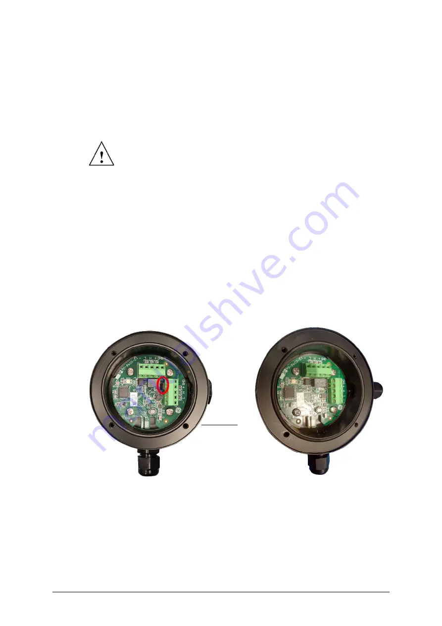
Route the cable from the MMTS(s) to the product cabinet, cutting as required. Figure
9-21 to Figure 9-22 illustrate the terminal connections inside the MMTS. Figure 9-24
shows the CANbus connection inside the cabinet.
Notes:
▪
The shield is connected to the ground of the CANbus terminal block (see Figure 9-24).
▪
It is advisable that the cables are run inside a plastic conduit to provide protection
against mechanical damage.
▪
The cable must be properly inserted into the cable gland. The dome nut of the cable
gland is torqued to a recommended 1.62 N m (14.4 lb in) using a torque wrench.
Figure 9-21: MMTS #1 with jumper
Figure 9-22: MMTS #2/3 without jumper
Ensure that the label number of the MMTS matches the phase / transformer to which it
is mounted. For top oil mappings, refer to Section 10.1 General Settings in ‘MA
-040
–
DGA 900 Plus
–
Operator
Guide’.
At installation, the MMTS should be oriented with the cable gland pointing
down as shown in Figure 9-19. This will minimise the risk of water ingress
to the sensors.
Terminal Key
1
(SHD)
Shield
2
(
+
) 12 V DC (red)
3
(
H
) CANH (green)
4
(
L
) CANL (white)
5
(
-
) Ground (black)
5 4 3 2 1
1
2
3
4
5
5 4 3 2 1


