MA-041
–
DGA 900 Plus - Installation & Commissioning Manual - Rev 1.1
4-Mar-22
Page 78 of 99
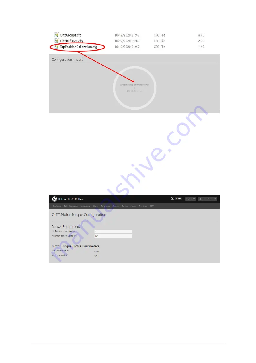
Figure 10-8: Configuration Import
–
TapPositionCalibration.cfg
Use the product’s HMI to verify the sensor parameters and m
otor torque profile
parameters. Select
Models > OLTC Motor Torque Configuration
and ensure that all
parameters, for example as shown in Figure 10-9, match those as given by the
manufacturer of the torque converter.
Sensor Parameters
, ‘Minimum Sensor Value’ and ‘Maximum Sensor Value’
must match
those of the torque converter (0, 2000 by default). Motor Torque Profile Parameters
must be set according to the OLTC Motor nominal power:
‘
Start Threshold
’
to be twice
the nominal power and
‘
End Threshold
’
to be a tenth of the nominal power, e.g. for a 300
W motor, the
‘
Start Threshold
’
should be 600 W and the
‘
End Threshold
’
should be 30 W.
In any case,
‘
Start Threshold
’
must be less than the
‘
Maximum Sensor Value
’
, and the
‘
End Threshold
’
must be greater than the
‘
Minimum Sensor Value
’
.
Figure 10-9: OLTC Motor Torque Configuration - parameters
10.3.2.2
Create Tap Positions
Follow these steps to establish a baseline of tap positions by sequencing the motor
torque outputs to arrive at the desired tap positions:
1.
Move the tap changer to its lowest position.
2.
Increase the tap changer position by
one
(i.e. to the next higher position).
3.
Decrease the tap changer position by
one
(i.e. returning it to the lowest position).


