background image

Chapter 2: Safety and Regulatory

Definium AMX 700 X-Ray System

5161515-1EN

Rev. 6 (10 February 2008)

2-6

Operator Manual

© 2008 General Electric Company. All rights reserved.

• Under most conditions, cumulative radiation dose to the operator will not exceed recommended 

maximum permissible levels. However, as with all radiation-producing devices, a qualified radiation 
expert should evaluate situations involving frequent exposures using high kVp and mAs technics to 
determine if extra protective devices are necessary.

IEC 60601-1 Classifications

• Type of protection against electric shock: Class I, Internally Powered
• Degree of protection against electric shock: Type B Applied Part
• Degree of protection against ingress of water: Ordinary
• Mode of operation: Continuous

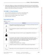
Applicable Symbols

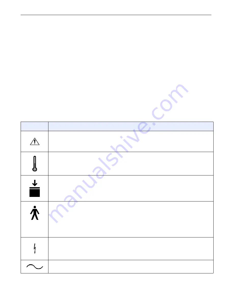
Table 2-1 

Symbols

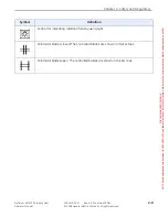
Symbol

Definition

This symbol on the equipment means that the accompanying operating instructions 

should be consulted to assure safe operation.

Store and operate the detector within the range of 0° to 50°C (32°-122°F) to avoid 

damage.

To avoid damage do not place a load in excess of 160kg (350lb) on the detector.

In accordance with UL 60601-1, the Definium AMX 700, is classified as Type B 

Equipment, Class I Equipment, Internally Powered Equipment, Ordinary Equipment 

and continuous operation. Type B Equipment provides an adequate degree of 

protection against electric shock, in particular regarding: 
• allowable leakage current, 
• reliability of the protective earth connection

Dangerous voltage. Indicates an avoidable dangerous high voltage hazard.

Alternating Current. Indicates equipment that is suitable for alternating current only.

FOR 

TRAINING 

PURPOSES 

ONLY! 

NOTE: 

Once 

downloaded, 

this 

document 

is 

UNCONTROLLED, 

and 

therefore 

may 

not 

be 

the 

latest 

revision. 

Always 

confirm 

revision 

status 

against 

validated 

source 

(ie 

CDL).
Summary of Contents for Definium AMX 700

Page 1: ...Rev 6 10 February 2008 2008 General Electric Company All rights reserved FOR TRAINING PURPOSES ONLY NOTE Once downloaded this document is UNCONTROLLED and therefore may not be the latest revision Alwa...

Page 2: ...C 60601 1 Classifications 2 6 Applicable Symbols 2 6 Chapter 3 Hardware Overview Unit Features 3 1 Control and Display Panel 3 5 Hand Switch 3 6 TechSwitch 3 7 Test the Battery 3 9 Replace Transmitter...

Page 3: ...Chapter 7 Maintenance and Service Cleaning the Unit 7 1 Periodic Maintenance by Service Personnel 7 1 Qualified Service Available 7 2 Maintenance Schedule 7 2 Chapter 8 Messages on Display Appendix A...

Page 4: ...Log Off A2 7 Wireless Network Connection A2 7 Software Reset A2 8 System Reset A2 9 Lead Markers A2 9 System Status and Messages A2 10 Expose Hold A2 10 System Status Area A2 10 Message Log A2 11 A3...

Page 5: ...Images to View A5 5 Change Image Display A5 6 Adjust Images A5 7 Annotate and Mask Images A5 9 Customize System Annotations A5 12 Add Image Annotations A5 13 Delete Image Annotations A5 15 Adjust Ima...

Page 6: ...rences System A7 2 Network Connections A7 2 Add or Edit Network Host A7 3 Remove Network Host A7 6 Perform C Echo Test A7 7 Printers A7 7 Add or Edit DICOM Printers A7 8 Remove DICOM Printer A7 12 Wor...

Page 7: ...Protocol Database A7 41 Add or Edit Category A7 42 Add or Edit Exam A7 43 Add or Edit View A7 44 Protocol Editor Copy Functions A7 49 Copy Category A7 49 Copy Exam A7 50 Copy View A7 50 A8 Quality Ass...

Page 8: ...ups B 4 Assign Privileges to Groups B 5 Remove Groups B 5 Show Protected Groups B 5 Working with Users B 7 Add Users B 7 Assign Users to Groups B 8 Change User Password B 8 Remove Users B 9 Show Prote...

Page 9: ...ke changes in the content of it without notify any person of such revision or changes European registered place of business GE Medical Systems Europe Quality Assurance Manager BP 34 F 78533 BUC CEDEX...

Page 10: ...United States address GE Healthcare 3000 N Grandview Ave Waukesha WI 53188 1696 US Phone number United States 262 544 3011 International 1 262 544 3011 Web address www gehealthcare com FOR TRAINING P...

Page 11: ...ower Circuit Breaker information from the Maintenance and Service chapter Figure 6 5 replaced 7 1 Switched order of Maintenance and Messages chapters 7 2 Updated descriptions of Battery Too Low and Ch...

Page 12: ...and wireless network connection status rows to table A6 1 A7 7 Added wireless network connection trouble shooting steps to Failed C echo Test A7 30 Updated steps 2 4 A7 32 Added Enable or Disable Tec...

Page 13: ...A7 50 Removed Unpaired as an option for Laterality B 13 Changed text in table B 1 row Inactivity Timeout Added that this function is not implemented and that changing the settings may cause conflicts...

Page 14: ...table A8 1 removed information about testing factors A8 5 14 Replaced all figures with new images A8 11 Corrected failed QAP information A8 14 Removed most text from Cleaning section and replaced it w...

Page 15: ...the same quality as a full scale x ray room Figure 1 1 Definium AMX 700 in use Safety Information Please refer to Chapter 2 Safety and Regulatory in this Learning and Reference Guide The Safety chapt...

Page 16: ...or radial buttons Choosing an option from a drop down list Activating a tab Highlighting text Highlighting row items Press START EXAM Pressing a button on a workstation screen In the Matrix text box T...

Page 17: ...ING Warning is used to identify conditions or actions for which a specific hazard is known to exist which may cause severe personal injury death or substantial property damage if the instructions are...

Page 18: ...orates a high degree of protection against x radiation other than the useful beam no practical design of equipment can provide complete protection Nor can any practical design compel the operator to t...

Page 19: ...d exposure switch at not less than 2 meters from the focal spot and the x ray beam The full extended spiral cable length of the hand switch is approximately 4 meters CAUTION The x ray beam may extend...

Page 20: ...uency interference to other medical and non medical devices and radio communications To provide reasonable protection against such interference the Definium AMX 700complieswithemissionslimitsforaGroup...

Page 21: ...d by authorized personnel only WARNING Electric shock hazard To prevent possible electric shock do not insert fingers inside the RJ 45 connector Ethernet port Refer to Chapter 3 Hardware Overview Unit...

Page 22: ...omagnetic interference affecting or caused by the unit call service Portable and mobile RF communications equipment can affect medical electrical equipment CAUTION This equipment is not rated for use...

Page 23: ...finition This symbol on the equipment means that the accompanying operating instructions should be consulted to assure safe operation Store and operate the detector within the range of 0 to 50 C 32 12...

Page 24: ...off This does not remove mains voltage Battery power on This does not apply mains voltage Indicates radiographic control Indicates non ionizing radiation is present Indicates ionizing radiation is pre...

Page 25: ...ing radiation field by using light Collimator blades closed The controlled blades are shown in thicker lines Collimator blades open The controlled blades are shown in thicker lines Symbol Definition F...

Page 26: ...700 easily adapted to operating intensive care and emergency room applications Because of a dual motor drive driving and positioning the Definium AMX 700 requires minimum effort And the control panel...

Page 27: ...h mechanism Locks the tube head down during transport Refer to Chapter 4 Moving and Positioning Latch Lock Release p 4 5 for more information 5 Wireless antenna Connects the unit to the facility netwo...

Page 28: ...es or errors Refer to Control and Display Panel p 3 5 for more information 11 Hand switch for initiating exposures Refer to Hand Switch p 3 6 for more information NOTE Some models may have a wireless...

Page 29: ...he exam Refer to Chapter A4 Image Acquisition Conduct a Cassette Exam p A4 10 for more information 16 Front wheels 17 Detector tether holder Provides a place to wrap the tether cord during transport o...

Page 30: ...ttery charging cord The cord retracts into the body when moving Refer to Chapter 6 Charging the Batteries for more information 21 Main power circuit breaker Refer to Chapter 6 Charging the Batteries M...

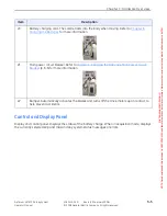
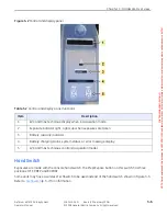
Page 31: ...y have a wireless TechSwitch to be used instead of the hand switch shown in Figure 3 3 Refer to TechSwitch p 3 7 for information Item Description 1 kVp and mAs technique display when in acquisition mo...

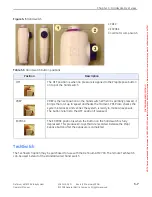
Page 32: ...the Prep Expose button on top of the hand switch PREP PREP is the next position on the hand switch When it is partially pressed it brings the rotor up to speed and heats the filament PREP also checks...

Page 33: ...mitter at the infrared remote sensor 4 To turn on the collimator lamp press the Field Light button on the transmitter optional function 5 To PREP press and release the Prep Expose button on the transm...

Page 34: ...s reliably at this range If not a new battery is required This test should be performed quarterly or when a transmitter battery problem is suspected Replace Transmitter Battery Remove the six screws f...

Page 35: ...ewing Backing up the protocol database or other system data The CD drive connects to the unit through a USB port Plug in the CD drive power supply and insert the connection cable into any USB port NOT...

Page 36: ...stics self tests to make sure everything is working correctly This process takes a few seconds 2 When the technique and battery status displays light up the unit is ready for operation TESTING COMPLET...

Page 37: ...nit to your destination Figure 4 2 Drive handle WARNING Movement of the Definium AMX 700 x ray unit could cause the horizontal arm to slide and strike an operator or patient if not latched properly La...

Page 38: ...ng and maneuvering easily for exact positioning Again grip the drive handle and turn the unit to the desired position Definium AMX 700 maneuvering speed is automatically reduced by 50 percent when the...

Page 39: ...00 to make it go faster it may stop and display the message RELEASE HANDLE If this happens release the handle to clear the message and then continue with normal operation 7 To stop the unit and activa...

Page 40: ...p Follow these steps to release the latch vertical column and telescoping arm locks from the park transport position Make sure that the unit is turned ON Latch Lock Release 1 Grip the collimator handl...

Page 41: ...mend that you use the lock release system IMPORTANT Remove the tether from the holder before rotating the column 1 Rotate the arm and vertical column assembly to horizontally position the telescoping...

Page 42: ...o activate the high intensity field lamp The cross hair beam shows the field center The field light is timed and automatically turns off 30 seconds after you release the switch To adjust the field lig...

Page 43: ...he field size for a selected SID Dial numbers on the calibrated scale are for a 40 inch 100 cm and 72 inch 180 cm scale SIDs Figure 4 10 Collimator controls 5 You may rotate the collimator about its v...

Page 44: ...3 Shield and collimate as appropriate 4 Select the procedure from the Worklist Refer to Appendix A GE Portable DR Detector Operating Instructions Chapter A3 Worklist for more information 5 Select the...

Page 45: ...f an exposure has occurred 10 Secure the unit for transport when the exam is complete 11 Park tube and detector Technique Adjustment The software provided with the GE Portable DR Detector contains the...

Page 46: ...n the message display to alert you IMPORTANT Carefully check the digital display Figure 5 1 before making an exposure to ensure that thefactorsselectedarethosethatareintended Payparticularattentiontot...

Page 47: ...ings stated within this operation manual and as allowed by the equipment may appear to exceed the tube ratings The reason for this apparent discrepancy is that the tube rating charts in Product Data S...

Page 48: ...ically performs an extended charge to make sure that all portions of the battery s internal plates get fully charged This extended charge occurs every tenth 10th time the battery is charged To recharg...

Page 49: ...n back on After it has completed its power up tests the Definium AMX 700 will provide enough capacity for approximately 45 seconds of usage before x ray exposures are again inhibited CAUTION In some c...

Page 50: ...um AMX 700 operating modes in a relative basis Figure 6 2 Battery drain As Figure 6 2 demonstrates the majority of the battery pack s capacity is used for drive and idle Thus reducing the amount of dr...

Page 51: ...a designated battery charging station or to a correctly rated wall outlet Position the unit to within 10 feet of the outlet 2 To plug in firmly grip the plug located on the front of the unit Figure 6...

Page 52: ...ndicator bars are illuminated 5 Unplug the unit from the outlet giving the plug a slight tug to release from take up reel IMPORTANT After unplugging the unit turn the unit on and wait approximately 15...

Page 53: ...tion If necessary recharge the unit or if the battery is adequately charged try the procedure again If the battery is within operating condition as indicated by the battery status and message displays...

Page 54: ...cleaning the Definium AMX 700 and GE Portable DR Detector Cidex OPA Gigasept FF T Spray Inciden Plus Perasafe Ster Bac Blue Super Sani Cloth Germicidal Wipes TriGene Isopropyl Alcohol 70 maximum solut...

Page 55: ...519 200 Collimator general inspection and adjustment Every year Refer to Service Documentation CD ROM 5161519 200 Filament and rotor interlocks Every year Refer to Service Documentation CD ROM 5161519...

Page 56: ...age wear etc Every year Refer to GE Portable DR Detector PM Schedule Inspect PC shock mounts for damage wear Every year Refer to GE Portable DR Detector PM Schedule Verify the PC is still mounted secu...

Page 57: ...Electric Company All rights reserved Table 7 2 Sample chart for technique accuracy tests Technique Selected mAs kVp Primary Volts kVp Time Sec FOR TRAINING PURPOSES ONLY NOTE Once downloaded this doc...

Page 58: ...the function again If the problem is corrected and no error message is displayed proceed as usual 2 If the error message still displays turn the unit OFF then back ON Diagnostics or self tests are qu...

Page 59: ...unit is plugged in CHARGING The unit is charging DRIVES ONLY All modes are disabled except drive Service is required HEAT WAIT No exposures can be taken while this message appears The length of the de...

Page 60: ...but not enabled For Example The ON light is flashing on the Automatic Exposure Control AEC unit This indicates the paddle is not connected Reset the AEC controller The red reset GEN on the Automatic E...

Page 61: ...ing loaded Wait for system to boot completely SHUTTING DOWN System PC is shutting down GOOD BYE System PC has shut down NO DIG RESPONSE Digital Radiography components are not responding TURN OFF SWITC...

Page 62: ...ist describes the process of adding procedures to and selecting procedures from the Worklist screen to begin exams Chapter A4 Image Acquisition describes the process of performing exams Chapter A5 Ima...

Page 63: ...p A1 3 Nameplates and Markings p A1 3 Detector Safety Labels p A1 4 Use p A1 5 Detector Alignment p A1 5 Indicator LEDs p A1 5 Electro magnetic Interference p A1 6 Detector Grid p A1 7 Grid Attachmen...

Page 64: ...ach pixel is attached to a data acquisition circuit that converts incoming x ray signal to 14 bit digital data The detector is constructed from a metal case The front face contains a graphite x ray im...

Page 65: ...tronics is to convert the charge into digital image data This data is then transmitted to the system workstation through an ethernet connection Physical Appearance Finish The detector unit is designed...

Page 66: ...ccompanying documents CAUTION Do Not Drop CAUTION Device weighs 5 89kg 13 lbs CAUTION Do Not Use a defibrillator while patient remains in contact with detector 2 Type B Applied Part 3 Maximum load CAU...

Page 67: ...crubs This LED indicates Ready to Image status Table A1 1 shows a list of conditions and how they are communicated by the LED lights Table A1 1 Detector status lights Condition Green LED Red LED Indic...

Page 68: ...G field strengths which can cause artifacts on x ray images EM fields are reduced by the square of the distance between the EM source and the detector Thus moving the EM source twice as far away will...

Page 69: ...or so that the detector LED lights show through the holes in the grid holder Grid Attachment The bottom edge of the detector should be placed into the bottom lip of the grid holder while held in the v...

Page 70: ...the detector Do not use the detector as a stretcher to lift a patient Do not drop the detector at any time Do not prop the device on an edge against wall or bed Keep detector in cradle bucky or other...

Page 71: ...not step on the tether Do not run over the tether with the unit cart table or other equipment Do not use the tether as a handle Do not bend or fold the tether sharply especially at the points where t...

Page 72: ...or grid for more than 60 seconds Let the detector dry at least 60 seconds between cleanings The following chemicals and products have been tested and approved by GE for cleaning the GE Portable DR De...

Page 73: ...e tether or grid 6 kg Tether The detector interfaces with the external controller via one tether cable that contains 2 connections communication interface with external controller and power interface...

Page 74: ...ectrum exceeding the following parameters Type Random Frequency Range 20 to 350 Hz Magnitude 0 006g2 Hz at 10 350 Hz Duration 8 hours axis x y z The detector assembly shall not be exposed to non opera...

Page 75: ...bile systems International Language Configuration p A2 3 Software Start Up and Shutdown p A2 4 Start Up p A2 4 Shutdown p A2 4 Login and Log off p A2 5 Invalid Password Message p A2 6 Emergency Login...

Page 76: ...box on a screen The virtual keyboard appears 2 Type letters and numbers as appropriate for the text box Letters and numbers appear in the box at the top of the screen as they are pressed a To correct...

Page 77: ...eyboard will function similarly to a physical keyboard for that country Figure A2 2 The keyboard will provide access to these special characters through use of the SHIFT key and the AltGr key The keyb...

Page 78: ...he unit is ready for operation TESTING COMPLETE will also briefly appear on the message display The unit may take 3 minutes for the digital detector software to boot up You may drive the unit before t...

Page 79: ...the system is configured for Login ability in the Service User Interface Refer to Appendix B Login Administration for information on administering the login function Standard Login The Login screen F...

Page 80: ...e sensitive That is aBc is not the same Login Name as Abc 2 Retype your Password carefully Your password is case sensitive that is xYz is not the same password as Xyz 3 Press LOGON Contact your techni...

Page 81: ...and returns you to the last screen Wireless Network Connection Wireless is a purchasable option that allows the unit to connect to the facility wireless network without the cable This allows you to up...

Page 82: ...ireless connection if the cable is not connected if the cable is connected the unit will choose the wired connection NOTE Software reset does not require Shutdown or a System Reset Follow this process...

Page 83: ...appears As the system resets various screens will appear on the monitor This is normal The system will auto start and either the Login screen or Worklist screen will appear depending on how your syst...

Page 84: ...they are corrected The Expose Hold button disappears when all errors and interlocks are corrected Figure A2 8 Worklist and Acquisition screen Expose Hold button Figure A2 9 Example system Inhibits li...

Page 85: ...Log Figure A2 11 The Message Log shows all status messages since the last system restart The messages are listed in descending chronological order that is the latest message is listed first This scree...

Page 86: ...rge table made of columns and rows Each row in the list is a procedure or exam to be performed A patient may have multiple procedures rows on the Worklist Procedures listed can be classified under two...

Page 87: ...ws you to change between the Worklist Image Management and Utilities screens or allows you to logoff the system if applicable The darker color indicates which screen is currently displayed The individ...

Page 88: ...For mobile units Search is only available when the unit is connected to the network Refer to Search p A3 7 for more information KEYBOARD Brings up the virtual keyboard so that you may type text into...

Page 89: ...to Add Edit Patient Information p A3 15 for more information ADD PATIENT Allows you to enter patient information and adds the patient to the Patient List Refer to Add Edit Patient Information p A3 15...

Page 90: ...and signal strength Refer to Chapter A2 General Information Wireless Network Connection p A2 7 for more information system status Displays the last system status message To clear the system status are...

Page 91: ...ption The procedure ordered for the accession number This is the content of the Procedure Description field on the Add Information screen Physician The name of the physician or technician who performe...

Page 92: ...efer to Chapter A2 General Information Virtual Keyboard p A2 2 for information on how to use the virtual keyboard to type information into a text box The list automatically goes to the first procedure...

Page 93: ...only display items corresponding to your chosen criteria e g exams taken only within a specified time period patients whose last names begin with the letter J or patient IDs beginning with the digits...

Page 94: ...ms in the filter Date Allows you to select the date of exams to filter by All procedures scheduled for any date Range procedures scheduled for a specified range of time Today procedures scheduled for...

Page 95: ...endar closes automatically when a date is clicked 6 Enter any Patient Information you want to filter by You do not need to enter full words or numbers into these text boxes Entering more information i...

Page 96: ...efresh Follow this process to manually refresh the Worklist 1 Press REFRESH on the Worklist The Worklist updates with HIS RIS data and removes any filtering NOTE Refresh does not remove locally added...

Page 97: ...o begin image acquisition NOTE The Patient Name Patient ID and Exam Date must match exactly in order to be selected 1 Sort the Worklist by Patient Name if necessary 2 Press procedure 3 Press another p...

Page 98: ...ch the button to DELETE A message appears Are you sure that you would like to delete the selected items 3 Press OK to delete the procedures CANCEL retains the procedures and the Worklist appears Delet...

Page 99: ...iscontinued and proceed with deletion 2 Press COMPLETE or DISCONTINUE COMPLETE changes the Status to of the procedures to Completed If enabled any acquired images are auto pushed auto printed and sent...

Page 100: ...en To view the patient information from the Worklist or Image Management screens select the exam then press PATIENT INFORMATION Patient information is not editable when launched from the Image Managem...

Page 101: ...st be unique Gender Defines the sex of the patient By default Other is selected when the screen first opens Birth Date Identifies the patient s birthday in the format dd mm yyyy If the date is not ent...

Page 102: ...formation screen Completed exams are sent to the PACS where available Discontinued The procedure was opened but no exposures were taken The exam may be started at a later time or the procedure deleted...

Page 103: ...and begin Acquisition Press CANCEL to close the Add Patient screen without saving changes NOTE For a new exam on a existing patient the patient information cannot be edited SAVE Adds the patient to th...

Page 104: ...e procedures are selected the PATIENT INFORMATION button is disabled 1 Select the procedure from the Worklist 2 Press PATIENT INFORMATION The Patient Information screen appears 3 Edit the information...

Page 105: ...Emergency Exam p A4 12 End Exam p A4 13 Suspend p A4 13 Close p A4 14 Discontinue p A4 14 Overview The Acquisition screen Figure A4 1 is where the exam is set up and exposure details are adjusted Thi...

Page 106: ...ENT INFORMATION Displays Patient Information screen for the current procedure Refer to Chapter A3 Worklist Add Edit Patient Information p A3 15 for more information screen switch tab Switches between...

Page 107: ...ols screen to add remove or change protocols Refer to Select or Change Protocols p A4 7 for more information SUSPEND Ends the exam with the intent of continuing at a later time Does not initiate auto...

Page 108: ...receptor for the protocol In order from left to right the options are Free Cassette GE Portable DR Detector NOTE The generator limits exposure time to two 2 seconds for both receptors Reset Technique...

Page 109: ...lays the recommended patient position relative to the detector network connection status Appears when the Definium AMX 700 is connected to the hospital network wireless network connection status If th...

Page 110: ...APPEND EXAM creates a new series within the existing exam and opens the Select Protocols screen QAP When the yellow alert icon is present indicates that QAP should be performed to ensure continued im...

Page 111: ...Protocols must be reselected and techniques must be re set Select or Change Protocols The Select Protocols screen Figure A4 3 appears when you press START EXAM on the Worklist or Add Patient screen o...

Page 112: ...to show the available exams Press on the anatomical category name again to close it 3 Press on an exam to select it A checkmark appears in the box to the left of the exam name A checkmark appears nex...

Page 113: ...ou will be returned to the Worklist 1 If multiple procedures were selected from the Worklist select the procedure from the exam drop down list 2 Select the Exam and View to perform from the protocol l...

Page 114: ...10 Have the patient suspend respiration if required 11 Make exposure using the hand switch or TechSwitch The image appears on Image Viewer screen NOTE It takes about 9 seconds for a fully processed im...

Page 115: ...reselect the view you wish to perform as shown in step 4 be low recommended Remove the detector from the bin for the duration of the exam Refer to Chapter 3 Hardware Overview Unit Features p 3 1 for m...

Page 116: ...te and shield as appropriate for the exam 8 Have the patient suspend respiration if required 9 Make exposure using the hand switch 10 Press CLOSE to end the exam The Worklist appears 11 Process the ca...

Page 117: ...mergency exam 1 Press EMERGENCY EXAM from the bottom left of the Worklist The Select Protocols screen appears Refer to Select or Change Protocols p A4 7 for more information 2 Select the protocols for...

Page 118: ...ocedure to discontinue an exam 1 Press DISCONTINUE from the bottom of the Acquisition screen A message appears Please select a reason for discontinuing this exam 2 Select the option that best describe...

Page 119: ...ken DEI p A5 18 Change Pointer Controls p A5 21 Apply Quality Check Indicator Auto Tag p A5 22 Print Images p A5 22 Send Images p A5 27 Save Changes to Images p A5 27 Overview The Viewer shows all ima...

Page 120: ...e Patient Information screen screen switch tab If in an active exam allows you to switch back to the Acquisition screen If viewing images from a completed exam the Acquisition screen tab is disabled N...

Page 121: ...adjust contrast invert and apply windowing to images Refer to Adjust Images p A5 7 Annotations Mask Contains the tools to annotate and crop images Refer to Annotate and Mask Images p A5 9 Reprocessing...

Page 122: ...mages are currently saved to the local database and approximately how many more images the database can accommodate system status Displays the last system status message NOTE To clear the system statu...

Page 123: ...xam always work with processed images The top half of the tool panel shows the different exams and series that are available When you select a series previews or thumbnails of all the images within th...

Page 124: ...o 9 images at one time Figure A5 4 Format Zoom panel Table A5 2 Zoom tool descriptions Tool Description Zoom One Shows default the image size where one pixel on the detector equals one pixel on the sc...

Page 125: ...mage Display Tools descriptions Tool Description Contrast Adjusts the differences between dark and light on the selected image Move the slider right for more contrast towards pure black and white Move...

Page 126: ...e 180 degrees on the horizontal axis that is switches top for bottom Horizontal Flip Flips the selected image 180 degrees on the vertical axis that is switches left for right Rotate Left Rotates the s...

Page 127: ...tations are displayed as text at the corners of the image You may select which annotations appear but you cannot control where the annotations are placed Figure A5 6 Annotations Mask panel Table A5 4...

Page 128: ...tes the selected image annotation NOTE Deleted annotations cannot be recovered Erase All Deletes all image annotations NOTE Deleted annotations cannot be recovered RL Places a Right or Left marker on...

Page 129: ...e measurements for line ellipse and Cobb annotations Display parameters bottom right corner the size of the image and the zoom Partial Displays ONLY the facility name dose information and technical fa...

Page 130: ...ssary 2 Press CUSTOM The Annotation screen Figure A5 7 appears Figure A5 7 Custom Annotation selections 3 Select check the annotations you want to appear 4 Adjust the Font Size if necessary The availa...

Page 131: ...ngle of the annotation as described in Table A5 5 NOTE When resizing annotations make sure that the pointer arrow is inside the square handle and has changed to a sign Figure A5 8 before trying to mov...

Page 132: ...n screen Type your comment Press OK To move Press and drag by the red square on the top left corner of the text box To edit Double tap two touches in quick succession the User Annotation Make your cha...

Page 133: ...formation The Manual Shutter function allows you adjust the automatically applied default shutter for viewing and printing You can only adjust the shutter of images in an active exam or of re processe...

Page 134: ...the adjustment If the image does not return to its selected size click the Zoom buttons on the Viewer Display panel to re select the viewing size Refer to Change Image Display p A5 6 for more informa...

Page 135: ...an exam or closing patient in review mode you must select to save changes to images or the re processed images will not remain in the series Refer to Save Changes to Images p A5 27 for more informati...

Page 136: ...ay of the Detector Exposure Index and the DEI ranges are configured from the Image Viewer preferences screen Refer to Chapter A7 Set Preferences DEI Detector Exposure Index p A7 28 for more informatio...

Page 137: ...hen an exposure taken of the same object assuming identical technique and positioning after setting the speed to 200 will also give a DEI of 1 72 NOTE A higher DEI indicates a higher exposure to the d...

Page 138: ...individual images or Chapter A7 Set Preferences Image Processing p A7 31 to change the default processing for exams and views NOTE Call for service if the system continues to show low or high DEI Rec...

Page 139: ...upon This is the default pointer behavior Pan Image Moves the image within the viewing area Image Magnifying Glass Shows a small part of the image at 3 times magnification Change Image Brightness Cont...

Page 140: ...so that the T disappears To restore the quality check indicator press the white box so that the T reappears Figure A5 17 Quality check indicator Print Images Images can be printed from the system in...

Page 141: ...are more images in the series than will fit on the sheet use the Sheet and buttons to configure the printing options for each sheet NOTE You are able to change the number of images for each sheet indi...

Page 142: ...e A5 8 for more information 6 Press CLOSE when finished Print Current Image Follow this process to print a single image 1 Select the image from the Images tool palette if necessary 2 Press MANUAL PRIN...

Page 143: ...r horizontal orientation of the image on film or paper Available options are Landscape Portrait Print Mode Selects what size to print the image Available options are True Size Fit to Film Reduce Size...

Page 144: ...ects the magnification type Available options are Cubic None Annotation Selects the amount of annotation to print on the image Available options are Full Partial Custom None Refer to Annotate and Mask...

Page 145: ...the unit is connected to the network Save Changes to Images You have the option to save or discard the changes you have made to images when you close the Image Viewer screen or end the exam 1 If in a...

Page 146: ...Each exam is a row If multiple exams were acquired in the same session each exam has its own row on the list The exam expands to show the series Within each exam are series of images A series is a co...

Page 147: ...6 1 Image Management screen Table A6 1 Image Management screen functions 1 Selected exam 2 Series in exam 3 Image detail button 4 Images in selected series 5 Preview of selected image Function Descrip...

Page 148: ...to Chapter A7 Set Preferences for more information LOG OFF If the Login function is enabled pressing this button logs the current user off of the system Refer to Chapter A2 General Information Login a...

Page 149: ...play monitor NOTE ItisnotexpectedthatyouwillneedtoaccesstheSMPTEpattern or test images during the course of normal work Test images are used to calibrate the system or to determine the cause of image...

Page 150: ...the unit s external CD drive is connected Refer to Copy Exams and Images p A6 9 for more information DELETE Deletes the selected exams series or images from the local database Refer to Delete Exams Se...

Page 151: ...ges to another database or disk Delete Exams Series or Images p A6 13 to remove images system status Displays the last system status message Refer to Chapter A2 General Information System Status and M...

Page 152: ...on a CD 1 Connect the external CD R W drive to the unit 2 Insert the CD with images into the CD drive 3 Press Source CD1 The exam list updates to show the images stored on the CD 4 Select the exams 5...

Page 153: ...1 Press the button on the Search By drop down list to select the column you want to search If the column you want is already selected begin at step 3 2 Select the column For example Patient ID The li...

Page 154: ...ges for viewing 1 Press the button to the left of the exam name to open it The series for the exam expands below the exam 2 Press the series to open it or select the series and press to see image deta...

Page 155: ...Images to Another Exam This process is used to copy images from one exam to another Copying images is used to consolidate images from multiple exams to a single exam and to reconcile patients to exam...

Page 156: ...py Exam screen shows all Worklist entries with the status of Scheduled Discontinued or Suspended 4 Search or Filter the exam list to locate the destination exam 5 Select the exam where you want the im...

Page 157: ...the CD Always use a new blank CD 1 Open the CD tray Select Eject from the CD1 drop down list NOTE Pressing the Eject button on the workstation PC does not open the CD tray When working on the Image M...

Page 158: ...e CD 10 Label the CD and store in a safe place Delete Exams Series or Images Exams series and images may be deleted from the local database from the Image Management screen Follow this process to dele...

Page 159: ...he locked exams The Unlock button becomes active 2 Press UNLOCK The lock icon is removed from the status column of the selected exams The exams may now be deleted NOTE You are able to lock or unlock m...

Page 160: ...ocess to make exam images anonymous 1 Select the exams to make anonymous 2 Switch the Image Tools button to DE IDENTIFY if necessary A message appears The selected exams will be copied without patient...

Page 161: ...recall Topics covered include Preferences are set on the Utilities screen Figure A7 1 which is accessed by pressing the UTILITIES button on the Worklist System p A7 2 Network Connections p A7 2 Print...

Page 162: ...Connections Network and printer connections are configured through the Utilities System System screen This screen allows qualified service personnel to define the Digital Imaging and COmmunication in...

Page 163: ...Figure A7 3 and Figure A7 4 Table A7 1 and Table A7 2 describe the fields in detail If editing an existing connection select the network host and press EDIT If adding a new connection press ADD 1 Comp...

Page 164: ...cores _ to separate words Application Entry Title The DICOM application title IP Address The IP address of the network host Port Number The port number for the network host Query Retrieve Sets the typ...

Page 165: ...Portable DR Detector system name Allows this host to open and display exams from the GE Portable DR Detectorsystem Allow this host to send images to the GE Portable DR Detector system name Allows the...

Page 166: ...he Acquisition workstation Send MPPS N Create and N Set notification to this network host This node acts as the Destination for receiving the MPPS N Create N Set Notification When configured for MPPS...

Page 167: ...unit is connected to the network Try connecting the unit to a different network port There may be a problem with the port itself For units with wireless connection Check the signal strength Remove an...

Page 168: ...A7 8 Table A7 3 Table A7 4 and Table A7 5 describe the fields in detail 1 If Editing an existing printer s configuration select the printer from the DICOM Printers list and press EDIT If adding a new...

Page 169: ...nderscores _ to separate words Application Entry Title The DICOM application title Network Address The IP address of the printer Port Number The port number of the printer Pixel Depth The resolution o...

Page 170: ...m or not Polarity Available options are Normal Reverse Border Density Sets the color of the image border Available options are Black White Empty Image Density Sets the color of areas that have no imag...

Page 171: ...the page for example 2 images per page may be side by side or one on top of the other Slide formats Selections allow the side formats available for the printer if any Function Description Film sizes...

Page 172: ...onnections screen select the printer 2 Press REMOVE A message appears Are you sure you want to remove printer name 3 Press YES CANCEL closes the message and returns you to the Network Connections scre...

Page 173: ...orklist screen Default Query The Worklist Default Query controls the amount of HIS RIS information that appears on the Worklist and allows you to enable and configure the auto refresh function 1 Compl...

Page 174: ...s the date range of scheduled procedures to show on the Worklist Available options are All Current Day Plus previous __ Days __ Hours Shows procedures that are scheduled for the specified time before...

Page 175: ...t Names The Preset Names screen Figure A7 12 allows you to add remove or edit the names that appear on the Add Patient Patient Information screen s Operators Performing Physicians and Referring Physic...

Page 176: ...Add Preset Names 1 Press ADD for the appropriate group 2 Type the name to add 3 Press ADD Edit Preset Names 1 Select the name to change 2 Press EDIT for the group 3 Edit the name as appropriate 4 Pre...

Page 177: ...y All rights reserved Remove Preset Names 1 Select the name to remove 2 Press REMOVE for the group 3 Press OK to remove the name Press NO to keep the name FOR TRAINING PURPOSES ONLY NOTE Once download...

Page 178: ...exams to be copied between the local databases and network hosts It also allows exams to be copied to a CD There is no configuration for this function it is either enabled ON or disabled OFF Follow th...

Page 179: ...4 Press CLOSE Auto Print Default Print Auto Print Figure A7 14 allows you to configure your printer parameters This is done so that you do not need to select all the parameters each time you print an...

Page 180: ...tation Landscape horizontal film orientation Print Mode Provides options on the size of the image data printed Available options are True Size Fit to Film Reduce Size Orthopedic Magnification if enabl...

Page 181: ...llows you to choose the destinations available for the selected printer Available options are Magazine Processor Magnification Type Allows you to choose the magnification types available for the selec...

Page 182: ...The Auto Send screen appears 4 Complete the information as described in Table A7 8 5 When finished press SAVE to retain your changes Figure A7 15 Auto Send Table A7 8 Auto Send Functions CANCEL Closes...

Page 183: ...s 4 Complete the information as described in Table A7 9 5 When finished press SAVE to retain your changes 6 Press CLOSE Figure A7 16 Auto Delete Auto Send column Allows you to choose which images are...

Page 184: ...ocessed image printed Selecting the Print parameter allows auto deletion of images that have been printed Processed image sent Allows auto deletion of processed images with no errors that have been se...

Page 185: ...nces allow you to add edit or remove pre set annotations Follow this process to configure pre set annotations 1 From the Worklist screen press UTILITIES 2 Select Preferences Viewer 3 Press Pre set Ann...

Page 186: ...it Pre set Annotation p A7 26 or Remove Pre set Annotation p A7 27 7 When finished press SAVE to retain your changes 8 Press CLOSE Add Pre set Annotation 1 From the Pre set Annotations screen press AD...

Page 187: ...e Pre set Annotation 1 From the Pre set Annotations screen select the annotation 2 Press REMOVE A message appears Are you sure you would like to delete the annotation annotation name 3 Press OK FOR TR...

Page 188: ...per limits for anatomical views These settings determine how DEI is displayed for all images Follow this process to change the DEI settings 1 From the Worklist screen press UTILITIES 2 Select Preferen...

Page 189: ...ctor Exposure Index screen press an anatomical category to expand it Press the category again to close it 2 Change the lower and upper limits in the text boxes as appropriate for the view No Display I...

Page 190: ...checkbox Figure A7 21 indicates if Technical Mode is enabled Check or uncheck the box as appropriate and press SAVE to apply the change and close the screen Figure A7 21 Technical Mode checkbox Export...

Page 191: ...at their next visit GE Service personnel can restore the settings from the backup if necessary Figure A7 22 Preferences Image Processing Change Default Factory Looks for Exams The Default Factory Loo...

Page 192: ...the Default Factory Looks screen Figure A7 23 Default Factory Looks Build Custom Looks Looks are the way an image is processed to be viewed by a radiologist for interpretation Looks are pre defined c...

Page 193: ...o posterior or lateral 6 Select the Image Type some systems may only have Standard image type available 7 Select the Patient Size Available options are Small Adult Medium Adult Large Adult Small Pedia...

Page 194: ...ust However forsmall alterations of brightness on a particular image use the Brightness and Contrast controls in the Image Viewer screen Tissue Contrast Controls the general contrast between the thick...

Page 195: ...e reduction feature suppresses the mottle noise in denser areas of the anatomy while preserving detail in the rest of the image The algorithm takes into account tissue penetration and dose reaching th...

Page 196: ...and APPLY TO IMAGE button PREVIEW applies the settings to the currently selected image in the Image Viewer screen so that you can see the effect before saving the changes APPLY TO IMAGE creates a new...

Page 197: ...laying anatomy like the white shoulders Using TE the overlaying anatomy can be made grayer making the underlying spine more visible Figure A7 26 A hand image can similarly be displayed with improved b...

Page 198: ...TE is applied to it For example increasing STRENGTH for under penetrated regions such as shoulders makes a white region grayer Increasing STRENGTH for over penetrated regions such as lungs makes a bl...

Page 199: ...eral contrast between the thick and thin anatomy For example Tissue Contrast can be used in combination with Tissue Equalization to define a Chest PA look that is equalized in the lung fields but with...

Page 200: ...If necessary the old database can be retrieved and used Follow this process to back up the database to a CD NOTE Always use a new blank CD R for each back up DO NOT use re writable CD RW disks The sys...

Page 201: ...lect Preferences Protocols 4 Insert the CD with the saved protocols database into the CD tray 5 Press RETRIEVE A message appears Press OK to continue with Protocol Database retrieve 6 Press OK The sav...

Page 202: ...Protocols 3 Press EDIT The Exam Menu appears 4 Continue with Add or Edit Category p A7 42 Add or Edit Exam p A7 43 or Add or Edit View p A7 44 Figure A7 30 Exam Menu Add or Edit Category NOTE The scr...

Page 203: ...the placement of the new category on the category list 4 Press OK 5 Continue with Add or Edit Exam p A7 43 NOTE Examsand views must be added or copied into the new category in order for itto be fully...

Page 204: ...ulated with new or copied views after creation in order to be fully functional Add or Edit View NOTE The screens and process to edit a view are the same as for adding a view This process has multiple...

Page 205: ...are available 10 Select the Laterality The selected anatomy determines which laterality options are available If the anatomy is unpaired then Unpaired is the only available selection If the anatomy i...

Page 206: ...rs 13 Select all Patient Sizes you want available for the view The default size will automatically be selected 14 Select Receptors and Modes for each selected receptor 15 Select the Default Receptor c...

Page 207: ...ress NEXT The Review screen appears The default patient size is shown with an asterisk to the left of the size indicator 17 Select the patient size to edit 18 Press EDIT TECHNIQUE FOR TRAINING PURPOSE...

Page 208: ...r selects values appropriate for the patient size 20 Upon completion for each view press NEXT TECH adjust techniques for the next configured patient size 21 When finished press EXAM MENU The Exam Menu...

Page 209: ...itor Copy Functions Follow this process to access the Protocol Database Editor 1 From the Worklist select UTILITIES 2 Select Preferences Protocols 3 Press EDIT The Exam Menu appears Figure A7 32 Exam...

Page 210: ...the Exam to copy 2 Press COPY EXAM 3 Enter the new name to use or retype the existing name 4 Select the Category to copy to 5 Select the position on the Exam list 6 Press OK 7 Continue with Copy View...

Page 211: ...xam from the list 6 Select the Position View from the list 7 Press OK NOTE Remember to back up the database when finished editing Refer to Backup Protocol Database to CD p A7 40 for more information F...

Page 212: ...p A8 1 When to Perform Quality Tests p A8 2 Quality Test Preparation p A8 2 Perform Detector Check p A8 3 Perform QAP p A8 5 Result History p A8 11 Maintenance and Cleaning p A8 12 Types of Quality Te...

Page 213: ...hedulingQAPtests plan15 20minutestoperformthetest Oneportionofthetestrequires that the system be powered on and in an idle state i e without exposures for at least 10 minutes The 10 minute idle period...

Page 214: ...on at the bottom of the Worklist or Acquisition screen The Image Quality screen appears Figure A8 2 Image Quality screen 2 Select Quality Control Tests from the left side of the screen Figure A8 3 Fig...

Page 215: ...ETECTOR CHECK The Detector Check Tests screen appears Figure A8 5 Detector Check Tests screen 4 Press START to begin the Detector Check 5 Wait for the test to complete The Detector Check result screen...

Page 216: ...tion and potential calibration are needed WARNING Image quality may be degraded if you continue to use a detector that has failed the Detector Check tests Figure A8 7 Failed Detector Check results Per...

Page 217: ...calibration software These techniques are required for proper calibration and should not be changed by the user Figure A8 8 Flat field phantom Follow this process to perform a QAP test 1 Press the QA...

Page 218: ...dle state without exposures for at least 10 minutes before the Vertical Bar Calibration portion of the test can begin If the system has not been idle a countdown timer appears on the bottom of the scr...

Page 219: ...n a Verify that the detector is out of its holder b Press START and wait for the detector check tests to be completed and results to be displayed The Detector QC Tests screen appears automatically whe...

Page 220: ...Flat field Tests The Flat field tests screen appears 9 Follow the instructions on screen to complete this portion of the test a Do not reposition the system b Prep and expose the flat field phantom Th...

Page 221: ...cedure to confirm the failure Check the items listed below when repeating the tests Check collimator blades Make sure that they are fully open and not in the field of view Check that the phantom is co...

Page 222: ...values test specifications LSL and or USL and pass fail status A minimum of 25 QAP test results are maintained Follow this process to view the results of previous QAP tests 1 From the left pane press...

Page 223: ...he IEC regulations The device is used in accordance with the Operating Instructions Original or authorized spare parts are used If service of the unit is performed the service technician must provide...

Page 224: ...he patient should be cleaned with an EPA registered low level disinfection or sanitizing agent CAUTION In the event of equipment contacting broken skin or being used with infected or immune compromise...

Page 225: ...p B 3 Working with Groups p B 4 Add Groups p B 4 Assign Privileges to Groups p B 5 Remove Groups p B 5 Show Protected Groups p B 5 Working with Users p B 7 Add Users p B 7 Assign Users to Groups p B 8...

Page 226: ...to being able to add procedures to the Worklist conduct exams and manage images Standard and Limited User only allows access to add procedures to the Worklist conduct exams and manage images Groups ar...

Page 227: ...istrator access a message Figure B 1 appears You have both regular user and admin user privileges To access the admin screen select the check box before continuing with the login otherwise just contin...

Page 228: ...es are at the top of the screen columns and the group names are at the left edge of the screen rows Figure B 2 Group and Permissions Mapping tab Add Groups 1 Select the Group and Permissions Mapping t...

Page 229: ...ps and Users p B 2 for definitions of privileges NOTE The Service privilege is protected and cannot be selected Only GE Service personnel can assign a group to the Service privilege 3 Click on a selec...

Page 230: ...2008 B 6 Operator Manual 2008 General Electric Company All rights reserved Figure B 4 Protected groups FOR TRAINING PURPOSES ONLY NOTE Once downloaded this document is UNCONTROLLED and therefore may...

Page 231: ...available groups are at the top of the screen columns and the user names are on the left edge of the screen rows Figure B 5 Local User Management tab Add Users 1 Select the Local User Management tab...

Page 232: ...format or construction however your facility may have password standards that must be followed Ask your facility s System Administrator about password standards and create passwords that conform to t...

Page 233: ...tandards and create passwords that conform to those standards 4 Re type the password into the Confirm Password field 5 Click SUBMIT Remove Users 1 Click a user name to select it NOTE You cannot delete...

Page 234: ...2008 B 10 Operator Manual 2008 General Electric Company All rights reserved Figure B 8 Protected users FOR TRAINING PURPOSES ONLY NOTE Once downloaded this document is UNCONTROLLED and therefore may...

Page 235: ...cessed the system when the system has been accessed and the type of login that is emergency logins The log settings are configured through the Configuration Audit Log tab Refer to Configure Audit Log...

Page 236: ...The following sections describe the controls available for each tab Change Display Settings and Enable Enterprise Authorization The Configuration Configuration tab Figure B 10 allows you to set the i...

Page 237: ...splash screen after 10 minutes of inactivity no keyboard entry or mouse movements requiring the user to log in When logging back in the system is returned to its last know state To disable inactivity...

Page 238: ...14 Operator Manual 2008 General Electric Company All rights reserved Figure B 11 Configuration Enterprise tab FOR TRAINING PURPOSES ONLY NOTE Once downloaded this document is UNCONTROLLED and therefo...

Page 239: ...authorization is enabled this tab controls if audit logging is to be enables which hosts will be tracked and the number of events to track Click SUBMIT to apply the settings Figure B 12 Configuration...

Page 240: ...served Use LDAP Console Lightweight Directory Access Protocol LDAP functions are available from the Configuration LDAP Console tab Figure B 13 Configuration LDAP Console tab FOR TRAINING PURPOSES ONLY...

Reviews: